1
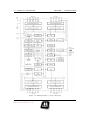
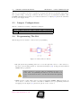
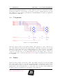
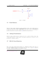
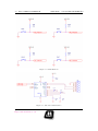
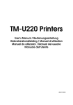
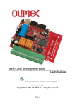
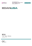
ATMega32 Kit - User Guide
K07B1V1
Contents
1 Introduction
4
1.1
Overview . . . . . . . . . . . . . . . . . . . . . . . . . . . . . . . . . . . . . . . .
4
1.2
Kit Features . . . . . . . . . . . . . . . . . . . . . . . . . . . . . . . . . . . . . . .
4
1.3
ATMega32 Processor . . . . . . . . . . . . . . . . . . . . . . . . . . . . . . . . . .
5
1.3.1
Memories . . . . . . . . . . . . . . . . . . . . . . . . . . . . . . . . . . . .
5
1.3.2
Clock Options . . . . . . . . . . . . . . . . . . . . . . . . . . . . . . . . .
6
1.3.3
I/O Ports . . . . . . . . . . . . . . . . . . . . . . . . . . . . . . . . . . . .
6
1.3.4
Peripheral Features . . . . . . . . . . . . . . . . . . . . . . . . . . . . . . .
6
1.3.5
Operating Voltage . . . . . . . . . . . . . . . . . . . . . . . . . . . . . . .
6
2 Using ATMega32 Kit
8
2.1
Overview . . . . . . . . . . . . . . . . . . . . . . . . . . . . . . . . . . . . . . . .
8
2.2
Power Supply . . . . . . . . . . . . . . . . . . . . . . . . . . . . . . . . . . . . . .
8
2.3
Jumper Configurations . . . . . . . . . . . . . . . . . . . . . . . . . . . . . . . . .
9
2.4
Programming The Kit . . . . . . . . . . . . . . . . . . . . . . . . . . . . . . . . .
9
1
CONTENTS
CONTENTS
3 On Board Peripherals
11
3.1
Overview . . . . . . . . . . . . . . . . . . . . . . . . . . . . . . . . . . . . . . . .
11
3.2
Display LEDS . . . . . . . . . . . . . . . . . . . . . . . . . . . . . . . . . . . . . .
11
3.3
7 Segments . . . . . . . . . . . . . . . . . . . . . . . . . . . . . . . . . . . . . . .
12
3.4
Buzzer . . . . . . . . . . . . . . . . . . . . . . . . . . . . . . . . . . . . . . . . . .
12
3.5
Push Buttons . . . . . . . . . . . . . . . . . . . . . . . . . . . . . . . . . . . . . .
13
3.6
Analog Potentiometer . . . . . . . . . . . . . . . . . . . . . . . . . . . . . . . . .
13
3.7
RS-232 Serial Interface . . . . . . . . . . . . . . . . . . . . . . . . . . . . . . . . .
13
4 Pin Allocation
15
4.1
Overview . . . . . . . . . . . . . . . . . . . . . . . . . . . . . . . . . . . . . . . .
15
4.2
I/O Pins assignment . . . . . . . . . . . . . . . . . . . . . . . . . . . . . . . . . .
15
5 Mechanical Dimensions
17
c
2010
M3ATronics
http://www.m3atronics.com
2
List of Figures
1.1
ATMega32 Kit . . . . . . . . . . . . . . . . . . . . . . . . . . . . . . . . . . . . .
5
1.2
ATMega32 Microcontroller Diagram . . . . . . . . . . . . . . . . . . . . . . . . .
7
2.1
Power Supply . . . . . . . . . . . . . . . . . . . . . . . . . . . . . . . . . . . . . .
8
2.2
ISP Connector Pinout . . . . . . . . . . . . . . . . . . . . . . . . . . . . . . . . .
9
2.3
JTAG Connector Pinout . . . . . . . . . . . . . . . . . . . . . . . . . . . . . . . .
10
3.1
LEDS . . . . . . . . . . . . . . . . . . . . . . . . . . . . . . . . . . . . . . . . . .
11
3.2
7 Segment Displays . . . . . . . . . . . . . . . . . . . . . . . . . . . . . . . . . . .
12
3.3
Buzzer . . . . . . . . . . . . . . . . . . . . . . . . . . . . . . . . . . . . . . . . . .
13
3.4
Push Buttons . . . . . . . . . . . . . . . . . . . . . . . . . . . . . . . . . . . . . .
14
3.5
RS-232 Serial Interface . . . . . . . . . . . . . . . . . . . . . . . . . . . . . . . . .
14
5.1
Mechanical Dimensions
18
. . . . . . . . . . . . . . . . . . . . . . . . . . . . . . . .
3
Chapter 1
Introduction
1.1
Overview
This document describes the ATMEGA32 Microcontroller kit. This board is designed to allow an
easy access to all the ATMEGA32 MCU peripherals and to be easily integrated in more advanced
projects. To increase its demonstrative capabilities, this stand alone board has numerous onboard
resources (RS232 Interface, 7-segments Display, General Purpose Press Switches, LED’s, Buzzer).
This user guide acts as a general getting started guide as well as a complete technical reference
for users.
1.2
Kit Features
Figure (1.1) shows the ATMega32 kit. The kit provides the following features:
• ATMEGA32 TQFP 44 device.
• Regulated 5V using External power connector.
• ICSP connector for on-chip In-Circuit Serial Programming (ICSP).
• Serial interface using RS-232 port. 4 Press Switches.
• 4 LEDs.
• 2 Seven-Segment Displays.
• Buzzer.
• Installed 8 MHz crystal.
4
1.3. ATMEGA32 PROCESSOR
CHAPTER 1. INTRODUCTION
Figure 1.1: ATMega32 Kit
1.3
ATMega32 Processor
The ATmega32 is a low-power CMOS 8-bit microcontroller based on the AVR enhanced RISC
architecture. By executing powerful instructions in a single clock cycle, the ATmega32 achieves
throughputs approaching 1 MIPS per MHz allowing the system designer to optimize power consumption versus processing speed. The kit is equipped with 44 lead TQFP ATMega32 processor.
Figure (1.2) shows a block diagram for the ATMega32 processor.
1.3.1
Memories
The AVR architecture has two main memory spaces, the Data Memory (SRAM) and the Program
Memory (Is-System Reprogrammable Flash Program Memory) space. In addition, the ATmega32
features an EEPROM Memory for data storage.
c
2010
M3ATronics
http://www.m3atronics.com
5
1.3. ATMEGA32 PROCESSOR
1.3.2
CHAPTER 1. INTRODUCTION
Clock Options
Allowable Operating speed for the ATMega32 ranges from: DC - 16 MHz clock input. The kit
is equipped with an 8 MHz crystal.
1.3.3
I/O Ports
32 programmable I/O lines divided into 4 ports, 8 pins each.
1.3.4
Peripheral Features
• 8-channel, 10-bit ADC.
• Two 8-bit Timer/Counters.
• One 16-bit Timer/Counter.
• Four PWM Channels.
• Programmable Serial USART.
• Master/Slave SPI Serial Interface.
• Programmable Watchdog Timer with On-chip Oscillator.
• On-chip Analog Comparator.
1.3.5
Operating Voltage
The ATMega32 processor operates from 4.5V to 5.5V.
c
2010
M3ATronics
http://www.m3atronics.com
6
1.3. ATMEGA32 PROCESSOR
CHAPTER 1. INTRODUCTION
Figure 1.2: ATMega32 Microcontroller Diagram
c
2010
M3ATronics
http://www.m3atronics.com
7
Chapter 2
Using ATMega32 Kit
2.1
Overview
This chapter is intended to act as a quick start for using the kit. It contains information needed
in order to start using the kit and experimenting with it. It is concerned with options or
configurations that the user can change in order to change the behavior of the board. It can be
used to run demonstration codes that can be downloaded from M3A website.
This product contains static sensetive devices. Observe proper
static handling precautions when touching the product.
2.2
Power Supply
Figure 2.1: Power Supply
8
2.3. JUMPER CONFIGURATIONS
CHAPTER 2. USING ATMEGA32 KIT
The on-board regulator provides a regulated 5V supply through an external DC input with a
safe operation range of 7.5V up to 12V DC. An On-board power on/off switch is available. The
POWER-ON LED is lit when the power switch is switched on. Figure (2.1) shows the schematic
for the power supply circuit.
2.3
Jumper Configurations
The kit contains the following configuration jumpers:
J8
Closed
Open
2.4
PA0 is connected to analog output of R26 potentiometer
PA0 can be used as a generic digital I/O
Programming The Kit
The kit supports two interface connectors for programming.
Figure 2.2: ISP Connector Pinout
• ISP (In System Programming) this can be done through J10 connector. J10 connects to
the microcontroller using SPI mode. J10 is shown in Figure (2.2). It supports any standard
ATMEL ISP programmer.
Caution should be exercised when programming the microcontroller fuses. Programming the fuses to use an external clock
source would render the microcontroller unreachable through SPI
mode.
• JTAG Connector (J9). This connector supports standard ATMEL JTAG debuggers. It
can be used to connect to the microcontroller for JTAG mode for programming as well as
debugging as well. Figure (2.3) shows the pinout of the connector.
c
2010
M3ATronics
http://www.m3atronics.com
9
2.4. PROGRAMMING THE KIT
CHAPTER 2. USING ATMEGA32 KIT
Figure 2.3: JTAG Connector Pinout
c
2010
M3ATronics
http://www.m3atronics.com
10
Chapter 3
On Board Peripherals
3.1
Overview
This chapter illustrates the onboard utility perihperals that are included in the kit to help in
developing applications and prototypes rapidly. Each utility is illustrated and discussed briefly.
3.2
Display LEDS
Figure 3.1: LEDS
11
3.3. 7 SEGMENTS
CHAPTER 3. ON BOARD PERIPHERALS
The kit includes 4 LEDs implemented on one line. They are connected to 4 successive port pins.
To light ON a LED, the corresponding port pin must be driven to LOGIC LOW level. To turn
OFF a LED, the corresponding port pin must drive a LOGIC HIGH level. Figure (3.1) illustrates
the schematics for LEDs part.
3.3
7 Segments
Figure 3.2: 7 Segment Displays
The kit is equipped with 2 seven segment displays. The displays are of the common anode
type. Each segment is enabled through a PNP transistor. Enabling a segment is done through
driving the corresponding enable pin to LOGIC LOW level. To enable a segment of the display,
the corresponding pin is to be driven to LOGIC LOW level as well. The two segments are
connected to the same data port for multiplexing purposes. An example usage for the seven
segment displays can be downloaded from M3A website. Figure (3.2) illustrates the schematics
for 7 Segments.
3.4
Buzzer
The kit is equipped with a piezo-electric buzzer. The buzzer generates a tone arround 1 KHz
when enabled. The buzzer is powered through a PNP transistor. Enabling the buzzer requires
the corresponding port pin to be driven to LOGIC LOW. The port pin is also selected to be a
PWM output so that the fundamental tone of the buzzer can be modulated using PWM signal
if required. Figure (3.3) illustrates the schematics for the buzzer part.
c
2010
M3ATronics
http://www.m3atronics.com
12
3.5. PUSH BUTTONS
CHAPTER 3. ON BOARD PERIPHERALS
Figure 3.3: Buzzer
3.5
Push Buttons
The kit is equipped with 4 push-buttons with a normally-open state. The 4 push buttons are
connected to 4 successive port pins. LOGIC HIGH level is observed on the corresponding port
pin when the button is not pressed. LOGIC LOW level is observed on the corresponding port
pin when the push button is pressed. Figure (3.4) illustrates the push buttons.
3.6
Analog Potentiometer
The kit is equipped with an analog potentiometer in order to generate an analog voltage. The
voltage ranges from 0V to 5V. The output of the analog potentiometer is connected to a port
pin through a configuration jumper.
3.7
RS-232 Serial Interface
The board is equipped with an RS-232 interface for communication with the target microcontroller using UART. The RS-232 uses the standard D-sub 9-pin connector. Figure (3.5) illustrates
the circuit containing the MAX232 level translation circuit.
c
2010
M3ATronics
http://www.m3atronics.com
13
3.7. RS-232 SERIAL INTERFACE
CHAPTER 3. ON BOARD PERIPHERALS
Figure 3.4: Push Buttons
Figure 3.5: RS-232 Serial Interface
c
2010
M3ATronics
http://www.m3atronics.com
14
Chapter 4
Pin Allocation
4.1
Overview
This section acts as a help for firmware developer. It describes the IO pins of the microcontroller
and their assignment on the on-board peripherals.
4.2
I/O Pins assignment
Pin
PA0
Functionality
Analog input from Potentiometer
PA1
PA2
PA3
PA4
PA5
PA6
PA7
Enable Seven Segment ’g’
Enable Seven Segment ’f’
Enable Seven Segment ’e’
Enable Seven Segment ’d’
Enable Seven Segment ’c’
Enable Seven Segment ’b’
Enable Seven Segment ’a’
15
Comments
J8 must be in “Closed” position, refer
to section [2.3]
Use logic low to enable segment
Use logic low to enable segment
Use logic low to enable segment
Use logic low to enable segment
Use logic low to enable segment
Use logic low to enable segment
Use logic low to enable segment
4.2. I/O PINS ASSIGNMENT
Pin
PB0
Functionality
Push button 1
PB1
Push button 2
PB2
Push button 3
PB3
Push button 4
PB4
PB5
PB6
PB7
Not
Not
Not
Not
assigned
assigned
assigned
assigned
Pin
PC0
PC1
PC2
Functionality
Not assigned
Not assigned
LED 4
PC3
LED 3
PC4
LED 2
PC5
LED 1
PC6
PC7
Enable Seven Segment S2
Enable Seven Segment S1
Pin
PD0
PD1
PD2
PD3
PD4
PD5
Functionality
Not assigned
UART TxD
UART RxD
Not assigned
Not assigned
Buzzer enable/disable
PD6
PD7
Not assigned
Enable Seven Segment Dot
CHAPTER 4. PIN ALLOCATION
Comments
Logic low detected when button is
pressed
Logic low detected when button is
pressed
Logic low detected when button is
pressed
Logic low detected when button is
pressed
Can be accessed from pin header
Can be accessed from pin header
Can be accessed from pin header
Can be accessed from pin header
Comments
Can be accessed from pin header
Can be accessed from pin header
Use logic low to enable LED / logic
high to disable LED
Use logic low to enable LED / logic
high to disable LED
Use logic low to enable LED / logic
high to disable LED
Use logic low to enable LED / logic
high to disable LED
Use logic low to enable segment
Use logic low to enable segment
Comments
Can be accessed from pin header
Can be accessed from pin header
Can be accessed from pin header
Use logic low to enable buzzer / logic
high to disable buzzer
Can be accessed from pin header
Use logic low to enable
Note that all controller can be accessed from pin header, even if the pins are assigned to some
resource in the board.
c
2010
M3ATronics
http://www.m3atronics.com
16
Chapter 5
Mechanical Dimensions
Figure (5.1) illustrates the mechanical dimensions for the ATMEGA32 kit.
17
CHAPTER 5. MECHANICAL DIMENSIONS
Figure 5.1: Mechanical Dimensions
c
2010
M3ATronics
http://www.m3atronics.com
18
c 2011 M3ATronics
Disclaimer:
R logo and combinations thereof, are registered trademarks of M3atronics.
All rights reserved. M3A,
Other terms and product names may be trademarks of others. The information in this document
is provided in connection with M3A products. No license, express or implied or otherwise, to any
intellectual property right is granted by this document or in connection with the sale of M3A products.
Neither the whole nor any part of the information contained in or the product described in this document
may be adapted or reproduced in any material from except with the prior written permission of the
copyright holder. The product described in this document is subject to continuous development and
improvements. All particulars of the product and its use contained in this document are given by
M3A in good faith. However all warranties implied or expressed including but not limited to implied
warranties of merchantability or fitness for purpose are excluded. This document is intended only to
assist the reader in the use of the product. M3A shall not be liable for any loss or damage arising from
the use of any information in this document or any error or omission in such information or any incorrect
use of the product.
19