1
Installation
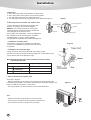
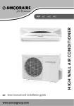
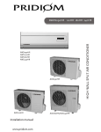
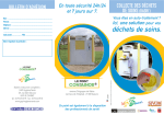
2. Outdoor units
* Leave enough margin around the unit to ensure
*
*
*
*
*
Figure 2
sufficient air circulation (Figure 2 shows the
recommended minimum dimensions)
Try to avoid exposure to direct sunlight.
Away from thermal sources of sources of combustible
gases.
Not to be installed in places where there is strong
wind and dust.
Not to be installed in places where the generated
noise and discharged air flow will cause troubles to
neighborhood.
Keep at least two sides open to outside.
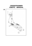
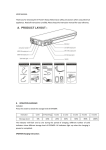
*.Installation of the indoor units
10 cm(3.94 inch)
and above
40 cm(15.8 inch)
and above
40 cm(15.8 inch)
and above
50 cm(19.7 inch)
and above
Figure 3
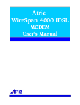
Pipe lines can be connected in the directions of**
******and* as indicated in Figure 3. When the
pipelines are connected to the directions of***and*,
a groove for the pipes has to be opened at the proper
place on the base stand.
*Left outlet
*Left rear outlet
*Right outlet
*Rear outlet
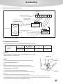
*.Installation of wall-mounting plate
Fix the wall-mounting plate firmly on the wall with
screws. Make sure of the leveling of the plate. Slanted
wall-mounting plate might jeopardize the smooth
discharge of the condensed water.
*Bottom outlet
Figure 4
Fix with a tape
5-10mm lower
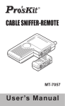
2. Drill holes on the wall
Drill holes at places slightly below the wall-mounting
plate, with hole diameter of 65mm and the outer
edge of the hole 5-10mm lower (Figure 4) so that
the condensed water can smoothly flow out. Cut the
wall penetrating pipe to proper length according to
the thickness of the wall (3-5mm longer than the
wall thickness) and insert the pipe as indicated in
Figure 4.
Wall cap
Wall pipe
Wall
Interior
Exterior
Figure 5
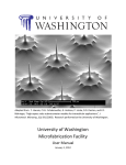
3. Installation of drain pipe
Install the pipelines of the indoor unit in accordance
with the direction of the wall holes. Wrap tightly the
drain pipe and the pipelines with tape. Make sure that
the drain pipe is underneath the pipelines. (Figure 5)
(When the drain pipe passes the room interior, some
condensed water might occur to its surfaces if the
humidity is very high).
Pipelines of indoor unit
Drain pipe
Rear pipe
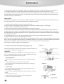
Figure 6
Top hooks
4. Installation of indoor unit
Pass the connection wires, connecting pipelines and
drain pipe through the wall hole. Hang the indoor unit
on the hooks at the top of the wall-mounting plate so
that the hooks at the bottom of the indoor unit match
the hooks of the wall-mounting plate. (Figure 6)
Hook supports
Bottom hooks
15
Installation
Inspections:
a. See if the hooks at the top and bottom are firmly fixed.
b. See if the position of the master unit is properly leveled.
c. The drain pipe should not curve upward (Figure 7).
d. The drain pipe should be at the lower part of the wall pipes (Figure 7).
Figure 7
5. Wire connections of indoor and outdoor units
Connect the wires of the indoor and outdoor units
properly according to the schematic diagram.
Note: Do not connect the wires in a wrong way,
otherwise electric malfunctions will be caused and
even damages to the units will occur.
If the supply cord is damaged , it must be replaced by
the manufacture or its service agent or a similarly
qualifited person in order to avoid a hazzard.
The plug shall be accessible after installed the appliance.
Connecting pipelines
Connecting wires
Wall pipe
Drain pipe
*.Installation of outdoor units
The outdoor unit should be installed on a rigid base
or stand. The installation surface should be as leveled
as possible.
Drain pipe
Figure 8
*.Installation the connection pipe
1.Align the center of the piping flare with then relevant valve.
2.Screw in the flare nut by hand and then tighter the nut with spanner and
torque wrench refer to the diagram at right.
Note:Exceeding tightening torque will damage the flare surface.
Tightening torqe table
Hex nut diameter
Tightening torque(N.m)
6mm(1/4")
15-20
9.5mm(3/8")
31-35
12mm(1/2")
50-55
*.Wire connections for outdoor units
As shown in Figure 9
* Remove the drawer of the outdoor unit, properly connect the wires to the
corresponding terminals in accordance with the electric schematic diagram and
make sure that the connection is firmly done.
* Use a press plate to fix the wires firmly, and re-install the drawer.
Note:
* Make sure that the wiring has been connect correctly.
* Wrong wiring connection will cause electrical mal-function.
* Do not pull the wire when fixing it with wire clamp.
16
Figure 9
Installation
Wrie and pipe connections for units
To power
L N A(L) A(N) A(S) B(L) B(N) B(S)
Outdoor unit terminal board
Connecting wire of
Connecting pipelines
indoor/outdoor unit
L NS
Indoor unit A
outdoor unit valve
A
L NS
B
Indoor unit B
indoor unit terminal board
NOTE:The height difference should be less than 15 meters between the indoor unit A and B,20 meters less between indoor
unit and outdoor unit after installing.
VI Refrigerant adjustment
If the liquid pipe length exceeds 10m,additional refrigerant charge is required.
liquid Pipe
length
10m maximum
No additional
charge require
exceeding 10m
Additional
charge require
_
Refrigerant to
be added
30g/m
example:
After the installation if the length of liquid connecting pipelines is 15 meters,the
refrigerant adjustment should be 150g.
Figure 10
NOTE:
The length of liquid connecting pipelines can not exceed 20 meters.
VI Air purging and leakage test
R22:
1. Remove the flare nuts from the cut-off valves of the outdoor unit.
2. Align the center of the piping flare with the relevant valve, and screw in
the flare nut about 3~ 4 turns hand.
3. Tighten the flare nut with spanner and torque wrench.
4. Remove the valve caps of the gas valve and liquid valve and the service
port nut.
5. Loosen the valve stem of the liquid valve with a hex wrench.
6. Push the check valve core of the gas valve to discharge air and moisture remaining in the refrigerant system.
7. Stop pushing the valve core as soon as the refrigerant starts to be discharged, and reinstall the service port nut.
8. Open the liquid valve and gas valve entirely(shown in Fig.10).
17
Installation
9. Tighten the valve caps and test leakage at all joints of the piping(both indoor and outdoor) with liquid soap or leak detector.
10. If possible, discharge air and moisture remaining in he refrigerant system with a vacuum pump.(shown in Fig.11)
11. CAUTION: If there is no exhaust or the exhaust capacity is not enough, please make sure all wires are connected correctly
first, then electrify the outdoor main power("L" "N") (no need to power on) for tens of seconds. When the corresponding electric
expansion valve opens, exhaust again.
R407C/R410a:
NOTE:During the installation or future maintenance,special material are for copper pipes,many-handed pressure gauge,valve,Fourway valve,compressor etc which touch refrigerant,These are different from R22.
1. Remove the flare nuts from the cut-off valves of the outdoor unit.
2. Align the center of the piping flare with the relevant valve, and screw in the flare nut about 3~ 4 turns hand.
3. Tighten the flare nut with spanner and torque wrench.
4. Remove the valve caps of the gas valve and liquid valve and the service port nut.
5.Connect the low-pressure needle value with the softly tube of refrigerant bottle.Open the bottle switch to let the air from the
small pipe flared nut for about 10 seconds.Tighted the flared nut after the with a torque force as indicated in Table 1.Then close
the bottle switch,loose the needle value junction and use a socket head cap wrench to with stand the needle to let remain refrigerant
out completely from the pipe.
6. Stop pushing the valve core as soon as the refrigerant starts to be discharged, and reinstall the service port nut.
7. Open the liquid valve and gas valve entirely(shown in Fig.11).
8.Prevented there is any leakage stop adding refrigerant and all refrigerant in system must be let out,then supply the lack,evacuation,
repour, and lay the refrigerant-container refering to the detailed description on it for pourig in liquid careful attention should be paid
during pouring. Furthermore all the R407c/R410a have to be let out if is poured too much,then pour again.
the way above is similarly available in future maintenance.
VII Outdoor condensation drainage(Heat pump type only)
When the unit is heating or defrosting, the waste water formed in the outdoor unit
can be drained out reliably through the drain hose.
Installation:
Install the outdoor drain elbow in the
25 hole on the base plate as shown in
Fig. 12, and joint the drain hose to the elbow, so that the waste water formed in
the outdoor unit can be drained out to a proper place.
*.Finishing touches
* Use thermal tube to wrap the joints and wrap the tube tightly with ethylene
tapes.
* Fix the wrapped pipelines on the exterior wall with clamps.
* Fill in the gaps left over by the pipeline hole and wall hole to prevent rainwater from entering.
*.Test running
* Connect to the power source, check if the function selection keys on the
remote controller are working properly.
* Check if the room temperature adjustments and timer settings are working
properly.
* Check if the drain is smooth.
* Check if there is any abnormal noise or vibration during operation.
* Check if there is leakage of refrigerant.
18
Figure 11
multiple gauge
high pressure side gauge
pressure
vacual mercury column
main regulation valve closed
pipelines
hand regulation valve closed
from high pressure side maintenance joint
to outdoor unit industrial pipe
R407C containor (brown)
refrigerant charging diagram
Figure 12
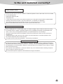
Is the unit installed correctly?
Suitable Installation Position
Isn't there anything which prevents ventilation or obstructs operation in front of the indoor unit ? Do not install
the unit following place .
Inflammable gases may leak .
Oil splashes a lot .
In case where the unit is used in such places as poisonous or sultry gases are generated or seaside district
exposed to sea breezes corrosion may cause malfunction . Consult with your distributor .
Air conditioner body and remote controller must be I m or more away from a TV or a radio .
Drain the dehumidified water from the indoor unit to a place which drains well .
Pay attention to operation noise
*When installing the unit , choose a place which can stand the weight of the unit well and does not increase
the operation noise or vibration . Especially where there is a possibility that vibration be transmitted to the
house , fix the unit by inserting attached vibration -proof pads between the unit and fittings .
*Choose the place where hot air and operation noise from the outlet of the outdoor unit do not annoy the
neighborhood .
*Things left near the outlet and inlet of the outdoor unit cause malfunction or increased operation noise .
Do not leave obstacles near the outlet and inlet .
*If irregular sound is heard during operation , consult with your distributor .
Inspection and Maintenance
According to the service conditions and operating environment , the inside of the air conditioner will become
dirty after several seasons (3 to 5years ) of service , resulting in decreased operating performance .Inspection
and maintenance are recommended in addition to usual cleaning (The air conditioner can be used for a longer
period and without anxiety .)
As to inspection and maintenance , consult your dealer or any one of business offices of dealing companies
.(Service charge is required in this case .)
We recommend to perform inspection and maintenance during an off seasons.
19