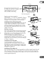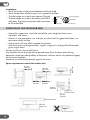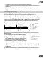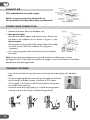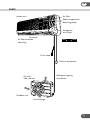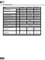
1
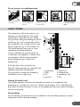
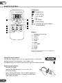
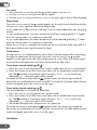
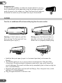
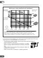
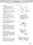
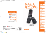
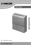
12EZ
18EZ
HIGH WALL AIR CONDITIONER
HW 9EZ
GB
User manual and installation guide
GB
THANK YOU
Thank you for choosing this innovative Amcor air conditioner. We suggest that you
keep this manual in a safe place for future reference. It describes the many benefits
and advanced features this unique product has to offer. Before you use your new air
conditioner you should carefully read these instructions to maximise this product’s
performance.
For over 50 years Amcor has specialised in complete indoor environmental control,
manufacturing and marketing; dehumidifiers, portable air conditioners, coolers, air
purifiers, ionisers and aroma therapy scent diffusers. These world class products
incorporate the latest technological developments.
SAFETY INSTRUCTIONS
IMPORTANT!
• The indoor unit is designed for indoor operation only.
• Rating: This unit must be connected to a 220 – 240 V / 50 Hz earthed outlet.
• The installation must be in accordance with regulations of the country where the
unit is used.
If you are in any doubt about the electrical installation, have it checked and if
necessary modified by a qualified electrician.
• The air conditioner is safe. However, as with other electrical appliances, use it
with care.
• Keep the remote control out of the reach of children.
• Do not clean the air conditioner by spraying it or immersing it in water.
• Do not insert any object into the opening of the air conditioner.
• Disconnect it from the mains before cleaning the unit or any of its components.
• Never connect the unit to an electrical outlet using an extension cord. If an outlet
is not available, one should be installed by a licensed electrician.
WARNING
• Never operate this appliance if it has a damaged cord or plug. Do not lead the
cord over sharp edges.
• A damaged supply cord should be replaced by the manufacturer, its service agent
or a qualified person in order to avoid a hazard.
• Any service other than regular cleaning or filter replacement should be performed
by an authorized service representative. Failure to do so could result in a loss of
warranty.
If you have any difficulties in connecting the refrigeration circuit please refer
to a professional air conditioning engineer.
2
GB
Do not use your air conditioner when:
the power cord is
damaged.
there is a chance
of liquids falling on
the unit.
there is a risk of
interference from
foreign objects.
it a close to a heat
source.
This air conditioner
is not made for DIY
repair.
HOW IT WORKS
The compressor (6) in the exterior unit
compresses the refrigerant into a hightemperature, high-pressure gas. When
this gas flows along the cooling fins of the
condenser (7), heat is extracted and the
gas condenses into a liquid, which is led
to the evaporator (1) in the interior unit.
The liquid expands into a gas at a low
temperature and low pressure.
This gas absorbs the warmth of the air
in the room, the cooled air is blown back
into the room and the heat absorbed
by the refrigerant gas is led to the
compressor.
A fan (3) draws the air (a) over the
filter (2) and evaporator (1) and blows the
cooled air (b) back into the room.
A fan (8) draws air over the condenser
and blows warm air (d) away.
1
a
2
3
4
c
b
6
7
5
d
8
1. evaporator
2. filter
3. fan
4. gas line
5. liquid line
6. compressor
7. condenser coil
8. fan
Heating (H-models only)
The system operates in reverse: the condenser works as an evaporator, the
evaporator as a condenser: warm air is blown into the room. This is ideal for cool
days when the main heating is not on, or to supplement the main central heating in
autumn and spring.
Dehumidifying
As with cooling, the moisture in the air condenses on the cold evaporator at room
temperature and is drained outdoors.
3
GB
REMOTE CONTROL
6
1
7
2
3
4
8
5
9
10
LCD display:
temperature
timer setting
timer on/off
fan
fan speed
louvre setting
or indication of active mode or
selected option
Buttons:
1. Temperature setting
2. ON/OFF
3. Swing
4. Air flow
5. Sleep
6. Mode
7. Fan speed
8. Timer
9. Turbo
10. Hold
NB Clean and Lamp buttons are not applicable
to this air conditioner.
Using the remote control
The remote control signal has a range of up to 8 m. Point the
remote control at the receiver in the indoor unit.
A beep confirms that the remote control signal has been received.
Replacing the batteries
• remove the cover
• replace the AAA batteries, + to + and – to -–
• install the cover
• press the on/off button; if no symbols appear on
the display, the batteries are empty or have been
incorrectly installed
4
GB
OPERATION
General
• Turn the unit on with the ON/OFF BUTTON [2]. The last used operating mode is
selected.
• The ON/OFF BUTTON turns the appliance off; the operating mode active at this
moment is stored in memory and will be used when the air conditioner is
switched back on again.
• Set the temperature with the TEMP BUTTONS [1] – within the limits of the
thermostat: 18 °C – 32 °C. Each press of the button makes a change of 1 °C.
• Use the FAN SPEED BUTTON [7] to set the fan speed at low , medium , high
or
automatic ( is flashing). The fan speed in the automatic setting is determined
by the difference between the set temperature and the room temperature.
• Use the SWING BUTTON [3] to adjust the horizontal (up/down) air flow direction.
Mode selection
Press the MODE BUTTON [6] to select the operating mode. The symbol on the left
side of the display indicates the selected mode.
Auto
1. Press the MODE BUTTON [6] until the symbol appears next to AUTO.
2. The temperature is automatically set to 25 °C and can not be adjusted.
3. Use the FAN SPEED BUTTON [7] to set the fan speed.
4. Use the SWING BUTTON [3] to adjust the air flow direction.
Cool
1. Press the MODE BUTTON [6] until the symbol appears next to COOL.
2. Set the desired temperature.
3. Use the FAN SPEED BUTTON [7] to set the fan speed.
4. Use the SWING BUTTON [3] to adjust the air flow direction.
Dry (dehumidify)
1. Press the MODE BUTTON [6] until the symbol appears next to DRY.
2. The temperature is automatically set to 25 °C and can not be adjusted.
3. The fan speed is automatically set to low and can not be changed.
4. The air flow direction is automatically set to fixed and can not be adjusted.
Heat
1. Press the MODE BUTTON [6] until the symbol appears next to HEAT.
2. Set the desired temperature.
3. Use the FAN SPEED BUTTON [7] to set the fan speed.
4. Use the SWING BUTTON [3] to adjust the air flow direction.
5
GB
Fan mode
1. Press the MODE BUTTON [6] until the symbol appears next to FAN.
2. Use the FAN SPEED BUTTON [7] to set the fan speed.
3. Use the SWING BUTTON [3] and the AIR FLOW BUTTON [4] to adjust the air flow direction.
Sleep button
Press the SLEEP BUTTON [5], the symbol appears on the right hand side of the display
next to SLEEP. Press again to release the sleep mode.
In this mode the air flow sound is reduced. Use the sleep mode when you are going
to bed.
In COOL mode operation, the room temperature will be raised gradually 2 °C higher
than the setting when SLEEP mode was activated.
In HEAT mode operation, the room temperature will be lowered gradually 5 °C lower
than the setting when SLEEP mode was activated.
When the SLEEP MODE is selected, the display on the unit will dim to be seen well in a
dark room without causing distraction to sleep.
Turbo button
During COOL or HEAT mode operation, the air flow rate (the amount of air circulating
through the room) can be increased. Press the TURBO BUTTON [9], the symbol
appears on the right hand side of the display next to TURBO. Press this button again
to cancel the turbo operation and return to the other air flow rates.
Timer button (timed switching off )
1. Press the TIMER BUTTON [8] to enter the “timed” mode when the unit is switched on.
2. Press this button to set after how many hours the air conditioner should switch
symbol in the display cycles through 1 2 ... 24 cancel (no
off. The
indication) 1... with each press of the button.
Once the set time has elapsed (the
symbol shows the remaining number of
hours) the air conditioner will switch itself off. To cancel this function before the set
time has elapsed, press the TIMER BUTTON [8] again.
Timer button (timed switching on)
The air conditioner is switched off (stand-by).
1. Press the TIMER BUTTON [8] to enter the “timed” mode.
2. Press this button to set after how many hours the air conditioner should switch
on. The
symbol in the display cycles through 1 2 ... 24 cancel (no
indication) 1... with each press of the button.
3. Set the desired operation, temperature, fan speed, etc.
Once the set time has elapsed (the
symbol shows the remaining number of
hours) the air conditioner will switch itself on. To cancel this function before the set
time has elapsed, press the TIMER BUTTON [8] again.
Hold button
6
GB
Press the HOLD BUTTON [10] to lock or to unlock the keys of the remote control. The
symbol on the right hand side of the display next to HOLD indicates locked keys.
Left/right air flow direction
Method 1: Manually adjust
Turn the air conditioner off. Adjust the fins by hand.
Method 2: Horizontal and vertical auto swing
Press the AIR FLOW BUTTON [4] to let the fins swing constantly or leave them in a fixed
manual set postion.
IMPORTANT
Auto restart
The air conditioner will automatic restart when electricity is restored after a power
cut. If in doubt, check the settings.
Range of internal thermostat
The internal thermostat can be set at a desired temperature between 16 and 32 °C.
Note that whether the desired value is achieved depends on conditions in the room.
Range of heat pump function
The heat function can be used to supply low cost heat when the external
temperature is approximately 10 °C or higher.
Note that it may not operate properly at lower external temperatures, it will cycle
frequently to defrost the outdoor coil and stops operating at minus 5 °C.
Capacity
The required cooling or heating capacity depends greatly on the location and/or use
of the room where the air conditioner is installed. Strong sunlight and the presence
of people, lights or equipment create an additional heat load with resulting smaller
reduction in room temperature.
Normal living spaces require about 100 W per square metre of floor surface. In
strong sunlight or if other sources of heat are present, this may be as much as
350 W/m2.
Tip: on warm days, let the air conditioner cool the room as much as possible during
the night. Cold walls and furniture will help to keep the room pleasant during use.
Avoid strong sunlight.
Aim for a room temperature only up to 3–5 °C lower than ambient temperature to
save energy and shock to the body when moving out of the conditioned space. The
air conditioner will dry the air, making it more comfortable even if not very cold.
7
GB
Emergency start
In the event of a problem, or when the remote control is missing,
the air conditioner can be operated using the emergency button
under the panel in the indoor unit. Open the front panel and press
the button to switch on (in the mode last set) or to switch off.
FILTERS
Turn the air conditioner off and remove the plug from the mains outlet.
A
A
Opening: at the A recesses, pull the
front part up. The front part will stay
horizontal (turn up 90 °).
B
C
B
Closing: press the front part down at
the sides at B and in the middle at C.
Make sure it is properly closed (click).
1. Hold the front part open (or put it in horizontal position) and remove the
filter(s).
2. Tap the filter gently or use a vacuum cleaner to remove dirt. If the dust filter
is very dirty, it may be washed in lukewarm water with a very small amount of
neutral detergent. Rinse well and allow to dry completely (not in direct sunlight or
near a source of heat).
3. Keep the grid panel open and reinstall the filter(s). Press the panel shut; a click
indicates it is closed properly.
4. Plug the appliance back in and turn it on.
8
GB
CLEANING
Turn the air conditioner off and remove the plug from the mains outlet.
Indoor unit
Dust regularly with a dry cloth or slightly damp paper towel.
Never use chemicals or solvents. Never spray a liquid in or over the appliance.
Outdoor unit
Remove dirt and keep the air intake and exhaust openings free of leaves, etc.
Cleaning with chemicals may cause damage.
END OF PERIOD OF USE
If the air conditioner is not going to be used for an extended period:
• set in fan mode with temperature set at 30 °C (86 °F) so that the inside of the
appliance dries out.
• remove the plug from the outlet (even when switched off the air conditioner will
consume about 5 W) and take the batteries out the remote control.
• clean the indoor and outdoor unit.
• clean the filters as well.
START OF PERIOD OF USE
If the air conditioner is to be used again after an extended period:
• check that the air intake and exhaust openings of the indoor and outdoor unit are
not blocked. Remove all dirt and obstacles.
• check that there is a filter.
• check that the condensation outlet drains properly.
• install 2 AAA batteries in the remote control.
• dust the indoor unit.
• turn the appliance on, set the time and desired setting.
Note: make sure condensation is drained freely and that there is no obstacle such
as algae growth, otherwise leaks may occur.
9
GB
INSTALLATION GUIDE
8IJDISPPNJTCFTUTVJUFEGPSUIF"JS$POEJUJPOFS
.BOZXJOEPXT
.VDITVOTIJOF
4PVUIGBDJOH
4J[FPGUIFSPPN
GMPPSBSFB
8 N
N
N
-FTTXJOEPXT
-FTTTVOTIJOF
/PSUIGBDJOH
N
8
N N
$PPMJOHDBQBDJUZ
8
8
8
8
8
"TVJUBCMFSPPNEFQFOETPOUIFDPPMJOHDBQBDJUZTVOMPDBUJPOXJOEPXBSFBQSFTFODFPG
IFBUTPVSDFTMBNQTBQQMJBODFTOVNCFSPGQFPQMFFUD
5BLFUIJTJOUPBDDPVOU
3VMFPGUIVNCJOBWFSBHFTVOTIJOFDPOEJUJPOTBOEOPQSFTFODFPGPUIFSIFBUTPVSDFT
8QFSTRVBSFNFUSFUIVTBDPPMJOHDBQBDJUZPG8JTCFTUQMBDFEJOBNSPPN
In case of a non quick coupling unit, make sure to have the professional after-sales
service person or authorized dealer to install the units.
• The units may not be installed in places where there might be leakage of
combustible gases: fire hazard.
• Make sure that an earth leakage circuit breaker is installed,
either as a plug in device or on the main board, instead of a
fuse.
• Check whether the connection of wires between indoor and
outdoor unit is not loose.
• Make sure that the air conditioner is properly grounded.
10
GB
SAFETY ASPECTS
Check the network voltage.
Make sure that the existing network voltage corresponds to the value specified on
the type tag on the appliance.
Keep the work area tidy.
Carelessness in the work area can lead to accidents.
Use the right tools.
Do not use tools that are not sturdy enough for heavy work. Use reliable tools
suitable for the purpose for which they are intended.
Wear a mask and eye and ear protection.
When doing work which may produce splinters or dust and when working over your
head always wear eye protection and a well-fitting face mask. Wear ear mufflers in
noisy conditions.
Extension cord when working outdoors.
Only use approved and correspondingly marked extension leads and sockets during
work out of doors.
Check electrical equipment for any damage.
Never use equipment with a switch that does not work.
Be careful when working on steps, ladders and scaffolding.
Be extra careful when working on an elevated surface. Make sure that stepladders,
steps, ladders and scaffolding are placed correctly and cannot slip.
Electrical cables, gas and water pipes etc.
Important safety aspect for work with drilling equipment:
Make sure that when drilling you cannot strike electrical cable, gas or water pipes.
Check the wall with a duct/cable detector before you start drilling.
Is everything clear?
Once you have familiarised yourself with the safety recommendations and have
learnt from the user’s manual how to use the tools, you can start working. By
following the instructions and recommendations of the manufacturers you can be
sure that you are working as safely as possible.
Keep these guidelines!
11
GB
SAFETY
Read the section on safety aspects and these instructions before you start.
Stick to the work sequence and working method shown here.
For technical or commercial reasons, the manufacturer may make changes to the
appliance or component parts, without general notification. You can consult your
supplier about this.
IMPORTANT:
• This appliance must be connected to an earthed socket for 230 V/50 Hz, with a
13 A fuse.
• The connection to the national grid must be carried out in agreement with the
safety standards as regards the installation of electrical household appliances
applicable in the country of use.
If in doubt have the electrical installation checked and if necessary modified by a
qualified electrician
Ensure you have:
• a well lit and a work area clear of clutter.
• a well thought out and pre-arranged work plan.
• sound tools and reliable implements.
• protection: safety goggles, ear protection, mask, hard hat, work shoes and work
gloves.
The outdoor unit must be lifted and put in place by two people.
POSITION OF THE INDOOR UNIT
Install the indoor unit where there is:
• no influence from outdoor air,
• no blockage of air inlet or air outlet,
• no smoke or steam, and no generation, inflow, lingering or leakage of flammable
gases,
• no high-frequency facility (such as arc welder).
Avoid places where acid solutions or some special sprayers (sulfides) are frequently
used.
• The air from the indoor unit should reach every corner of the room.
• Do not install a fire alarming device near the air outlet, the alarm may
erroneously be triggered by the warm air from the unit.
12
GB
Ceiling
At least 10 cm
For operational convenience and At least
for safety, ensure there is enough 15 cm
space between the unit and
walls, windows and ceiling.
At least
15 cm
At least 230 cm
Wall-mounting plate
Floor
Pipe lines can be connected in
the directions 1, 2, 3, 4 or 5 as indicated in Figure 3.
When connection 3, 4 or 5 is chosen, a groove for
the pipes has to be opened on the base stand.
Installation of the wall-mounting plate
Fix the wall-mounting plate firmly on the wall with
screws. Make sure the plate is level. A slanted
wall-mounting plate may jeopardize the smooth
discharge of the condensed water and cause the
indoor unit to leak.
Drill hole in the wall
Drill a hole slightly below the wall-mounting plate,
with a diameter of 65 mm and the outdoor edge
of the hole 5–10 mm lower (Figure 4) so that the
condensed water can smoothly flow out.
Cut the wall penetrating pipe to proper length
according to the thickness of the wall (i.e. 3–5 mm
longer than the wall thickness) and insert the pipe
as shown in Figure 4.
Installation of the drain pipe
Install the pipelines of the indoor unit in
accordance with the direction of the wall holes.
Wrap the drain pipe and the pipelines tightly with
tape. Make sure that the drain pipe is underneath
the pipelines (Figure 5).
Installation of the indoor unit
Pass the connection wires, connecting pipelines and drain pipe through the wall
hole. Hang the indoor unit on the hooks at the top of the wall-mounting plate
so that the hooks at the bottom of the indoor unit match the hooks of the wallmounting plate (Figure 6).
13
GB
Inspections:
• See if the hooks at the top and bottom are firmly fixed.
• See if the position of the master unit is properly levelled.
Connecting
• The drain pipe must not curve upward (Figure).
wires
• The drain pipe must be at the lower part of the
wall pipes (Figure) to avoid possible restriction
Drain pipe
to the water flow.
Connecting pipe
Wall pipe
Drain pipe
POSITION OF THE OUTDOOR UNIT
• where the support can stand the load of the units weight and not cause
vibrations and noises
• where it is not exposed to rain or direct sunshine, but has good ventilation, no
restriction to the air flow
• where noises will not affect neighbouring places
• away from areas where generation, ingress, stagnant or leakage of inflammable
gases might occur.
Do not install on a non-metal frame.
Pay attention to the drainage of condensed water from the base plate during
operation. Avoid possible puddles or flow over surfaces which may become slippery
and a hazard to others.
Avoid the air outlet being directly against the wind.
At least
1000 mm
At least
200 mm
At least
200 mm
At least
200 mm
At least 500 mm
At least 500 mm
Space requirements around the outdoor unit
At least
300 mm
At least
200 mm
Space for
maintenance
At least
500 mm
At least 200 mm
At least
1000 mm
14
GB
• use expansion bolts to fix the mounting supports on the wall
• use bolts and nuts to fix the outdoor unit firmly on the supports and keep on the
same level
• if the unit is installed on the wall or at the roof top, the supports have to be firmly
fixed to resist earthquake or strong wind.
PIPELINES CONNECTION
Ordinary pipeline connection (suitable for non-quick coupler)
No dust, foreign objects, air or moisture should be allowed to enter the air
conditioning system. Careful attention should be paid when the pipeline connection
for the outdoor unit is made. Avoid (repeated) curves as much as possible,
otherwise hardening or cracks might be caused to the pipes. Suitable wrenches
should be used when the pipeline connection is done to ensure appropriate torque.
Excessive torque might damage the joints while too little torque might lead to
leakage.
For pipes vacuuming, see “Exhaust air” paragraph.
Torque wrench
Diameter of the copper pipe
[“] / [mm]
1/4” / 6.35 mm
3/8” / 9.52 mm
Tightening torque
[kgf*m]
[Lbs/feet]
1.6
11.6
3.0
21.7
Spanner
Nut of
connecting pipe
Joint
Connect the indoor connections (suitable for quick coupler)
Be aware that it is possible to connect the connectors only in one way. Follow the
procedure below:
a. Remove the 4 dust caps from indoor connectors
Quick coupler
(unit and pipes).
(wrapping with insulating c
Low pressure valve
b. Align the joint counter to the connecting pipe
with the proper joint, tighten the connecting nuts
Valve core cap
High pressure valve
manually. Then, make it secure with a wrench
applying torque as shown in the table. If a torque
meter is not available, secure the connector with
1 turn after manual secure.
c. Connect the drain hose to the indoor drain outlet. Wrap the drain tube with the
refrigerant tubes tightly with tape. Make sure that the drain pipe is underneath
the pipelines.
d. Connect the electric plugs, and place it above tubing in the back side of the unit.
15
GB
multiple gauge
EXHAUST AIR
Only applicable for non-quick coupler.
pressure
high pressure
side gauge
vacual mercury column
main regulation
valve closed
R410A: use pump vacuum to exhaust the air.
This procedure must be performed by a professional.
to outdoor unit
industrial pipe
hand regulation
valve closed
from high pressure side
maintenance point
R407C/R410A
container (brown)
refrigerant charging diagram
POWER CABLE CONNECTION
1. Remove the cover from the outdoor unit.
2. Non-quick coupler:
connect the indoor power and control wires firmly with
the ones in the outdoor unit as shown in Figure 11 - top.
Quick coupler:
directly connect the quick cable coupler from the indoor
unit with the one from the outdoor unit (Figure 11
– bottom).
3. Use a pressing plate to fix the wires firmly and replace
the cover.
Figure 11
wire pressing
plate
Drawer Screw
Note: Incorrectly connected wires may lead to electric malfunction and can
damage the units. See safety instructions on pages 2 and 12 for electric installation
compliance and damaged cable.
FINISHING TOUCHES
• Use a thermal tube to wrap the joints and wrap the tube tightly with ethylene
tape.
• Fix the wrapped pipelines vertically on the external wall with
duct through and pipe clamps, available at DIY-stores.
Fill the gaps in the holes made for the pipeline to prevent
rain-water from entering.
• Lead the water drainage pipe to a suitable drainage point,
making sure that the water can flow through freely.
16
GB
PARTS
Indoor unit
Air filter
Room temperature
detecting probe
Emergency
start/stop
Air outlet
Air flow direction
adjusting
RUN
•
• TIMER
Drain tube
Electric connection
Air inlet
side and rear
Refrigerant piping
connection
Outdoor unit
Air discharge
17
GB
TECHNICAL DATA
Model
Cooling capacity
measured conform EN 14511
Heating capacity
Power supply
Power consumption
Current
Dehumidification – max.
Air flow – at high fan speed
Refrigerant
Refrigerant load
Room size – up to
Fan speeds
Thermostat
Timer
Dimensions (W x D x H)
– indoor unit
– outdoor unit
Weight
– indoor unit
– outdoor unit
BTU/h
kW
BTU/h
kW
W
A
L/24h
m3/h
g
m2
°C
h
mm
kg
HW-9EZ
9200
2.7
9500
2.8
HW-12EZ
HW-18EZ
12000
16500
3.51
4.82
12300
17400
3.6
5.1
220 – 240 V • 50 Hz • 1Ph
840/780
1100/1000
1600/1580
3.9/3.7
5.06/4.7
7.27/7.4
17
24
31
500
600
729
R410A
760
1080
1500
27
35
47
3
16 – 32
1 – 12
790 x 180 x 270 790 x 180 x 270 940 x 180 x 270
700 x 225 x 500 795 x 255 x 540 850 x 295 x 605
9
27
10.5
36
Subject to modifications without prior notice. Please refer to the rating label for greater precision.
18
14
45
GB
ELECTRIC CONNECTION (UK ONLY)
For your safety please read the following information.
Warning: This appliance must be earthed.
The appliance must be connected to a 220-240 volts 50 cycle AC supply by means of a three pin socket,
suitably earthed and should be protected by a 13 amp fuse in the plug.
The appliance is supplied with a moulded 13 amp 3 pin mains plug fitted with a 13 amp fuse. Should the
fuse require replacement, it must be replaced with a fuse rated at 13 amp and approved to BS1362.
The plug contains a removable fuse cover that must be refitted when the fuse is replaced. In the event
of the fuse cover being lost or damaged, the plug must not be used until a replacement cover has been
obtained.
If the moulded mains plug is unsuitable for the socket outlet in your home or is removed for any other
reason, then the fuse should be removed and the cut off plug disposed of safely to prevent the hazard of
electric shock.
There is a danger of electric shock if the cut off plug is inserted into any 13 amp socket outlet.
How to wire a 13 amp plug.
Important
The wires in the mains lead on this appliance are coloured in
accordance with the following code:
Green and Yellow
– Earth
Blue
– Neutral
Brown
– Live
The green and yellow wire must be connected to the terminal
in the plug which is marked with the letter E or with the earth
symbol
.
The blue wire must be connected to the terminal marked N
The brown wire must be connected to the terminal marked L.
19
Hong Kong
Amcor Ltd
Suite 1010–1011, 10/F, Ocean Centre,
Harbour City, 5 Canton Road,
Tsim Sha Tsui, Kowloon,
Hong Kong
Tel: +852 2997 6865
Fax: +852 2997 6091
Email: [email protected]
United Kingdom
Amcor Ltd
9 Ryan Drive, West Cross Centre,
Great West Road, Brentford,
Middlesex, TW8 9ER,
United Kingdom
Tel: +44 20 8560 4141
Fax: +44 20 8232 8814
Email: [email protected]
USA
Amcor Inc.
685A Gotham Parkway, Carlstadt,
New Jersey 07072,
United States of America
Tel: +1 201 460 8100
Fax: +1 201 460 9481
Email: [email protected]
The Netherlands
Amcor B.V.
Anton Philipsweg 9-11,
1422 AL Uithoorn,
The Netherlands
Tel: +31 297 560 079
Fax: +31 297 523 062
Email: [email protected]
Plant One - Amcor (China) Ltd
Tel: +86 769 8372 1090
Fax: +86 769 8372 1790
Email: [email protected]
Plant Two - Amcor Appliances Ltd
Tel: +86 769 8372 1970
Fax: +86 769 8372 1790
Email: [email protected]
913126320
Singapore
Amcor Investments (Singapore) Pte Ltd
545 Orchard Road,
#13-02, Far East Shopping Centre,
Singapore 238882
Tel: +65 6297 9881
Fax: +65 6297 8891
Email: [email protected]
China
Shan Xia Industrial Development Zone,
Heng Li Town, Dongguan City,
Guangdong Province, China
HW-EZ
Israel
Amcor International Ltd
1 Sapir St.,
P.O. Box 12001,
Hertzelia Pituach,
Israel
Tel: +972 9 951 5351
Fax: +972 9 958 5650
Email: [email protected]