1
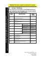
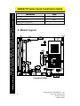
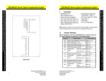
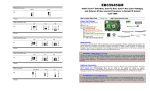
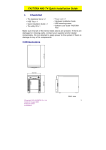
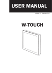
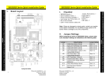
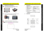
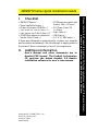
SBC84710 Series Quick Installation Guide
Checklist
9 SBC84710 Board x 1
9 Quick Installation Guide x 1
9 Product Information CD-ROM x 1
9 2-pin jumper cap, Pitch=2.54mm x 10
9 2-pin jumper cap, Pitch=2.0mm x 10
9 COM+Printer extension cables with
bracket, Pitch=2.0mm x 1
9 2COM extension cables with
bracket, Pitch=1.27mm x 1
9 ATX Power Cable 10P
L=150mm
9 Audio Cable x 1
9 USB Cable x 1
9 2.5” & 3.5” HDD cable x 1
If there are damaged or missing parts, contact your supplier
and/or dealer immediately. Do not attempt to apply power to
the board if there is damage to any of its components.
II.
Additional Information
User’s Manual and other documents are in
Acrobat PDF format. The Product Information
CD contains the Adobe Acrobat 3.0 Reader
installation software for user’s convenience.
©Copyright 2007 AXIOMTEK Co., Ltd.
Version A1 February 2007
Printed in Taiwan
94284710000E
1
Please refer to the Product Information CD for the complete version of the User’s Manual,
drivers, and utilities for the SBC84710 Series CPU Card.
I.
SBC84710 Series Quick Installation Guide
Please refer to the Product Information CD for the complete version of the User’s Manual,
drivers, and utilities for the SBC84710 Series CPU Card.
III. Jumper Settings
Before turning on the power to the SBC84710 Series,
please make sure that all jumpers are on their default
settings as listed on the table below.
Jumper
JP3
Default Setting
Normal Operation/Clear CMOS setting
Jumper
Setting
Short 1-2
Default: Normal Operation
JP4
Compact Flash Voltage Selection
Default: 5V
Short 1-2
JP6
LVDS Voltage Selection
Short 1-2
Default: 3.3V
JP7
JP8
JP9
JP10
CN16
COM4 Mode Select
COM3 Mode Select
COM2 Mode Select
COM1 Mode Select
COM4 Pin 1: DCD
Short 7-9
COM4 Pin 9: RI
Short 8-10
COM3 Pin 1: DCD
Short 7-9
COM3 Pin 8: RI
Short 8-10
COM2 Pin 1: DCD
Short 7-9
COM2 Pin 8: RI
Short 8-10
COM1 Pin 1: DCD
Short 7-9
COM1 Pin 8: RI
Short 8-10
COM1 Mode Select
Short 1-2
Default: RS-232
CN24
COM1 Mode Select
Short 3-5,4-6
Default: RS-232
CN26
COM1 Mode Select
Short 3-5,4-6
Default: RS-232
CN25
Audio Speak Out/Line Out Selection
Short 1-3,2-4
Default: Line Out
2
©Copyright 2007 AXIOMTEK Co., Ltd.
Version A1 February 2007
Printed in Taiwan
94284710000E
SBC84710 Series Quick Installation Guide
SBC84710 Connectors
Connectors
Label
HDD Activity LED Connector
CN1
System Reset Switch Connector
CN2
SATA Connector
CN3
Primary IDE Connector
CN4
Power Connector
CN5
+12V Only
CN6
2*10pin DIO
CN7
Mini PCI Slot
CN8
PC104-A
CN9
LVDS Backlight Connector
CN10
PC104-B
CN11
Printer Port Connector (LPT)
CN12
LVDS Connector
CN13
Audio Connector
CN14
COM2,COM4 Connector
CN15
COM3 Connector
CN17
Front Panel Connector (Buzzer)
CN18
Front
LED)
Please refer to the Product Information CD for the complete version of the User’s Manual,
drivers, and utilities for the SBC84710 Series CPU Card.
IV
Panel
Connector
(Power
CN19
Power Button
CN20
CPU Fan Connector
CN21
USB2,USB3 Connector
CN23
USB0,USB1 Connector
CN27
COM1Connector
CN28
PS/2 Connector
CN29
VGA Connector
CN30
F.D.D Connector
CNS1
©Copyright 2007 AXIOMTEK Co., Ltd.
Version A1 February 2007
Printed in Taiwan
94284710000E
3
SBC84710 Series Quick Installation Guide
Please refer to the Product Information CD for the complete version of the User’s Manual,
drivers, and utilities for the SBC84710 Series CPU Card.
Connectors
Label
DDR RAM Connector
CNS2
CF Connector
CNS3
Ethernet Connector
LAN1
V Board Layout
Component Side
4
©Copyright 2007 AXIOMTEK Co., Ltd.
Version A1 February 2007
Printed in Taiwan
94284710000E