1
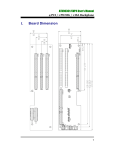
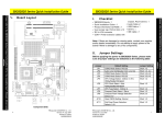
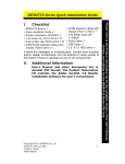
eBOX530-820-FL Quick Installation Guide
Turn off the system, and unplug the power cord.
Turn the system upside down to locate screws at the bottom,
loosen screws to remove the back cover.
I.
Packing List
9 eBOX530-820-FL System
Unit x 1
9 eBOX530-820-FL Quick
Installation Guide x 1
9 Power Cord x 1
9 Y Cable for PS/2 Keyboard &
Mouse x 1
9 CD x 1 (for Driver and SBC
User’s Manual)
9 25W 5V AC/DC Power Adapter
x1
9 Wallmount Bracket x 2
9 NOTICE x1
9 M3x4 Screws x 4
9 HDD Mylar x1
¾ Do not try to apply power to the system if any damaged
components.
Step 3
Step 4
Assembly the HDD bracket, together with the HDD Mylar, and fix it
all into the system, and plug the power cable in HDD.
II.
Dimensions
Close the cover to the chassis, and fasten all screws.
MAXIMUM DEPTH OF THE HDD BRACKET : 2.5mm (when installing DIN
Mount)
4
©Copyright 2009 AXIOMTEK Co., Ltd.
Version A2 April 2009
Printed in Taiwan
94260530020E
©Copyright 2009 AXIOMTEK Co., Ltd.
Version A2 April 2009
Printed in Taiwan
94260530020E
1
There is a User’s Manual CD-ROM for the CPU card installed in your eBOX530-820-FL system. Please consult your
local vendor for assistance if you have any difficulties in installing. the system.
Installing the Hard Disk Drive
Step 1
Step 2
.
X
A
M
m
m
5
.
2
H
T
P
E
D
contact authorized technicians for a professional handling.
All Components are fragile and sensitive. If you need to replace or return any components for repair, you must
V.
eBOX530-820-FL Quick Installation Guide
eBOX530-820-FL Quick Installation Guide
I/O Outlets
IV.
The following figures show you I/O outlets on front and rear panels
of the eBOX530-820-FL Series.
¾
Turn off the system, and unplug the power cord.
Turn the system upside down to locate screws at the bottom,
loosen screws to remove the back cover.
Step 3
Locate the memory module, insert the gold colored contact into the
socket. Push the module down, until it is firmly seated by locking
two latches on the sides.
Step 4
Close the cover to the chassis, and fasten all screws.
AUDIO
CONNECTORS
COM1/2
CONNECTORS
¾
Step 1
Step 2
Front View
4 x USB 2.0
CONNECTORS
Installing the Memory Module
PS/2
CONNECTORS
FOR KB/MS
Rear View
5V DC-IN
VGA
POWER INPUT CONNECTOR
CONNECTOR
RJ-45
POWER-ON
CONNECTOR
SWITCH
FOR ETHERNET
2
©Copyright 2009 AXIOMTEK Co., Ltd.
Version A2 April 2009
Printed in Taiwan
94260530020E
©Copyright 2009 AXIOMTEK Co., Ltd.
Version A2 April 2009
Printed in Taiwan
94260530020E
3
There is a User’s Manual CD-ROM for the CPU card installed in your eBOX530-820-FL system. Please consult your
local vendor for assistance if you have any difficulties in installing. the system.
contact authorized technicians for a professional handling.
All Components are fragile and sensitive. If you need to replace or return any components for repair, you must
III.
eBOX530-820-FL Quick Installation Guide