Download YGE ProgCard II - Programming Card
Transcript
YGE ProgCard II - Programming Card
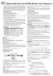
With the programming card we offer you an easy to use
programming unit which allows you to change every single
function of our ProgCard II compatible ESC’s. A special feature
is the exact cutoff voltage adjustment for the two Lithium
batteries types on the market with their respective number of
cells. Further can be adjusted the timing, different brake
modes, the governor speed regulation and the accurate
throttle stick positions by means of buttons. The current
settings can be read back with all our ESC’s with BEC.
ESC’s with integrated opto-coupler cannot be read back by the
progCard II.
By activating the LiFe cell type (LiFePO4), the cutoff
voltage is reduced by 0.7V per cell.
Cutoff voltage (upper cutoff voltage line) for LiFe is 2.2 to
2.7V per cell.
Cutoff voltage (lower cutoff voltage line) for LiPo is 2.9 to
3.4V per cell.
In the NiMh mode, neither the cutoff voltage nor the cell
count needs to be programmed. The slowdown is done
automatically based on the battery voltage during
connection. (Therefore, use only fully charged NiMh
batteries)
In addition to the LED matrix overview, the confirmation of the
respective programming step is done via an acoustic signal,
which is produced by the motor connected to the ESC.
All this is possible without the otherwise usual stick
programming.
For the throttle stick range calibration, please connect the
enclosed extension cable from the receiver to the rightmost
connector of the ProgCard II.
Operating instructions
Turn on the transmitter, and put the throttle on stop. Select
the stop LED on the ProgCard II and push the Enter
button. Do the same with the full power position and the
Full Speed LED.
Disconnect the flight battery from the controller.
Unplug the command cable from the receiver (or opto-coupler)
and plug it into the left connector of the ProgCard II. The left
contact is signal (white, yellow or orange), the center contact is
+5V (red), and the right contact is minus (brown or black).
If you inadvertently the plug the connector the wrong way,
nothing happens, since the ProgCard II is protected against
reversals.
Acro special (F3A Brake)
This function allows to adjust the F3A brake intensity
without any step. You need again the extension cable, like
described above, select the Acro Special LED, position
the stick, e.g. for 50% brake on half throttle, and press the
enter key. Likewise for 75%, put the stick on ¾ gas, etc.
Connect now the flight pack to the ESC. On the progCard the
upper LED of the lateral LED column will light. The ESC-Motor
unit will signal 6 Beep (short melody)
Shortly after that the current settings are read form the ESC as
long as it is a BEC model. All LED will light up in a row. You
are now on level 1, starting with the timing indicator. Now you
choose with the lower left button the Menu selection and can
see the programmed setting on the LED line. With the upper
left button you can now choose a new value that will be
actually programmed into the ESC with the Enter button on the
right. The ESC will acknowledge with a positive beep. (The
LED on the ProgCard II will turn off shortly and is followed by a
low and a high tone beep.)
Functions that cannot be programmed in the ESC are signaled
with a negative beep. (1 low tone)
All function can be adjusted like that, while the programming
order is not relevant except for the Lipo type followed by the
cutoff voltage adjustment and the cell count.
Though, you can modify later on any single value anytime.
2 and 3 cells are recognized automatically by the controller.
That is why the cell count settings are starting with 4 cells on
the ProgCard II.
The programming of the cell count is saved in the controller.
Connecting a different cell count battery would lead to wrong
under voltage detections.
Setting again the Lipo type (LiPo / LiFe) will cancel the cell
count and set the ESC again in automatic cell count detection!
To program the ESCs with integrated opto-coupler you
always need the extension cable like described above, as it
is powering the ProgCard II through the receiver.
To program an ESC with an additional external optocoupler, you have to remove the opto-coupler first.
To calibrate the throttle range, the stop and full power
position needs to be reduced by 10% in the transmitter
because the opto-coupler has a propagation delay of 50µs
and thus the stop and full power points are shifted.
Level 2.
All other functions like the governor mode can be accessed
through the level 2 of the ProgCard by pushing briefly the
two left buttons simultaneously. (the level switching occurs
on release of the buttons)
For confirmation the menu LED is blinking now. By
pushing again the two left buttons you come back to level 1
exactly where you left level 1.
Act. Freewheel (active Freewheel) allows best efficiency in
the partial load range whereby the ESC remains clearly
cooler.
Governor Mode (Gov. / Gov. Store)
For the use of the governor mode in a helicopter, the
throttle stick range or the throttle curve (100%) must have
been calibrated as described in level 1. A throttle curve
point of e.g. 70% corresponds to a completely determined
head speed, which is held as long as possible for the ESC
due to the battery voltage.
If the battery voltage drops below a certain level, even a
full power setting won’t be able to reach the demanded
head speed if the voltage doesn’t allow it.
If this appears to be the case at the end of a flight, the
throttle curve should be reduced accordingly.
For both governor modes:
don’t modify the PWM
switching rate afterwards! If you do so the settings would
be modified.
Governor Mode is the classical head speed regulation for
helicopters. The setting of the throttle curve should be around
60 to 80% of the full throttle range.
The controller learns at every start the correspondence of the
throttle curve and the head speed. That is why there is a short
head speed increase just before reaching the demanded
speed. This can disturb the tail, but a slight pitching will settle
things down as the heli is not „glued“ to the ground anymore.
Gov. store is an extended helifunction, where the
correspondence of the throttle curve and the head speed is
done only at the first start (learning procedure). This head
speed is stored so that at every later start the head speed will
remain exactly the same.
If you modify anything in the power system, you’ll have to
select again the Gov store menu to perform a new learning.
Proceeding:
Place your throttle curve at the highest stage (e.g. 80%).
Let they the ESC start and stay a while at the final reached
head speed. A short rpm break down is to be normally noticed.
Stop and switch off the battery from the ESC. At the next
power up, start with the same or a lower throttle curve.
If the learning wasn’t successful or wrong, you can reset the
learning by selecting once again the Gov. Store.
The learning can even be done with nearly or exactly 100%.
Doing this will improve the correspondence of the throttle curve
to the actual head speed. But please be careful as this 100%
could lead to very high head speeds, and anyway don’t forget
to set back the throttle curve to avoid flying with full power.
Important notice for the governor fine tuning.
The governor software default parameters are adapted to most
setups. Nevertheless, if necessary the following parameters (P
and I gain) can be adjusted.
P-Gain is the proportional gain. According to this parameter,
head speed variations will be regulated harder or softer.
Practically, it is the force of the control loop. (- weaker, +
stronger). With smaller helis, less then 1m rotor diameter, this
parameter shouldn’t exceed 1. With larger diameters you can
go to the max. A bad adjustment is reflected by a wagging tail.
I-Gain is the integral gain. According to this parameter,
remaining head speed deviations are corrected faster or
slower. It is an important complement to the P term: The P
control is fast, but cannot recover completely the
demanded head speed as it needs this deviation to exist.
The I-term remembers this small remaining deviation and is
able to remove it completely thanks to its „memory“.
Both parameters should be adjusted simultaneously. If you
can increase the P-term, you should generally also be able
to increase the I term and vice versa.
Too high settings can lead to a resonance between tail
gyro and governor. The result is then a very noisy or even
wagging tail that could lead to an out of control situation.
Therefore the adjustments on P and I should be done in
small steps.
By selecting again one of the governor modes, these
parameters are reset to their default values.
Startup Speed is the spool up speed for helis and planes.
PWM Frequency is the switching rate used for partial load
operation. With low frequencies the losses are reduced,
but the motors run slightly rougher. With high frequencies,
it is the opposite. The optimum frequency may be found in
the user manual of your motor.
Startup Power. The higher the startup power, the faster
and harder is the start. With small propellers it isn’t a
problem, but with large ones, it can lead to a fairly rough
startup behavior.
Before you disconnect the progcard from the ESC, you can
verify your programmed settings by scrolling through each
menu line. But this is only a history of your recent settings
and doesn’t reflect the other settings of the ESC. For that
you have to read it in again.
Hint:
When you select a line where all LED’s are off (like the cell
count lines) and push Enter, the ESC is really read back
again. This is a way to control again the ESC settings
without disconnecting the power. (Works only on BEC
ESCs)
After programming, please disconnect first the flight battery
and then reconnect the ESC plug into the receiver.


