1
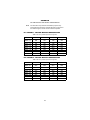
USER
MANUAL
MODELS 2113 & 2115
CopperLink™-T
T1/E1 Extenders
Part# 07M2113-UM
Doc# 03331U2-001,
Rev. A
Revised 1/17/07
An ISO-9001Certified
Company
SALES OFFICE
(301) 975-1000
TECHNICAL SUPPORT
(301) 975-1007
CONTENTS
1.0
1.1
1.2
1.3
1.4
1.5
1.7
Warranty Information .................................................................
Radio and TV Interference............................................................
CE Declaration of Conformity .......................................................
FCC Part 68..................................................................................
Industry Canada Notice ................................................................
Compliance...................................................................................
EMC..............................................................................................
Safety ...........................................................................................
PSTN Regulatory..........................................................................
Service..........................................................................................
Alternate Patton support for Europe, Middle East, and Africa
(EMEA) .........................................................................................
Safety When Working With Electricity ..........................................
2.0
2.1
2.2
General Information.................................................................... 9
Features........................................................................................ 9
Description.................................................................................... 9
3.0
3.1
3.2
Installation.................................................................................
Connecting Power ......................................................................
Power Input Connector ...............................................................
External AC universal power supply...........................................
Connecting the Line Port ............................................................
Connecting the Circuit Interface .................................................
10
11
11
11
12
12
Operation...................................................................................
Front Panel LED Status Monitors ...............................................
Configuration and Dip Switches..................................................
Switch S1-7: Line Build Out........................................................
14
14
15
15
1.6
3.3
3.4
4.0
4.1
4.2
4
4
4
5
5
6
6
6
6
7
7
8
A
A.1
A.2
A.3
A.4
A.5
A.6
A.7
A.8
A.9
A.10
A.11
Specifications ........................................................................... 16
Circuit Rates ............................................................................... 16
Circuit Interface .......................................................................... 16
Circuit Defaults ........................................................................... 16
Circuit Connector ........................................................................ 16
LED Indicators ............................................................................ 16
Power and Power Supply Specifications .................................... 16
Environmental ............................................................................. 17
Transmission Line ....................................................................... 17
Line Coding ................................................................................ 17
Line Interface .............................................................................. 17
Line Physical Connection ........................................................... 17
2
B
Factory Default Dip Switch Configuration.............................. 18
B.1 Switch S1 - Factory Default configuration ................................... 18
B.2 Switch S2 - Factory Default configuration ................................... 18
3
1.0 WARRANTY INFORMATION
Patton Electronics warrants all Model 2113 or 2115 components to be
free from defects, and will—at our option—repair or replace the product
should it fail within one year from the first date of the shipment.
This warranty is limited to defects in workmanship or materials, and does
not cover customer damage, abuse or unauthorized modification. If this
product fails or does not performs as warranted, your sole recourse shall
be repair or replacement as described above. Under no condition shall
Patton Electronics be liable for any damages incurred by the use of this
product. These damages include, but are not limited to, the following: lost
profits, lost savings and incidental or consequential damages arising
from the use of or inability to use this product. Patton Electronics specifically disclaims all other warranties, expressed or implied, and the
installation or use of this product shall be deemed an acceptance of
these terms by the user.
Note
Conformity documents of all Patton products can be viewed
online at www.patton.com under the appropriate product page.
1.1 RADIO AND TV INTERFERENCE
This equipment generates and uses radio frequency energy, and if not
installed and used properly—that is, in strict accordance with the manufacturer's instructions—may cause interference to radio and television
reception. This equipment has been tested and found to comply with the
limits for a Class A computing device in accordance with the specifications in Subpart B of Part 15 of FCC rules, which are designed to provide
reasonable protection from such interference in a commercial installation. However, there is no guarantee that interference will not occur in a
particular installation. If the equipment causes interference to radio or
television reception, which can be determined by disconnecting the
cables, try to correct the interference by one or more of the following
measures: moving the computing equipment away from the receiver, reorienting the receiving antenna, and/or plugging the receiving equipment
into a different AC outlet (such that the computing equipment and
receiver are on different branches).
1.2 CE DECLARATION OF CONFORMITY
We certify that the apparatus identified in this document conforms to the
requirements of Council Directive 1999/5/EC on the approximation of the
laws of the member states relating to Radio and Telecommunication Terminal Equipment and the mutual recognition of their conformity.
4
The safety advice in the documentation accompanying this product shall
be obeyed. The conformity to the above directive is indicated by the CE
sign on the device.
1.3 FCC PART 68
This equipment complies with Part 68 of FCC rules and the requirements
adopted by ACTA. On the bottom side of this equipment is a label that
contains—among other information—a product identifier in the format
US: AAAEQ##TXXXX. If requested, this number must be provided to the
telephone company.
The method used to connect this equipment to the premises wiring and
telephone network must comply with the applicable FCC Part 68 rules
and requirements adopted by the ACTA.
If this equipment causes harm to the telephone network, the telephone
company will notify you in advance that temporary discontinuance of service may be required. But if advance notice isn’t practical, the telephone
company will notify the customer as soon as possible. Also, you will be
advised of your right to file a complaint with the FCC if you believe it is
necessary.
The telephone company may make changes in its facilities, equipment,
operations or procedures that could affect the operation of the equipment. If this happens the telephone company will provide advance notice
in order for you to make necessary modifications to maintain uninterrupted service.
If trouble is experienced with this equipment, for repair or warranty information, please contact our company. If the equipment is causing harm to
the telephone network, the telephone company may request that you disconnect the equipment until the problem is resolved.
Connection to party line service is subject to state tariffs. Contact the
state public utility commission, public service commission or corporation
commission for information.
1.4 INDUSTRY CANADA NOTICE
This equipment meets the applicable Industry Canada Terminal Equipment Technical Specifications. This is confirmed by the registration number. The abbreviation, IC, before the registration number signifies that
registration was performed based on a Declaration of Conformity indicating that Industry Canada technical specifications were met. It does not
imply that Industry Canada approved the equipment.
5
This Declaration of Conformity means that the equipment meets certain
telecommunications network protective, operational and safety requirements. The Department does not guarantee the equipment will operate
to the user's satisfaction. Before installing this equipment, users should
ensure that it is permissible to be connected to the facilities of the local
telecommunications company. The equipment must also be installed
using an acceptable method of connection. In some cases, the company’s inside wiring associated with a single line individual service may
be extended by means of a certified connector assembly (telephone
extension cord). The customer should be aware that compliance with the
above condition may not prevent degradation of service in some situations. Repairs to some certified equipment should be made by an authorized maintenance facility designated by the supplier. Any repairs or
alterations made by the user to this equipment, or equipment malfunctions, may give the telecommunications company cause to request the
user to disconnect the equipment. Users should ensure for their own protection that the ground connections of the power utility, telephone lines
and internal metallic water pipe system, are connected together. This
protection may be particularly important in rural areas.
1.5 COMPLIANCE
EMC
• FCC Part 15, Class A
• EN55022, Class A
• EN55024
Safety
• UL 60950/CSA C22.2 N0. 60950
• IEC/EN60950
PSTN Regulatory
• FCC Part 68
• CS03
• TBR12, & TBR13
• AS/ACIF S031 & S043
6
1.6 SERVICE
All warranty and non-warranty repairs must be returned freight prepaid
and insured to Patton Electronics. All returns must have a Return Materials Authorization number on the outside of the shipping container. This
number may be obtained from Patton Electronics Technical Services at:
• Telephone: +1 (301) 975-1007
• Email: [email protected]
• URL: http://www.patton.com
Technical support is available from 8 AM to 5 PM EST (8:00 to 17:00
UTC-5), Monday through Friday.
Note
Packages received without an RMA number will not be
accepted.
Alternate Patton support for Europe, Middle East, and Africa
(EMEA)
• Telephone support: Standard telephone support is available five days
a week—from 8:00 am to 5:00 pm CET (0900 to 1800 UTC/GMT)—
by calling +41 (0)31 985 25 55
• Fax: +41 (0)31 985 25 26
7
1.7 SAFETY WHEN WORKING WITH ELECTRICITY
• This device contains no user serviceable parts. The
equipment shall be returned to Patton Electronics for
repairs, or repaired by qualified service personnel.
WARNING
• The external AC adaptor shall be a listed limited
power source that incorporates a disconnect device and
shall be positioned within easy reach of the operator.
Ensure that the AC power cable meets all applicable
standards for the country in which it is to be installed,
and that it is connected to a wall outlet which has earth
ground.
• Do not work on the system or connect or disconnect
cables during periods of lightning activity.
In accordance with the requirements of council directive 2002/96/EC on Waste of Electrical and Electronic
Equipment (WEEE), ensure that at end-of-life you separate this product from other waste and scrap and deliver
to the WEEE collection system in your country for recycling.
8
2.0 GENERAL INFORMATION
Thank you purchasing this Patton Electronics product. This product has
been thoroughly inspected and tested and is warranted for one year for
parts and labor. If questions arise while installing or using this product,
contact Technical Support at +1 (301) 975-1007.
2.1 FEATURES
• Easy-to-install T1/E1 Extenders—no configuration required
• Data rates up to 2.048 Mbps in 64-kbps intervals
• Plug ‘n’ Play for easy installations
• LED indicators for Power, Ethernet Link, and Frame
• CE marked
2.2 DESCRIPTION
The Patton Electronics Model 2113/2115 CopperLink™-T provides high
speed 2-wire T1/E1 extension connectivity to ISPs, PTTs, and enterprise
environments using binder group friendly TC-PAM modulation.
Line connection is made with an RJ-45 jack. Models 2113 and 2115 are
powered by an 100/230 VAC (Universal) supply. The NTU features externally-accessible DIP switches, loopback diagnostics, and CopperLink™T Plug ‘n’ Play.
9
3.0 INSTALLATION
Because the CopperLink-T T1/E1 Extenders require no configuration, they
can be installed quickly. Installation consists of the following:
• Connect the power plug (refer to section 3.1, “Connecting Power” on
page 11).
• Connect the line port (refer to section 3.3, “Connecting the Line Port”
on page 12)
Note
See Figure 1 and Figure 2 for the rear-panel connectors
locations.
• Connect the serial port (refer to section 3.4, “Connecting the Circuit
Interface” on page 12).
A
the
e in
US
d
Ma
TX
e
Lin
RX
Line
ce
rfa
Inte
E1 interface
(120 Ohm)
r
we
Po
Power
RX (75 Ohm)
(Data from
G.703/G.704
network)
TX (75 Ohm)
(Data to
G.703/G.704
network)
Figure 1. CopperLink-T Model 2113 rear panel
A
he
de
Ma
in t
US
e
Lin
Line
ce
rfa
Inte
T1 interface
(RJ-48C)
r
we
Po
Power
Figure 2. CopperLink-T Model 2115 rear panel
10
3.1 CONNECTING POWER
CAUTION
The external AC adaptor shall be a listed limited power
source that incorporates a disconnect device and shall
be positioned within easy reach of the operator. Ensure
that the AC power cable meets all applicable standards
for the country in which it is to be installed, and that it
is connected to a wall outlet which has earth ground.
Your CopperLink-T T1/E1 Extender comes with an external AC adaptor
with a detachable power cord.
To connect power to the CopperLink-T:
1. Connect the female plug of the AC power cord to the AC adaptor
provided.
2. Connect the barrel-type connector of the AC adaptor to the Power
connector on the CopperLink-T.
3. Insert the male plug of the AC power cord into the AC power outlet
(100-240 VAC).
4. Verify that the Power LED on the front panel illuminates and remains
lit.
3.2 POWER INPUT CONNECTOR
The CopperLink-T T1/E1 Extender comes with an AC power supply.
• The supplies connection to the CopperLink-T T1/E1 Extender is a
2.5 mm barrel receptacle with the center conductor positive (see
Figure 3).
Figure 3. Power connection barrel receptacle diagram
• CopperLink-T T1/E1 Extender’s rated voltage: 5.0 VDC
• CopperLink-T T1/E1 Extender’s rated current: 1 A DC
External AC universal power supply
• Output from power supply: 5 VDC, 2A
• Input to power supply: universal input 100–240 VAC 50/60 Hz 0.3A
11
CAUTION
The interconnecting cables shall be acceptable for
external use and shall be rated for the proper application with respect to voltage, current, anticipated temperature, flammability, and mechanical serviceability.
3.3 CONNECTING THE LINE PORT
Follow the steps below to connect the CopperLink-T line port:
1. Obtain a single-twisted pair cable with an RJ-45 plug connector at
each end.
2. Plug one end of the cable into the RJ-45 socket (labeled Line) on the
CopperLink-T .
3. When the remote and local extender units synchronize, the frontpanel Link LED will turn on.
3.4 CONNECTING THE CIRCUIT INTERFACE
Your CopperLink-T comes with either an RJ-48C or an RJ-48C and dual
BNC for connection to a T1 or E1:
• Model 2113 - E1: 120-Ohm RJ-48C and dual 75-Ohm BNC connectors
• Model 2115 - T1: RJ-48C
To connect the twisted pair cable to the CopperLink-T serial port:
1. Attach the male connector of the twisted pair cable to the female
connector on the CopperLink-T.
2. Attach the other end of the cable to the serial connector on the local
T1 or E1.
12
Note
The unit marked as 2113/L or 2115/L is configured by
default to accept timing from the T1/E1 circuit. The 2113/
R or 2115/L unit then recovers this timing from the line in
order to ensure synchronization of the T1/E1 circuit over
the extenders.
Model Number
Gaithersburg, Maryland
CopperLink-T T1/E1 Link Extender
Power Input 5VDC, 0.5A
(P) Prod: 2113/L/EUI
(S) Serial Nbr: 0000000000
Lot: M00000
Firm Rev: 1.0.0
Complies with FCC Part 15, Class A and FCC Part 68
Registration No.: 1X1XXXXX111
Patton Electronics
Made in the USA
Figure 4. The label showing the specific model number on the bottom of the unit
13
4.0 OPERATION
Once the CopperLink-T T1/E1 Extenders are properly installed, they
should operate transparently. No user settings required. This section
describes reading the LED status monitors.
4.1 FRONT PANEL LED STATUS MONITORS
Models 2113 and 2115 feature three front-panel LEDs that monitor power,
Ethernet signals, and the CopperLink connection. Figure 5 shows the front
panel location of each LED. Table 1 describes the LED functions.
ra
F
P
ow
e
r
L
in
k
m
e
-T
k™ r
Lin de
er ten
pp Ex
Co Link
/E1
T1
Frame
LED
Link
LED
Power
LED
Figure 5. CopperLink-T T1/E1 Extender front panel
Table 1: Front panel LED description
LED
Power
Link
Frame
Description
When lit, indicates the unit is powered on
• On solid—link is connected
• Off—No signal detected
• Flashing — Data is being transmitted/received
• On solid—T1/E1 frame is connected
• Off — No signal detected
• Flashing — Error detected
14
4.2 CONFIGURATION AND DIP SWITCHES
The CopperLink-T™ T1/E1 Extenders are Plug ‘n’ Play enabled and do
not require any configuration by the user.
Note
The user should NOT change any of the dip switches except
for S1-7 (if necessary). If the user changes the position of any of
the dip switches (except for S1-7), it will affect the operation of
the unit. Refer to Appendix B on page 18 for the factory default
dip switch configuration.
Switch S1-7: Line Build Out
Switch S1-7 defines the shape of the waveform on the T1 or E1 line.
Table 2: S1-7 Default Position
Switch
2113/L/EUI
2113/R/EUI
2115/L/EUI
2115/R/EUI
S1-7
OFF (120)
OFF (120)
ON (0.0dB)
ON (0.0dB)
15
APPENDIX A
SPECIFICATIONS
A.1 CIRCUIT RATES
• Model 2113 - 2.048 Mbps
• Model 2115 - 1.544 Mbps
A.2 CIRCUIT INTERFACE
• E1 (Model 2113) presents G.703/G.704 interface. Either 75 Ohms (unbalanced) or 120 Ohms (balanced). Pins 1 & 2 are Receive. Pins 4 & 5 are
transmit.
• T1 (Model 2115) present T1 interface. Pins 1 & 2 are Receive. Pins 4 &
5 are Transmit.
A.3 CIRCUIT DEFAULTS
• E1 Line Coding = HDB3.
• T1 Line Coding = B8ZS; Line Build Out Rx = Automatic; Line Build Out
Tx = 0.
A.4 CIRCUIT CONNECTOR
• Dual BNC and RJ48C (Model 2113), strap selectable
• RJ48C connector (Model 2115)
A.5 LED INDICATORS
• Three LED indicators: Power, Link, Frame
A.6 POWER AND POWER SUPPLY SPECIFICATIONS
• AC power supply
• Connection to the CopperLink-T T1/E1 Extender requires +5VDC ±5%
DC power (1.0A minimum). Center pin is +5V. The barrel type plug has
a 2.5/5.5/10mm I.D./O.D./shaft length dimensions
• CopperLink-T T1/E1 Extender’s rated voltage: 5.0 VDC
• CopperLink-T T1/E1 Extender’s rated current: 1A DC
16
A.7 ENVIRONMENTAL
• Temperature: 32–122°F (0–50°C)
• Relative Humidity: 5–95%, non-condensing
• Altitude: 0–15,000 ft (0–4,572 m)
A.8 TRANSMISSION LINE
• Single Twisted Pair
A.9 LINE CODING
• TC-PAM (Trellis Coded Pulse Amplitude Modulation)
A.10 LINE INTERFACE
• Transformer coupled, 2500 VRMS isolation
A.11 LINE PHYSICAL CONNECTION
• RJ-45, 2-wire polarity insensitive pins 4 and 5
17
APPENDIX B
FACTORY DEFAULT DIP SWITCH CONFIGURATION
Note
This information is provided for informational purposes only.
These settings should not be changed other than by instructions
from Patton Support, lest the unit be rendered inoperable.
B.1 SWITCH S1 - FACTORY DEFAULT CONFIGURATION
Table 3: S1 Factory Default Dip Switch Configuration
Switch
2113/L/EUI
2113/R/EUI
2115/L/EUI
2115/R/EUI
Switch 1-1
Switch 1-2
Switch 1-3
Switch 1-4
Switch 1-5
Switch 1-6
Switch 1-7
Switch 1-8
ON
ON
ON
ON
ON
OFF
OFF
ON
ON
ON
ON
ON
ON
OFF
OFF
ON
ON
ON
ON
OFF
OFF
ON
ON
ON
ON
ON
ON
OFF
OFF
ON
ON
ON
B.2 SWITCH S2 - FACTORY DEFAULT CONFIGURATION
Table 4: S2 Factory Default Dip Switch Configuration
Switch
2113/L/EUI
2113/R/EUI
2115/L/EUI
2115/R/EUI
Switch 2-1
Switch 2-2
Switch 2-3
Switch 2-4
Switch 2-5
Switch 2-6
Switch 2-7
Switch 2-8
OFF
OFF
OFF
OFF
ON
OFF
OFF
ON
OFF
OFF
OFF
ON
OFF
OFF
OFF
ON
OFF
OFF
OFF
OFF
ON
ON
ON
ON
OFF
OFF
OFF
ON
OFF
ON
ON
ON
18
NOTES
_________________________________________________________
_________________________________________________________
_________________________________________________________
_________________________________________________________
_________________________________________________________
_________________________________________________________
_________________________________________________________
_________________________________________________________
_________________________________________________________
_________________________________________________________
_________________________________________________________
_________________________________________________________
_________________________________________________________
_________________________________________________________
_________________________________________________________
_________________________________________________________
_________________________________________________________
_________________________________________________________
_________________________________________________________
_________________________________________________________
_________________________________________________________
_________________________________________________________
_________________________________________________________
_________________________________________________________
_________________________________________________________
19
NOTES
_________________________________________________________
_________________________________________________________
_________________________________________________________
_________________________________________________________
_________________________________________________________
_________________________________________________________
_________________________________________________________
_________________________________________________________
_________________________________________________________
_________________________________________________________
_________________________________________________________
_________________________________________________________
_________________________________________________________
_________________________________________________________
_________________________________________________________
_________________________________________________________
_________________________________________________________
_________________________________________________________
_________________________________________________________
_________________________________________________________
_________________________________________________________
_________________________________________________________
Copyright © 2007
Patton Electronics Company
All Rights Reserved.
20