1
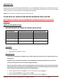
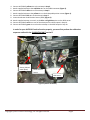
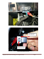
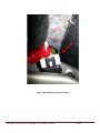
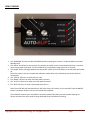
AUTO-BLiP INTELLIGENT DOWNSHIFTS www.AUTO-BLiP.com User Manual 2010-2013 Chevrolet Camaro Version 1.4 Copyright © 2012 Tractive Technology, LLC. All rights reserved. Page 1 WARNING Use of the AUTO-BLiP while driving could lead to an accident and serious injuries. The primary attention of the driver should always be on safe driving. As with any gauge or other instrumentation system in a motor vehicle, the information should be observed as part of a normal sequence of observations performed in the operation of the vehicle. Changes to the settings in the AUTO-BLiP should only be made when it is safe to do so. The driver must remain attentive to driving the vehicle. The mounting of the AUTO-BLiP and the routing of the cable harness connecting it to the vehicle should be done with suitable caution so it does not create an unsafe condition. This includes but is not limited to the following restrictions: Do Not mount the AUTO-BLiP where it can obstruct the view of the driver. Do Not mount the AUTO-BLiP in a manner that could cause it to be propelled through the vehicle during an accident causing injury, such as over or near an air bag. Do Not route the cable in a manner that would interfere with the operation of the vehicle controls. Copyright © 2012 Tractive Technology, LLC. All rights reserved. Page 2 INTRODUCTION Congratulations on your purchase of the AUTO-BLiP for use on the 2010-2013 Chevrolet Camaro. Please take the time to read the entire instruction manual before attempting to install. DO NOT adjust the AUTO-BLiP until you have thoroughly read the instruction manual and the unit is fully installed and calibrated. NOTICE: The AUTO-BLiP is intended for racing or off-road use only. PLEASE READ ALL INSTRUCTIONS BEFORE BEGINNING INSTALLATION! WE STRONGLY SUGGEST THAT AN EXPERIENCED TECHNICIAN INSTALL THE AUTO-BLiP PRODUCT! INSTALLATION INSTRUCTIONS THE IGNITION MUST BE TURNED OFF BEFORE INSTALLATION! Signal Description Ground 12v Brake sensor Clutch sensor Accelerator Pedal Position Sensor 1 (APPS) Accelerator Pedal Position Sensor 2 (APPS) AUTO-BLiP Harness color code Black White Blue Yellow Red Camaro wiring color code White (clutch sensor) Red/white (OBDII connector) Yellow Yellow Blue Green Light blue Tools needed: Needle nose pliers Digital Multimeter (DMM) - optional Signal connections: Note: Before connecting the AUTO-BLiP to your vehicle, make sure the wire harness is routed away from any moving parts! Installation tip(s): To facilitate installation, we recommend disconnecting the OEM wire harness from the sensor(s). This will make it easier to install the supplied wiretaps. Note: For this vehicle in order to access the clutch position sensor wires (Figure 4), the connector must first be disconnected from sensor (Figure 3). A small flat blade screw driver can be used to help release the connector that is facing in the direction of the brake pedal assembly (Figure 1). 1. Attach supplied wiretap to the white wire on the clutch position sensor (Figure 1). 2. Connect AUTO-BLiP black wire to the wiretap in Step 1. 3. Attach supplied wiretap to the yellow wire on the clutch position sensor (Figure 1). Copyright © 2012 Tractive Technology, LLC. All rights reserved. Page 3 4. 5. 6. 7. 8. 9. 10. 11. 12. Connect AUTO-BLiP yellow wire to the wiretap in Step 3. Attach supplied wiretap to the red/white wire on the OBDII connector (Figure 2). Connect AUTO-BLiP white wire to the wiretap in Step 5. Attach supplied wiretap to the yellow wire on the brake pedal position sensor (Figure 1). Connect AUTO-BLiP blue wire to the wiretap in Step 7. Locate Accelerator Pedal Position Sensor (APPS) (Figure 1). Attach supplied wiretaps, one each, to the blue and light blue wires on the APPS sensor. Connect AUTO-BLiP red wire to one of the wiretaps on the APPS output in Step 10. Connect AUTO-BLiP green wire to the other wiretap on the APPS output in Step 10. In order for your AUTO-BLiP unit to function properly, you must first perform the calibration sequence outlined in the CALIBRATING UNIT section!!! Clutch Position Sensor (behind metal plate) Brake Position Sensor APP Sensor Figure 1 (Sensor Locations) Copyright © 2012 Tractive Technology, LLC. All rights reserved. Page 4 Figure 2 (OBDII Power connection) 1) Slide white piece to release safety lock 2) Press on to release connector from sensor Figure 3 (Clutch & Brake connector) Copyright © 2012 Tractive Technology, LLC. All rights reserved. Page 5 Figure 4 (Clutch position sensor connector) Copyright © 2012 Tractive Technology, LLC. All rights reserved. Page 6 HOW IT WORKS 1. The “DURATION” dial sets the desirable RPM blip level by opening the throttle. Turn dial clockwise to increase RPM blip level. 2. The “DELAY” dial allows for the insertion of a constant time delay from the time a downshift event is sensed to when the unit blips the throttle. Turn dial clockwise to increase delay. Range from 0 to 0.5 seconds. 3. The ON/OFF button will toggle between the ON and OFF mode. The unit will default to the ON state upon power up. Note: This button is also use to enable the calibration mode. Refer to the Calibrating Unit section below for more details. 4. The “STATUS” LED turns on when the unit is ON. 5. The “BRAKE” LED turns on when the brake pedal is pressed. 6. The “CLUTCH” LED turns on when the clutch pedal is pressed. 7. The “BLIP” LED turns on when a throttle blip event occurs. Note: The AUTO-BLIP will automatically turn OFF after 6 hours of inactivity. It will remain OFF until the ON/OFF button is pressed or power to the unit is removed and re-applied. The AUTO-BLiP monitors your automobile’s accelerator pedal, brake pedal, and clutch pedal, blipping the throttle only when the clutch pedal is being depressed while simultaneously braking. Copyright © 2012 Tractive Technology, LLC. All rights reserved. Page 7 CALIBRATING UNIT In order for your AUTO-BLiP unit to function properly, you must first perform the calibration sequence outlined in this section!!! 1. Turn on ignition, but do not start engine. AUTO-BLiP “STATUS” LED light will light up. If not, turn ignition off and verify the power supply and ground connectors are fully seated. 2. Set both the “DURATION” and “DELAY” adjusting dials on the AUTO-BLiP unit to the 12 o’clock position. 3. To enter the calibration mode, press and hold down the ON/OFF button (about 10 seconds) until the “STATUS” LED continuously blinks (1) time followed by a short pause. 4. Fully press and hold down the accelerator pedal. While holding the accelerator pedal wide open, press and release the ON/OFF button once, continue to hold the accelerator pedal down. This step records your vehicle’s full open throttle pedal position. 5. At this point the “STATUS” LED light will blink (2) times followed by a short pause. Completely release the accelerator pedal. With the accelerator pedal completely released, press and release the ON/OFF button once. This step records your vehicle’s close throttle pedal position. 6. At this point the “STATUS” LED light will blink (3) times followed by a short pause. Slightly press the brake pedal. With the brake pedal slightly pressed, press and release the ON/OFF button once, continue to hold the brake pedal down. This step records your vehicle’s brake pedal pressed position. (See Note 1) 7. At this point the “STATUS” LED light will blink (4) times followed by a short pause. Completely release the brake pedal. With the brake pedal completely released, press and release the ON/OFF button once. This step records your vehicle’s brake pedal released position. 8. At this point the “STATUS” LED light will blink (5) times followed by a short pause. Completely press the clutch pedal. With the clutch pedal completely pressed, press and release the ON/OFF button once, continue to hold the clutch pedal down. This step records your vehicle’s clutch pedal pressed position. (See Note 1) 9. At this point the “STATUS” LED light will blink (6) times followed by a short pause. Release the clutch pedal approximately ½” to 1” from the full pressed position. With the clutch pedal released approximately ½” to 1”, press and release the ON/OFF button once. This step records your vehicle’s clutch pedal released position. 10. This completes calibration of the AUTO-BLiP unit! Note 1: This vehicle is equipped with an analog position sensor. This allows the user to set where in the pedal travel position the AUTO-BLiP blips the throttle. Note: When properly calibrated, the “BRAKE” and “CLUTCH” LEDs will turn on when the corresponding pedal is pressed. The AUTO-BLiP features a diagnostic function that will warn the user when the AUTO-BLiP’s calibration routine fails to properly recognize the accelerator pedal position sensor (APPS), BRAKE, and/or CLUTCH signals. Failures related to the BRAKE and/or CLUTCH will prevent the unit from exiting the calibration sequence. This is done to prevent AUTO-BLiP from blipping the throttle at the incorrect time. When a failure is detected the AUTO-BLiP will continuously blink the “BRAKE”, “CLUTCH”, and/or “BLIP” LEDs, signaling a failure during calibration of the respective signals. Press and release the ON/OFF button once to re-start the calibration sequence from the beginning. Copyright © 2012 Tractive Technology, LLC. All rights reserved. Page 8 TECH SUPPORT In the event of a malfunction, please check the following: 1. Turn off ignition then verify all connectors are fully seated. 2. Make sure the unit is properly powered. When unit is properly powered the “STATUS” LED will remain continuously lid. 3. Be sure the unit has been calibrated, as outlined in the calibration section, according to your vehicle’s model and year. 4. Check harness for cuts, scrapes or abrasions. 5. Call technical support at 480-788-6748 Tractive Technology, LLC P.O. Box 93562 Phoenix, AZ 85070-3562 [email protected] Copyright © 2012 Tractive Technology, LLC. All rights reserved. Page 9 AUTO-BLiP LIMITED WARRANTY Tractive Technology, LLC warrants this product against defects in material and workmanship for the period of 90 days. The warranty period begins with the date of original retail purchase. This limited warranty is made only to the original end user purchaser ("you") of the product and does not extend to any subsequent purchasers or owners of the product. The "original end user" is the first user to put the product into service in any fashion. It is your responsibility to establish the warranty period by verifying the original purchase date. If you discover a defect, Tractive Technology, LLC will, at its option, repair or replace this product with a new or reconditioned product at no charge to you, provided you return it during the warranty period, with transportation charges prepaid, to Tractive Technology, LLC. (You can obtain additional information by contacting Tractive Technology, LLC at the address printed on the card). Please attach your name, address, telephone number, and a copy of the bill of sale as proof of date of original retail purchase, as well as a detailed description of the problem for which service is requested. Prior to returning the product, you must obtain from Tractive Technology, LLC a Return Merchandise Authorization Number (RMA#). You are responsible for packing the product to be returned. If the repairs are covered by the Limited Warranty and if the product was properly shipped to Tractive Technology, LLC, Tractive Technology, LLC will pay the return shipping charges. This warranty applies only to AUTO-BLiP product manufactured by Tractive Technology, LLC that can be identified by the "AUTO-BLiP" trademark, trade name, or logo affixed to them. This warranty does not cover damage resulting from an accident, misuse, abuse, or neglect and/or damage during any type of transportation resulting from improper packaging; damage to any product which has been altered in any fashion, including the alteration or removal of any Tractive Technology, LLC serial number; damage resulting from causes other than product defects, including and not by way of limitation, lack of technical skill, competence, or experience of the user, and/or failure to use the product in accordance with the instructions provided in the User's Manual; and service performance by an unauthorized person or entity. Any implied warranties including fitness for use and merchantability are limited in during to the period of the expressed warranty set forth above. The remedies provided under this warranty are exclusive and in lieu of all others. Tractive Technology, LLC hereby expressly disclaims liability and shall not be responsible for incidental, consequential and contingent damages or any kind of nature, including, without limitation: damages to persons or property, whether a claim for such damages is based upon warranty, contract, tort or otherwise; damages to persons or property, whether a claim for such damages is based upon warranty, contract, tort or otherwise; damages due to or arising out of the loss of date; or lost of profits. Tractive Technology, LLC shall not be responsible for any damages caused by the presence of error or omission in any of its manuals, instructions or related materials. Tractive Technology, LLC Attn: Warranty Claims P.O. Box 93562 Phoenix, AX 85070-3562 Copyright © 2012 Tractive Technology, LLC. All rights reserved. Page 10