1
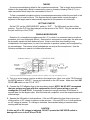
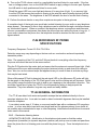
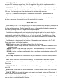
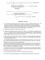
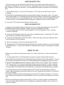
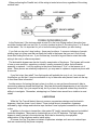
CMS-25 COUNTERMEASURES SET INSTRUCTION MANUAL The CMS-25 Countermeasures Set consists of the following instruments and accessories: 1. 2. 3. 4. 5. 6. 7. 8. TD-62 Transmitter Detector P-01 Wideband RF Probe P-02 Infrared Probe P-03 Line Driver Probe P-04 Microwave RF Probe TT-46 Advanced Wiretap Detector Earbuds Various cords, adaptors and Padded Carrying Case FINDING BUGS HOME/OFFICE Transmitters are frequently concealed in various household or office fixtures. The most common are electric sockets or cube taps. In this configuration, normal AC power is supplied directly to the transmitter which permits permanent installation. This means that all lamps and appliances (radios, TV, clock, desk calculator, etc.) should be checked carefully. Another type is the drop transmitter. These are used where quick installation is required. Being battery operated, they have a finite operating life which requires that they be retrieved for battery replacement or abandoned. These transmitters are often pre-concealed in objects such as picture frames, pens, desk sets, cigarette lighters and ash trays. Body transmitters are battery operated, usually with a higher output power than the drop transmitter. They are designed to be carried into a target area on a person. VEHICLES While voice bugs can be installed in a vehicle, probably the most common type is the tracking transmitter (bumper beeper). Most of these are the burst type which means that RF is transmitted in short bursts rather than continuously. These transmitters can be powered either by their own battery pack or by the vehicle battery. The transmitters powered by the vehicle battery may have a much higher output power and, of course, a longer useful life. The main advantage of the battery pack unit is that it is quicker to attach. To check a vehicle for bugs, turn the ignition on, but don’t start the engine (Ignition noise will thoroughly confuse the TD-62). Using the P-01 probe slowly sweep the vehicle inside and out, (be sure to sweep carefully underneath the vehicle). Because of the limited brightness of the indicator LEDs, it would be better to do this away from direct sunlight, if possible. Pay particular attention to the meter. Brief flashes at the next higher level could indicate a burst type bumper beeper. ABOUT THE TD-62 The TD-62 Transmitter Detector is a complex piece of countermeasures test equipment. The TD-62 must be used in conjunction with one of the (4) probes described below: • • • • P-01 - Wideband RF Probe (up to 2.5 GHz) P-02 – Infrared Probe (Laser Detector) P-03 – Line Driver Probe (Detects hard wired microphones) P-04 – Microwave RF Probe (2.5 GHz to 6 GHz) ___________________ Description of Functional Buttons: Power Button – Upper right corner turns the unit on and off. If the unit is left on, it will automatically shut off in 15 minutes if no other button is pushed (this time is adjustable). Menu Button – To scroll through the menu options continue to push the menu button within 5 seconds. Use the up or down arrows to change the selection. First Push – This selection allows the user to change from the Detect mode to the Verify mode. The Detect mode is used to locate transmitters and the Verify mode is used to determine if audio is being transmitted. Second Push – This will allow you to change from high sensitivity to low sensitivity by using the up and down arrows. This will aide in locating bugs. Once you have a strong signal, switch to low sensitivity to help pinpoint the location of the transmitter. Third Push – This will adjust the brightness of the backlight by using the up and down arrows. Fourth Push – This will adjust the contrast of the display by using the up and down arrows. Fifth Push – This allows you to adjust the time set for the auto off feature (set to 15 minutes at the factory) however, it is adjustable by using the up and down arrows. Sixth Push – Shows remaining battery voltage. Arrow Buttons – The use of these buttons by themselves will allow the user to adjust the volume of the TD-62. The battery can be accessed through the sliding cover on the bottom end. *** DO NOT disconnect the battery by pulling against the wires. Damage caused in this manner will not be covered by the warranty. *** The battery should only be replaced with a 9V DC alkaline or equivalent battery. The top of the unit has two jacks. The center jack is used to attach one of the four probes. The jack to the left side is used for the included ear bud (under reduced volume). SUMMARY & LIMITATIONS The best way to become proficient with the TD-62 is to practice. A reasonable and readily available practice transmitter is a child’s 49 MHz walkie-talkie. For the most effective practice, get someone else to hide the test transmitter for you. The person hiding the transmitter should be reasonable. Just tape down the transmit button, turn the unit on and have someone hide it. Then practice finding the transmitter using both the DETECT and VERIFY modes. The clicking (in the DETECT mode) or the squeal (in the VERIFY mode) can alert the eavesdropper that you’re on to him. For this reason, we have provided an earbud jack (to be plugged in on the top left corner of the TD-62). Just plug in the supplied earbud and you’ll be able to hear the clicking in the DETECT mode with no trouble. In the VERIFY mode, keep the volume turned down to protect your hearing in case a feedback squeal is set up. P-01 PROBE SPECIFICATIONS Frequency Response: Covers 5 MHz to 2.5 GHz. Detection range may vary depending on factors such as: construction, antenna placement, furnishings, and most importantly transmitter power. Plug the P-01 probe into the center jack and extend the telescoping antenna. Walk slowly around the room while sweeping the probe (antenna) slowly up and down from ceiling to floor. Also, turn on the various lamps and appliances as you come to them to activate any bugs that may be hard wired. When a RF field is detected, the red signal LED on the Wideband RF probe will light, the bar graph in the display of the TD-62 will grow in size and the clicking rate will increase. At this time, slowly sweep the probe from side to side to get a bearing on the transmitter’s direction. This would be a good time to place the TD-62 in the low sensitivity setting to help pinpoint the transmitter. Pay close attention; bugs are very small and easily hidden. Never end the sweep when you find a bug. When someone is serious about invading your privacy they will seldom rely on just one bug in one room. P-02 INFRARED PROBE SPECIFICATIONS Field of View: 50 degrees Spectral Peak: 880 nm (infrared) THEORY Light beams, especially lasers, provide an excellent method for carrying audio intelligence. The light beam can be visible or invisible (as in infrared). They can carry conversations for long distances with most manufacturers claiming a range of several kilometers. And most importantly, modulated light attacks are often not considered by individuals performing countermeasures checks. This can be a fatal oversight from a security standpoint. The P-02 is a special probe, designed for use with the TD-62 Transmitter Detector, which allows the technician to search for sources of infrared (IR) transmissions. In the case of amplitude modulated or pulse frequency modulated sources, the technician can actually listen and determine whether the beam is carrying voice transmissions or other intelligence. Light beams carrying room audio can be very narrow. They can shoot through windows and reflect off glass, metallic and other bright surfaces. This can be readily demonstrated with a TV remote control infrared device. Try pointing it at different surfaces around the room and notice how the TV can be controlled by reflections from pictures and windows. Narrow light beams are very directional (line of sight) – a point the countermeasures technician should keep in mind. DETECTION Insert the P-02 probe into the center jack on the TD-62. Turn on theTD-62. Any number of tests can be made to verify that the unit is working. In the Detect mode, when the probe is pointed at incandescent or fluorescent lights, the meter signal will increase and the “clicking” rate will also increase. In the Verify mode, a hum or buzzing sound will be heard. When an IR signal is detected, the red signal LED on the IR probe will light, the bar graph in the display of the TD-62 will grow in size and the clicking rate will increase. At this time, slowly sweep the probe from side to side to get a bearing on the transmitter’s direction. When sweeping for IR transmitters pay particular attention to window openings – remember that light travels in a straight line. An unmodulated IR beam will cause the signal to increase and (in the Verify mode) a rushing noise will be heard in the speaker or earbud. A modulated IR beam will also cause signal to increase. In addition, some type of audio will be heard in the Verify mode. Depending on the type of modulation, you will hear either baseband audio or some type of tone. High speed data (above an audio rate) will give a rushing sound. P-03 LINE DRIVER PROBE SPECIFICATIONS Current: Limited to 8 mA maximum Input impedance: 8K Ohms Indications: Red LED – Lights when more than 1.4 volts AC or DC is present on the wire pair under test. Green LED – When the Line Driver switch is operated, this LED glows if 400 uA or more is being drawn by the wire pair under test. The more current that is drawn, the brighter the LED will grow. Controls: LINE DRVR/OFF – This switch applies a voltage to the wire pair under test to turn on voltage activated microphones. *** CAUTION *** Never push the Line Driver switch on if the Line Driver LED is RED. This indicates a voltage present on the wire pair. Pushing the line driver while there is a voltage on the line will damage the P-03 and TD-62. Any damage caused in this fashion will not be covered under the product warranty. The use of a digital multimeter or other voltage indicating device is highly recommended before connecting the P-03 to any wire pair. A/B – This switch reverses the polarity of the line connections for detecting DC voltages and for reversing the polarity of the line driver voltage to aid in detecting polarity sensitive devices. THEORY A common eavesdropping attack is the concealed microphone. This is simply a microphone, hidden in the target area, which is connected by wires to a nearby Listening Post (L.P.) or a radio transmitter which relays the conversation to the L.P. To find a concealed microphone during a countermeasures sweep, either the mic itself or the wires leading to it must be found. This requires that all suspect wires running through or adjacent to the target area be electronically inspected for the presence of room audio. GETTING STARTED On the P-03, set the LINE DRVR/OFF switch to “OFF”. The A/B switch can be in either position. Plug the P-03 into the probe jack on the top end of the TD-62. Plug the ear bud into the jack on the top of the TD-62. FINDING MICROPHONES Detection of a concealed microphone and the L.P. to which it is connected can be a tedious procedure, but is not technically difficult. Once audio is recovered on a wire pair, the wire must be physically traced until both ends are found. Keep in mind that wires leading to any loudspeaker in the target area (i.e. part of an intercom or speaker system) can be exploited by an eavesdropper. The reason is that loudspeakers can act just like microphones. Use the following procedures to search for hidden microphones. 1. Turn on a sound source (such as a radio) in the target room. Next, turn on the TD-62 and set the MODE switch to “VERIFY”. Ignore any indications on the LED meter. Make sure the LINE DRVR LED switch on the P-03 is “OFF”. 2. Connect the P-03 alligator clips to the wires being tested. NOTE: We DO NOT recommend that you perform any tests with this equipment on live AC power wiring or you will damage the P-03 and TD-62. If necessary, scrape just enough insulation off the wires to expose them for the alligator clips. After the tests are completed, cover the scraped areas with electrical tape. 3. Operate the A/B switch to both positions. If the red LED above the line driver comes on in either position, a DC voltage is present on the wire pair. If the red LED is on in both positions, an AC voltage is present. If a voltage is indicated, use standard safety procedures when working with the wire pair. CAUTION If either an AC or DC voltage is indicated, DO NOT operate the LINE DRVR switch or damage will occur to the P-03 and TD-62. 4. Turn up the TD-62 volume control to a comfortable level and listen for room audio. If the line has no voltage present, turn on the LINE DRVR switch to apply voltage to the wire pair. Operate the A/B switch to both positions and listen for room audio. Shield the green LED from room light and observe it for any glow of light. If you see any light from this LED that means that current is flowing in the wire pair and a listening device could be connected to the wires. The brightness of the LED indicates the level of current that is flowing. 5. Perform the above checks on any other suspicious wire pairs in the target area. A complete check of the target room would also include listening for room audio on any telephone wires present. The reason for this is that a telephone can be modified through a technique known as “hook switch bypass”. When so modified, the telephone acts as a microphone and intercepts all room conversations and passes them down the phone line even while the phone is hung up. If room audio is heard on the phone line, the telephone should be checked for the hook switch bypass attack. P-04 MICROWAVE RF PROBE SPECIFICATIONS Frequency Response: Covers 2.5 GHz TO 6 GHz. Detection range may vary depending on factors such as: construction and most importantly transmitter power. Note: The operation of the P-01 and the P-04 are identical in everything other than frequency response and should be used in the same method. Plug the P-04 probe into the center jack and ensure that the antenna is secured finger tight. Walk slowly around the room while sweeping the probe (antenna) slowly up and down from ceiling to floor. Also, turn on the various lamps and appliances as you come to them to activate any bugs that may be hard wired. When a Microwave RF field is detected, the red signal LED on the Microwave RF probe will light, the bar graph in the display of the TD-62 will grow in size and the clicking rate will increase. At this time, slowly sweep the probe from side to side to get a bearing on the transmitter’s direction. This would be a good time to place the TD-62 in the low sensitivity setting to help pinpoint the transmitter. Pay close attention; bugs are very small and easily hidden. TT-46 GENERAL INFORMATION The TT-46 can detect both series and parallel wiretaps that are attached directly to the on premises telephone line. It can also be used to detect hookswitch bypasses that may be installed inside the telephone. It can detect series taps of 10 ohms or more and parallel taps with a resistance of 65 megohms or less. In a four wire cable (used with most single and two line phone systems) it can check all six possible wire combinations for taps or other tampering. Listed below are definitions for several terms used in this manual. BUG – Clandestine listening device. HOOKSWITCH BYPASS – Modification to the telephone instrument so that the carbon microphone (transmitter) or dynamic earphone (receiver) will pick up room sounds and pass them down the phone line to a listening post even with the phone hung up. Turns the telephone into a bug. PARALLEL TAP – Connected across both wires of a pair. Usually used to activate a tape recorder. DC resistance ranges from 10 to 35 megohms. May also be a radio transmitter, in which case, a separate battery would be required for powering the transmitter. SERIES TAP – Usually a radio transmitter. Obtains power from the telephone line to which it is attached. It is installed in series (in line with one wire). Generally has a DC resistance of 70 to 300 ohms. And although rare it can also be used to activate a tape recorder. WIRETAP – Clandestine interception of a telephone conversation. Operates when the telephone is in use. We recommend that you perform the tests in the order given in the manual. While the tests can be done in any order, the manual lays out the most efficient procedure. USING THE TT-46 Install a battery in the TT-46 (alkaline only) if one has not already been installed. To access the battery compartment, insert a small flat blade screwdriver in the screwdriver slot at the bottom of the face panel and pry up. The front panel will pop up. After installing the battery, replace the front panel, pressing down on its edges until it snaps into place. The telephone cable generally used as inside wiring for single and two line service has four wires arranged in two pairs: red/green and black/yellow. These four wires give six possible pair combinations that should be checked (r/g, r/y, r/b, g/y, g/b and y/b). Through the use of the various switches on the TT-46, you will be able to test all six combinations for both series and parallel taps and other forms of tampering. The following is a description of the functions of the switches and indicators on the TT-46. Please refer to your unit for their locations. MODE: Selects the type of test to be performed from the four below. PARALLEL: Checks for taps and bugs wired across the pair. Can detect resistances of 65 megohms or less. SERIES: Checks for taps and bugs wired inline. Detects resistances of 10 ohms or more. VERIFY: Lets you listen to a wire pair for the presence of room audio. DRIVER: Applies a voltage to a wire pair to turn on a voltage operated device such as a FET microphone. TEST 1/TEST 2: Reverses the connection to the pair under test. Useful for detecting certain polarity sensitive devices. PAIR: Selects one of six combinations for testing. All tests should be applied to all pairs. VOLUME: Combination switch/volume control for the audio amplifier used in the Verify and Driver tests. PARALLEL LED: Glows red if the Parallel test detects 65 megohms or less. Glows green if the test is OK. SERIES LED: Glows red if the Series test detects 10 ohms or more. Glows green if the test is OK. PUSH TO TEST: Use to apply the test to a wire pair in the Parallel, Series and Driver tests. It has no function in the Verify test mode. Connect the test cable by plugging it into the 5-pin jack located at the hinge end of the unit. Be sure the plug is completely seated in the jack. PARALLEL TAP TEST 1. Disconnect the inside wiring at the protector block or Telephone Network Interface (TNI). The protector or TNI can be located inside or outside the building and is the point of separation between the inside wiring and the phone company line. Make a note of the wire colors and connections so you can reconnect them properly when you are finished. With the TNI simply unplug the modular plug to disconnect the inside wiring from the phone line. 2. Disconnect all telephones, answering machines, etc. 3. Set the TT-46 switches as follows: Pair to “R-G” Volume to “OFF” Mode to “parallel” and Test to “Test 1”. Connect the unit to the inside wiring at any convenient point. If your building does not use modular jacks, it will be necessary to connect the TT-46 using the coupler and cord with alligator clips. Connect color to color, i.e., red to red, etc. 4. Push and hold down the PUSH TO TEST (PTT) button. The Parallel LED should glow green. While continuing to hold down the PTT button, rotate the Pair switch through all six positions. Then release the PTT switch. If the Parallel LED flashed red briefly, some additional tests are necessary. Here’s why - 100 feet of inside wiring has about .002 uF of stray capacitance between any two wires. This stray capacitance could cause the LED to briefly flash red. To check for the presence of a capacitively coupled parallel wiretap, press and hold down the PTT switch again. Rotate the Pair switch through all six positions from R-G to Y-B and back again four times without releasing the PTT switch. If any of the pair combinations still flash red, that is an indication of a capacitively coupled tap. Using this test method, the stray wiring capacitance is charged by the test set and that charge will remain for a period of time, but a capacitively coupled tap will discharge between rotations of the pair switch, causing the LED to flash red. 5. Do the same tests as #4 above with the Test switch in the Test 2 position. 6. Leave the TT-46 and inside wiring set up for the Parallel test and perform the Verify test. WIRE PAIR VERIFY TEST In this test mode you will check the inside wiring for room audio that could be present if a microphone is attached to one of the wire pairs. Technically, this would not be a wiretap, but a bug. However, the result is the same – your confidential information is passed on to a listening post. 1. Set the Mode switch to “Verify” the Pair switch to “R-G” and turn on the Volume to about midrange. 2. Move the Pair switch through all six positions while listening to the audio output. It’s a good idea to play a radio or TV in the target room while doing a sweep. This gives you a known sound source, it will also turn on sound activated bugs. If you hear room audio or a feedback squeal from the test set, it is an indication that a microphone is attached to one of the wire pairs. 3. Leave the TT-46 connected and perform the Driver test. WIRE PAIR DRIVER TEST In this test you will apply voltage to each pair to turn on voltage operated devices such as FET (Field Effect Transistor) microphones. Again, these are not wiretaps, but bugs. 1. Turn the Mode switch to “Driver” the Pair switch to “R-G” Test switch to “Test 1” and the Volume to midrange. 2. Press the PTT switch and listen for room audio or feedback squeal. Release the PTT switch and move the Pair switch to the next position. 3. Do step 2 for each position of the Pair switch. When all six pairs have been checked, return the Pair switch to the R-G position. 4. Set the Test switch to Test 2 and repeat steps 2 and 3. 5. Disconnect the TT-46 and return the inside wiring to its normal condition or go on to the Series test described next. If you got an indication of a parallel tap or bug, go to the pages on locating wiretaps. SERIES TAP TEST In this test, you will be checking each wire pair for a series (in line) tap. Follow the steps listed below. 1. At the protector block or TNI (illustration on page 19), make sure the inside wires are disconnected from the phone line as discussed earlier and short all four lines together. This can be done by connecting all four wires to the same binding post and tightening the nut or screw. 2. Set the TT-46 switches as follows: Mode to “Series” Test to “Test 1” Pair to “R-G” Volume to “Off”. Connect the TT-46 in turn to each inside wiring connection point (B, C, and D, on page 27). It is important to run the test at each jack so that each leg or branch is tested. This was not necessary in the Parallel test since all branches or legs are automatically tested in parallel. 3. At each connection point, push and release the PTT switch for each position on the Pair switch. Before leaving one connection point for the next, repeat the tests with the Test switch in the Test 2 position. For each pair, the Series LED should glow green when the PTT switch is pressed. If it is red for any of the tests, this means the loop resistance is over 10 ohms and is an indication of a series tap. 5. Return the inside wiring at the protector block or TNI to its normal condition (reconnect each wire to its proper place). Reconnect your telephones, answering machines, etc. to return your system to normal. HOOKSWITCH BYPASS TEST VERIFY MODE This test lets you check your telephone for hookswitch bypass tampering. In this test, you will use the dual modular coupler. Phones without modular plugs can be tested using the in-line coupler and modular cord with alligator clips. 1. On the TT-46 set the switches as follows: Mode to “Verify” Test to “Test 1” Pair to “R-G” and Volume to midrange. 2. Unplug the telephone to be tested from its wall jack and plug the dual coupler into the jack in its place. Then plug the phone into one jack of the dual coupler and the TT-46 into the other jack. 3. Lightly tap the phone housing with a pen or pencil. If you hear the tapping in the TT-46 speaker, it is an indication that the phone is capable of transmitting room audio down the line when the phone is hung up. You may also hear a feedback squeal, depending on the sensitivity of the hookswitch bypass. 4. Rotate the Pair switch through all six positions while repeating step 3. 5. Turn off the TT-46, remove the dual coupler and reconnect the phone to its wall jack. If you have other phones, answering machines, etc., they should be checked in the same manner as outlined above. If your telephone does not have a modular plug, it can be tested in the same manner as above, but you will have to open the connector block or jack where the phone is connected and use the modular coupler and cord with alligator clips to make your connections. Be sure to connect red to red, etc. HOOKSWITCH BYPASS TEST DRIVER MODE This test lets you check your phones for hookswitch bypass tampering without having the phone connected to an active line. 1. On the TT-46 set the switches as follows: Mode to “Driver” Test to “Test 1” Pair to “R-G” and the Volume to midrange. 2. Plug the phone into one jack of the dual coupler and the TT-46 into the other dual coupler jack. 3. Press the PTT switch while lightly tapping the phone housing with a pen or pencil. If you hear the tapping in the TT-46 speaker, it is an indication that the phone is “hot on hook”. Release the PTT switch. 4. Rotate the Pair switch through all six positions while repeating step 3. 5. Place the test switch in the “Test 2” position and repeat steps 3 and 4. LOCATING WIRETAPS AND WHAT TO DO IF YOU FIND ONE All of the wiretaps can be located by close physical inspection of the inside wiring. Remember, if someone installed it, you’ll be able to find it. Note that series taps can be made very small. A favorite way to disguise one is to wrap it with tape so it looks like a wire splice or connection. There are two basic ways phone systems are wired. In the loop method, each phone is connected at different points to the same wire run. In the branch method, a separate wire pair is run to each phone location from the TNI. When performing the Parallel test, all the wiring is tested at one time, regardless of the wiring method used. In the Series test, if the test was made at point D in the Loop Wiring method, the entire loop would be checked with one test. But, if you only checked at point C, the wiring from C to D would not be tested. So, it is important for you to know the wiring plan before you start testing. If you find one tap, don’t stop looking – there may be others. A common technique of people planting taps is to place one that can easily be found in the hopes that you won’t look for any more after finding the first one. If you find one tap, it would be a good idea to retest the inside wiring to be sure no others are present. The hookswitch bypass can also be found by examination of the phone. The bypass will consist of one or more resistors, capacitors or diodes, usually connected to either the hookswitch assembly or network. Look for anything in the phone that doesn’t “fit in” or that seems out of place. Since phones are relatively inexpensive, you may want to replace a suspicious phone with a new one. If you find a tap, then what? Your first impulse will probably be to rip it out – but stop and think before you do that. It may be worthwhile to try to determine who planted it and use the tap to feed them false information. Another reason for leaving the tap in place is so that you can get law enforcement‘s help in prosecuting whoever placed the illegal tap. Most law enforcement departments do not have the manpower to help if you just suspect a tap, but if you have the physical evident they should be willing to investigate. Remember, wiretapping is a Federal crime as well as a violation in most states. LIMITATIONS While the Tap Trap will detect the most common on-premises wiretaps and hookswitch bypasses, there are some it won’t detect. These include drop-in transmitters, bypasses activated by high voltage and inductive taps that don’t have a physical connection to the phone or line. In addition to the drop-in transmitter, other series RF (radio) transmitter taps can be installed inside the telephone. These can be located with any of our RF detectors. The high voltage bypass is rarely used as is the inductive tap. Both can be located by close physical examinations of the telephone and/or inside wiring. Of course, the Tap Trap does not detect off-premises wiretaps such as court ordered taps that are connected by the phone company.