1
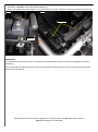
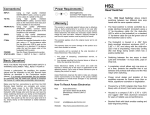
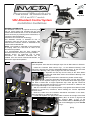
Powered Wheelchairs May 2012 IPC-S and IPC-T models VR2 Attendant Control System Installation Guidelines GENERAL INFORMATION The Attendant Control is an optional accessory that Fig.1 may be factory fitted and supplied with the new Invicta Powered Wheelchair, or can be installed as a retro-fit accessory by following these instructions, in conjunction with the attached instructions from PG Drives Technology. Attendant This Attendant Control, is intended for use, in Control with conjunction with the PG Drives Technology, VR2 Mounting JSM Remote Controller, fitted as standard to the Stem Invicta Powered Wheelchair. NOTE: The installer is reminded of the importance of keeping cable runs neat and as close to the wheelchair as possible. It is recommended that the User vacates the wheelchair whist this accessory is being installed. Although shown for right-hand use in these instructions, the Attendant Controller can be installed onto the Invicta Powered Wheelchair, for either left or right-hand operation. Kit Components Stem Mount Cable Ties Intermediate Cable Plug (3) Plug (1) Socket (1) Alternative Control Knob Socket (2) INSTALLATION Tools Required: 3mm and 5mm Hexagon Keys. Pair of Side-cutters or Scissors Fig.2a Backrest Bracing Tube (c) (b) (a) Fig.3a Install the Controller Stem Mount Fig.1, to the Backrest Bracing Tube (Fig.2a) by removing the Tension Adjustable Backrest Cover, to gain all round access to the Bracing Tube, (refer to page 18 of the User Manual). Separate the end cap from the body of the Stem Mount Fig.2b (Fig.2b) and install Stem Mount onto Backrest Bracing Tube as (Fig.2a). Tighten just sufficient to maintain it’s position at this stage. Insert the Attendant Controller Stem into the Stem Mount and tighten at the required height by use of the black hand wheel (a) Fig.2a. The Stem is fitted with a height adjustment stop collar (b) that should be tightened in place against the Mount to ensure the Controller is refitted to the same height following it’s removal removed. With the Controller in the required position, fully tighten Stem Mount screws sufficient to prevent any movement, before refitting the Tension Adjustable Backrest Cover. Route the cable from the Controller downwards and attach to the Stem, above the Mount, by cable tie (c) Fig.2a. Locate and separate, the grey in-line cable connector to the right of the Rear Battery Box, as shown in Figs.3a and Fig.3b 3b. Connect Plug 1 Fig.1 of the Intermediate Cable, to Socket (d) Fig.3 and connect Plug (e) Fig.3 into Socket (d) 1 Fig.1. [PTO] (e) In-line Cable Connector Carefully route the Intermediate Cable upwards towards the Attendant Controller and connect Plug 3 Fig.1 (on the Controller), to Socket 2 of the Intermediate Cable Fig.4. Cable runs should now be tied together or to frame members on route, using the cable ties provided Figs.4a and 4b. Fig.4a Fig.4b Cable Ties Cable Tie OPERATION For operational aspects, please refer to the attached “Attendant Module System” instructions, supplied by PG Drives Technology. For any other aspects relating to the use of the Invicta Powered Wheelchair please refer to the User Manual supplied with the Invicta wheelchair. Should you require further information regarding this or any other product in the RMS range, please contact the RMS Technical Help-line on 01795 477280.