1
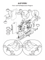
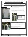
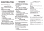
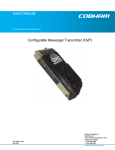
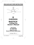
impressions
Only the original
leaves a lasting impression.
Cover and Pad User Manual
Cover and Pad User Manual
Table of Contents
Overview . . . . . . . . . . . . . . . . . . . . . . . . . . . . . . . 1
FAQ’s (frequently asked questions) . . . . . . . . . . 2-3
Body Shirt Pressing Equipment . . . . . . . . . . . . 4-10
Collar & Cuff Presses . . . . . . . . . . . . . . . . . . 11-15
Drycleaning Presses . . . . . . . . . . . . . . . . . . . . 16-20
Cover & Mat Changing Instruction . . . . . . . 21-25
Promotional Flyer. . . . . . . . . . . . . . . . . . . . . . . . . ??
Machine Inventory Report . . . . . . . . . . . . . . . . ??-??
Manual for Quality Improvement . . . . . . . . . . . . ??
Parts Order Form . . . . . . . . . . . . . . . . . . . . . . . . . ??
CN-561
Covers and Pads
Parts Code Chart
and
List Prices
Part
Parts No.
Description
Machine Model No.
No./Unit
List Price
BODY
S0B501
S0B502
S0B503
S0B504
Body Cover
Body Felt Pad 8 mm
Body SH Silicone 10mm
Lower Body Rear Felt Pad
CN561
CN561
CN561
CN561
1
2
1
1
155.00
42.00
388.50
TAIL
S0B514
S0B506
Tail Clamp Cover
Tail Clamp Felt Pad
CN561
CN561
1
1
24.00
TUCK
S0B507
S0B508
S0B509
No. 8 Tuck Cover
No. 8 Tuck Felt Pad 5mm
No. 8 Tuck H Silicone 6mm
CN561
CN561
CN561
2
2
2
12.00
4.00
15.00
NECK
S0B023
S0B024
Neck Clamp(Small) Cover
Neck Clamp(Small) Orange Silicone
VARIOUS MODELS
VARIOUS MODELS
1
1
4.50
4.00
SHORT SLEEVE
S0B017
S0B031
Short Sleeve Cover
Short Sleeve Holder Cover
VARIOUS MODELS
VARIOUS MODELS
2
2
12.00
12.00
CUFF
S0B025
No. 1 Cuff Clamp Cover
VARIOUS MODELS
4
9.00
Sankosha USA, Inc.
1901 Landmeier Road • Elk Grove Village, IL 60007
Toll-Free (888) 427-9120 • Fax (847) 427-9634
www.sankosha-inc.com
[email protected]
CN-561
Cover and Pad Replacement Diagram
S0B506
S0B505
S0B501
S0B031
S0B017
S0B024
S0B023
S0B504
S0B502
S0B503
S0B507
S0B508
Left Side
Right Side
S0B025
S0B509
CN-565
Covers and Pads
Parts Code Chart
and
List Prices
Part
Parts No.
Description
Machine Model No.
BODY
S0B511
S0B512
S0B513
Body Cover
Body Felt Pad 8 mm
Body SH Silicone 10mm
CN565
CN/565/566/567/CF160/161
CN/565/566/567/CF160/161
1
2
1
155.00
42.00
388.50
TAIL
S0B514
Tail Clamp Cover
CN/565/566/567/CF161
1
24.00
TUCK
S0B515
S0B516
S0B517
S0B518
No.
No.
No.
No.
CN/565/566/567/ALP550
CN/565/566/567/ALP550
CN/565/566/567/ALP550
CN/565/566/567/ALP550
1
1
2
2
13.50
13.50
4.00
15.00
NECK
S0B023
S0B024
Neck Clamp(Small) Cover
Neck Clamp(Small) Orange Silicone
VARIOUS MODELS
VARIOUS MODELS
1
1
4.50
4.00
SHORT SLEEVE
S0B017
S0B031
Short Sleeve Cover
Short Sleeve Holder Cover
VARIOUS MODELS
VARIOUS MODELS
2
2
12.00
12.00
CUFF
S0B025
Cuff Clamp Cover
VARIOUS MODELS
4
9.00
Sankosha USA, Inc.
10
10
10
10
Tuck
Tuck
Tuck
Tuck
Cover (Right)
Cover (Left)
Felt Pad 5mm
H Silicone 6mm
1901 Landmeier Road • Elk Grove Village, IL 60007
Toll-Free (888) 427-9120 • Fax (847) 427-9634
No./Unit
List Price
www.sankosha-inc.com
[email protected]
Missing Diagram
CN-566
Covers and Pads
Parts Code Chart
and
List Prices
Part
Parts No.
Description
Machine Model No.
No./Unit
List Price
BODY
S0B519
S0B512
S0B513
Body Cover
Body Felt Pad 8 mm
Body SH Silicone 10mm
CN566
CN565/566/567/CF160/161
CN565/566/567/CF160/161
1
2
1
159.00
42.00
388.50
TAIL
S0B514
Tail Clamp Cover
CN565/566/567/CF161
1
24.00
TUCK
S0B515
S0B516
S0B517
S0B518
No.
No.
No.
No.
CN565/566/567/ALP550
CN565/566/567/ALP550
CN565/566/567/ALP550
CN565/566/567/ALP550
1
1
2
2
13.50
13.50
4.00
15.00
NECK
S0B023
S0B024
Neck Clamp (Small) Cover
VARIOUS MODELS
Neck Clamp (Small) Orange Silicone VARIOUS MODELS
1
1
4.50
4.00
SHORT SLEEVE
S0B017
S0B031
Short Sleeve Cover
Short Sleeve Holder Cover
VARIOUS MODELS
VARIOUS MODELS
2
2
12.00
12.00
CUFF
S0B025
No. 1 Cuff Clamp Cover
VARIOUS MODELS
4
9.00
Sankosha USA, Inc.
10
10
10
10
Tuck
Tuck
Tuck
Tuck
Cover (Right)
Cover (Left)
Felt Pad 5mm
Felt Silicone 6mm
1901 Landmeier Road • Elk Grove Village, IL 60007
Toll-Free (888) 427-9120 • Fax (847) 427-9634
www.sankosha-inc.com
[email protected]
Missing Diagram
CN-567
Covers and Pads
Parts Code Chart
and
List Prices
Part
Parts No.
Description
Machine Model No.
No./Unit
List Price
BODY
S0B520
S0B512
S0B521
S0B513
Body
Body
Body
Body
CN567
CN565/566/567/CF160/161
CN567/CF161
CN565/566/567/CF160/161
1
1
1
1
159.00
42.00
65.00
388.50
TAIL
S0B514
Tail Clamp Cover
CN565/566/567/CF161
1
24.00
TUCK
S0B515
S0B516
S0B517
S0B518
No.
No.
No.
No.
CN565/566/567/ALP550
CN565/566/567/ALP550
CN565/566/567/ALP550
CN565/566/567/ALP550
1
1
2
2
13.50
13.50
4.00
15.00
NECK
S0B023
S0B024
Neck Clamp (Small) Cover
VARIOUS MODELS
Neck Clamp (Small) Orange Silicone VARIOUS MODELS
1
1
4.50
4.00
SHORT SLEEVE
S0B017
S0B031
Short Sleeve Cover
Short Sleeve Holder Cover
VARIOUS MODELS
VARIOUS MODELS
2
2
12.00
12.00
CUFF
S0B050
No. 2 Cuff Clamp Cover
(Left/Lower Right/Upper)
CN567/CF161/ALP550
2
9.00
No. 2 Cuff Clamp Cover
(Left/Upper Right/Lower)
CN567/CF161/ALP550
2
9.00
S0B051
Sankosha USA, Inc.
Cover
Felt Pad 8 mm
Felt Pad 12mm
SH Silicone 10mm
10
10
10
10
Tuck
Tuck
Tuck
Tuck
Cover (Right)
Cover (Left)
Felt Pad 5mm
Felt Silicone 6mm
1901 Landmeier Road • Elk Grove Village, IL 60007
Toll-Free (888) 427-9120 • Fax (847) 427-9634
www.sankosha-inc.com
[email protected]
Missing Diagram
LP-570U
Covers and Pads
Parts Code Chart
and
List Prices
Part
Parts No.
Description
Machine Model No.
No./Unit
List Price
BODY
S0B600
S0B601
S0B602
S0B603
Body
Body
Body
Body
LP570/170/175/ALP550
LP570/170/175/ALP550
LP570/170/175/185/ALP550
LP570/170/175/ALP550
1
1
1
1
159.00
65.00
60.50
388.50
TAIL
S0B604
Tail Clamp Cover
LP570/170/175/ALP550
1
24.00
FRONT TUCK
S0B106
S0B107
S0B108
S0B109
Front
Front
Front
Front
Tuck
Tuck
Tuck
Tuck
Cover
Felt Pad (Left) 5mm
Felt Pad (Right) 5mm
H Silicone 6mm
LP570/170/175
LP570/170/175
LP570/170/175
LP570/170/175
2
1
1
2
10.50
4.00
4.00
10.50
REAR TUCK
S0B110
S0B111
S0B112
S0B113
S0B114
Rear
Rear
Rear
Rear
Rear
Tuck
Tuck
Tuck
Tuck
Tuck
Cover (Left)
Felt Pad (Left) 5 mm
Cover (Right)
Felt Pad (Right) 5 mm
SH Silicone 10mm
LP570/170/175
LP570/170/175
LP570/170/175
LP570/170/175
LP570/170/175
1
1
1
1
2
9.00
4.00
9.00
4.00
18.00
NECK
S0B023
S0B024
Neck Clamp (Small) Cover
VARIOUS MODELS
Neck Clamp (Small) Orange Silicone VARIOUS MODELS
1
1
4.50
4.00
SHORT SLEEVE
S0B017
S0B031
Short Sleeve Cover
Short Sleeve Holder Cover
VARIOUS MODELS
VARIOUS MODELS
2
2
12.00
12.00
CUFF
S0B115
Cuff Clamp Cover
LP570/170/175
2
9.00
Sankosha USA, Inc.
Cover
Felt Pad (Upper) 12mm
Felt Pad (Lower) 8 mm
SH Silicone 10mm
1901 Landmeier Road • Elk Grove Village, IL 60007
Toll-Free (888) 427-9120 • Fax (847) 427-9634
www.sankosha-inc.com
[email protected]
LP-570U
Cover and Pad Replacement Diagram
ALP-550U
Covers and Pads
Parts Code Chart
and
List Prices
Part
Parts No.
Description
Machine Model No.
No./Unit
List Price
BODY
S0B600
S0B601
S0B602
S0B603
Body
Body
Body
Body
LP570/170/175/ALP550
LP570/170/175/ALP550
LP570/170/175/185/ALP550
LP570/170/175/ALP550
1
1
1
1
159.00
65.00
60.50
388.50
TAIL
S0B604
Tail Clamp Cover
LP570/170/175/ALP550
1
24.00
TUCK
S0B515
S0B516
S0B517
S0B518
No.10
No.10
No.10
No.10
CN565/566/567/ALP550
CN565/566/567/ALP550
CN565/566/567/ALP550
CN565/566/567/ALP550
1
1
2
2
13.50
13.50
4.00
15.00
NECK
S0B023
S0B024
Neck Clamp(Small) Cover
Neck Clamp(Small) Orange Silicone
VARIOUS MODELS
VARIOUS MODELS
1
1
4.50
4.00
SHORT SLEEVE
S0B017
S0B031
Short Sleeve Cover
Short Sleeve Holder Cover
VARIOUS MODELS
VARIOUS MODELS
2
2
12.00
12.00
CUFF
S0B050
No.2 Cuff Clamp Cover
(Left/Lower Right/Upper)
No.2 Cuff Clamp Cover
(Left/Upper Right/Lower)
CN557/567/161/ALP550
2
9.00
CN557/567/161/ALP550
2
9.00
S0B051
Sankosha USA, Inc.
Cover
Felt Pad (Upper) 12mm
Felt Pad (Lower) 8 mm
SH Silicone 10mm
Tuck
Tuck
Tuck
Tuck
Cover(Right)
Cover(Left)
Felt Pad 5mm
H Silicone 6mm
1901 Landmeier Road • Elk Grove Village, IL 60007
Toll-Free (888) 427-9120 • Fax (847) 427-9634
www.sankosha-inc.com
[email protected]
ALP-550U
Cover and Pad Replacement Diagram
S0B600
S0B031
S0B017
100S
S0B024
S0B023
S0B604
ACC-012
S0B601
S0B602
S0B603
S0B516
S0B515
S0B517
S0B051
S0B518
S0B050
Left Side
S0B517
S0B050
S0B518
S0B051
Right Side
CF-150
Covers and Pads
Parts Code Chart
and
List Prices
Part
Parts No.
Description
Machine Model No.
No./Unit
List Price
BODY
S0B522
S0B523
S0B524
S0B525
Apron Cover
Body Felt Pad 8mm
Body Cover(Inner)
Body Felt Pad 4mm
CF150
CF150
CF150
CF150
2
2
2
2
104.95
69.50
82.00
39.95
TUCK
S0B507
S0B508
S0B509
No. 8 Tuck Cover
No. 8 Tuck Felt Pad 5mm
No. 8 Tuck H Silicone 6mm
CN561
CN561
CN561
4
4
4
12.00
4.00
15.00
NECK
S0B015
S0B016
Neck Clamp(Large) Cover
Neck Clamp(Large) Orange Silicone
VARIOUS MODELS
VARIOUS MODELS
2
2
5.00
4.50
BALLOON
S0B526
Balloon Cover
CF150
4
44.50
VACUUM
S0B527
Vacuum Cover
CF150
2
52.50
Sankosha USA, Inc.
1901 Landmeier Road • Elk Grove Village, IL 60007
Toll-Free (888) 427-9120 • Fax (847) 427-9634
www.sankosha-inc.com
[email protected]
Missing Diagram
CF-160
Covers and Pads
Parts Code Chart
and
List Prices
Part
Parts No.
Description
Machine Model No.
No./Unit
List Price
BODY
S0B550
S0B512
S0B513
Body Cover
Body Felt Pad 8 mm
Body SH Silicone 10mm
CF160
CN565/566/567/CF160/161
CN565/566/567/CF160/161
2
4
2
155.00
42.00
388.50
TAIL
S0B551
Tail Clamp Cover
CF160
2
24.00
TUCK
S0B552
S0B553
S0B554
S0B555
S0B556
S0B557
No.
No.
No.
No.
No.
No.
CF160/161
CF160/161
CF160/161
CF160/161
CF160/161
CF160/161
2
2
2
2
2
2
13.50
13.50
4.00
4.00
15.00
15.00
NECK
S0B023
S0B024
Neck Clamp(Small) Cover
Neck Clamp(Small) Orange Silicone
VARIOUS MODELS
VARIOUS MODELS
2
2
4.50
4.00
SHORT SLEEVE
S0B017
S0B031
Short Sleeve Cover
Short Sleeve Holder Cover
VARIOUS MODELS
VARIOUS MODELS
4
4
12.00
12.00
CUFF
S0B025
No.1 Cuff Clamp Cover
VARIOUS MODELS
8
9.00
BLOWER
S0B068
Blower Cover
CF160
1
15.00
Sankosha USA, Inc.
12
12
12
12
12
12
Tuck
Tuck
Tuck
Tuck
Tuck
Tuck
Cover(Right)
Cover(Left)
Felt Pad 5mm(Right)
Felt Silicone 5mm(Left)
H Silicone 6mm(Right)
H Silicone 6mm(Left)
1901 Landmeier Road • Elk Grove Village, IL 60007
Toll-Free (888) 427-9120 • Fax (847) 427-9634
www.sankosha-inc.com
[email protected]
Missing Diagram
CF-161U
Covers and Pads
Parts Code Chart
and
List Prices
Part
Parts No.
Description
Machine Model No.
No./Unit
List Price
BODY
S0B558
S0B512
S0B521
S0B513
Body
Body
Body
Body
CF161
CN565/566/567/CF160/161
CN565/566/567/CF161
CN565/566/567/CF160/161
2
2
2
2
159.00
42.00
65.00
388.50
TAIL
S0B514
Tail Clamp Cover
CN565/566/567/CF161
2
24.00
TUCK
S0B552
S0B553
S0B554
S0B555
S0B556
S0B557
No.
No.
No.
No.
No.
No.
CF160/161
CF160/161
CF160/161
CF160/161
CF160/161
CF160/161
2
2
2
2
2
2
13.50
13.50
4.00
4.00
15.00
15.00
NECK
S0B023
S0B024
Neck Clamp(Small) Cover
Neck Clamp(Small) Orange Silicone
VARIOUS MODELS
VARIOUS MODELS
2
2
4.50
4.00
SHORT SLEEVE
S0B017
S0B031
Short Sleeve Cover
Short Sleeve Holder Cover
VARIOUS MODELS
VARIOUS MODELS
4
4
12.00
12.00
CUFF
S0B050
No. 2 Cuff Clamp Cover
(Left/Lower Right/Upper)
No. 2 Cuff Clamp Cover
(Left/Upper Right/Lower)
CN567/CF161/ALP550
4
9.00
CN567/CF161/ALP550
4
9.00
CF161/170/175
1
15.00
S0B051
BLOWER
S0B081
Cover
Felt Pad 8 mm
Felt Pad 12mm
SH Silicone 10mm
12
12
12
12
12
12
Tuck
Tuck
Tuck
Tuck
Tuck
Tuck
Cover(Right)
Cover(Left)
Felt Pad 5mm(Right)
Felt Silicone 5mm(Left)
H Silicone 6mm(Right)
H Silicone 6mm(Left)
Blower Cover
Sankosha USA, Inc.
1901 Landmeier Road • Elk Grove Village, IL 60007
Toll-Free (888) 427-9120 • Fax (847) 427-9634
www.sankosha-inc.com
[email protected]
CF-161U
Cover and Pad Replacement Diagram
S0B031
S0B017
S0B023
S0B024
S0B557
S0B556
S0B555
S0B051
S0B081
S0B554
S0B553
S0B050
S0B552
S0B514
S0B521
S0B558
S0B513
S0B512
LP-170U
Covers and Pads
Parts Code Chart
and
List Prices
Part
Parts No.
Description
Machine Model No.
No./Unit
List Price
BODY
S0B600
S0B601
S0B602
S0B603
Body
Body
Body
Body
LP570/170/175/ALP550
LP570/170/175/ALP550
LP570/170/175/185/ALP550
LP570/170/175/ALP550
2
2
2
2
159.00
65.00
60.50
388.50
TAIL
S0B604
Tail Clamp Cover
LP570/170/175/ALP550
2
24.00
FRONT TUCK
S0B106
S0B107
S0B108
S0B109
Front
Front
Front
Front
Tuck
Tuck
Tuck
Tuck
Cover
Felt Pad (Left) 5mm
Felt Pad (Right) 5mm
H Silicone 6mm
LP570/170/175
LP570/170/175
LP570/175
LP570/175
4
2
2
4
10.50
4.00
4.00
10.50
REAR TUCK
S0B110
S0B111
S0B112
S0B113
S0B114
Rear
Rear
Rear
Rear
Rear
Tuck
Tuck
Tuck
Tuck
Tuck
Cover (Left)
Felt Pad (Left) 5 mm
Cover (Right)
Felt Pad (Right) 5 mm
SH Silicone 10mm
LP570/175
LP570/175
LP570/175
LP570/175
LP570/175
2
2
2
2
4
9.00
4.00
9.00
4.00
18.00
CUFF
S0B115
Cuff Clamp Cover
LP570/175
4
9.00
NECK
S0B023
S0B024
Neck Clamp (Small) Cover
VARIOUS MODELS
Neck Clamp (Small) Orange Silicone VARIOUS MODELS
2
2
4.50
4.00
SHORT SLEEVE
S0B017
S0B031
Short Sleeve Cover
Short Sleeve Holder Cover
VARIOUS MODELS
VARIOUS MODELS
4
4
12.00
12.00
BLOWER
S0B081
Blower Cover
CF161/170/175
1
15.00
Sankosha USA, Inc.
Cover
Felt Pad (Upper) 12mm
Felt Pad (Lower) 8 mm
SH Silicone 10mm
1901 Landmeier Road • Elk Grove Village, IL 60007
Toll-Free (888) 427-9120 • Fax (847) 427-9634
www.sankosha-inc.com
[email protected]
LP-170U
Cover and Pad Replacement Diagram
S0B600
S0B031
S0B017
S0B024
S0B023
S0B604
S0B601
S0B602
S0B115
S0B603
S0B012
S0B081
S0B116
Left Side
Right Side
S0B112
S0B110
S0B113
S0B111
S0B106
S0B114
S0B114
S0B106
S0B107
S0B109
S0B108
S0B109
LP-175U
& LP-185U
Covers and Pads
Parts Code Chart
and
List Prices
LP-175U
LP-185U
Part
Parts No.
Description
Machine Model No.
No./Unit
List Price
BODY
S0B600
S0B601
S0B602
S0B603
Body
Body
Body
Body
LP570/170/175/185/ALP550
LP570/170/175/185/ALP550
LP570/170/175/185/ALP550
LP570/170/175/185/ALP550
2
2
2
2
159.00
65.00
60.50
388.50
TAIL
S0B604
Tail Clamp Cover
LP570/170/175/185/ALP550
2
24.00
FRONT TUCK
S0B106
S0B107
S0B108
S0B109
Front
Front
Front
Front
Tuck
Tuck
Tuck
Tuck
Cover
Felt Pad (Left) 5mm
Felt Pad (Right) 5mm
H Silicone 6mm
LP570/175/185
LP570/175/185
LP570/175/185
LP570/175/185
4
2
2
4
10.50
4.00
4.00
10.50
REAR TUCK
S0B110
S0B111
S0B112
S0B113
S0B114
Rear
Rear
Rear
Rear
Rear
Tuck
Tuck
Tuck
Tuck
Tuck
Cover (Left)
Felt Pad (Left) 5 mm
Cover (Right)
Felt Pad (Right) 5 mm
SH Silicone 10mm
LP570/175/185
LP570/175/185
LP570/175/185
LP570/175/185
LP570/175/185
2
2
2
2
4
9.00
4.00
9.00
4.00
18.00
CUFF
S0B115
Cuff Clamp Cover
LP570/175/185
4
9.00
NECK
S0B023
S0B024
Neck Clamp(Small) Cover
Neck Clamp(Small) Orange Silicone
VARIOUS MODELS
VARIOUS MODELS
2
2
4.50
4.00
SHORT SLEEVE
S0B605
S0B606
S0B607
S0B608
Short
Short
Short
Short
LP175/185
LP175/185
LP175/185
LP175/185
1
1
1
1
12.00
12.00
BLOWER
S0B081
Blower Cover
CF161/170/175/185
1
15.00
Sankosha USA, Inc.
Cover
Felt Pad (Upper) 12mm
Felt Pad (Lower) 8 mm
SH Silicone 10mm
Sleeve
Sleeve
Sleeve
Sleeve
Cover(Left)
Cover(Right)
Holder Cover(Left)
Holder Cover(Right)
1901 Landmeier Road • Elk Grove Village, IL 60007
Toll-Free (888) 427-9120 • Fax (847) 427-9634
www.sankosha-inc.com
[email protected]
LP-175U & LP-185U
Cover and Pad Replacement Diagram
S0B607
S0B600
S0B608
100S
S0B604
S0B605
Left Side
S0B606
100S
Right Side
S0B601
S0B024
S0B602
S0B603
S0B023
S0B081
CSP-UNT-001
S0B116
S0B115
Left Side
Right Side
S0B112
S0B110
S0B113
S0B111
S0B114
S0B106
S0B114
S0B107
S0B106
S0B109
S0B108
S0B109
Body cover changing instruction (1/3)
1・How to remove old body cover
Please let the machine cool down completely before changing the cover.
Caution
There is risk
of being burnt if this is not done. Please power off the power for all operations.
●Procedure for removing body cover.
Body cover front
Remove in following order from ①.
・Numbers in picture refer to order in which either cover
※
⑧
⑨
or parts should be removed.
⑧
⑨
・Red numbers=Front side
Black numbers=Rear side
①Remove duct from machine.
②Remove the string of hem.
⑩
Refer to rear side, process ③∼⑥.
⑦
⑦
⑦Remove spring hook of stainless rod. (Both side shoulders)
⑦
①Duct
②
⑧Undo strings of both shoulders.
⑨Pull out stainless rod from both side shoulders.(Front×2 Rear×2 Total 4)
⑨
*Front side stainless rod is long.
※Removed stainless rod is to reused
in new cover.
⑩Raise ※neck clamp and remove body cover from machine.
Tail clamp over and Tail receiver cover
Machine rear side cover removal process
③Unfasten velcro (L type ) of tail receiver cover.
④Remove fastener and separate.
⑤Undo string of tail receiver cover and remove cover.
⑥Undo the string of tail clamp cover.
⑤
⑥
④
⑤Close-up picture
※Once fastener is removed strings will
③
Number
Date
be visible.
SP-LP-BC-UE-1
May,2009.
REV
2
Adaptive machine・Lot number
Designed
LP-570/170/V2/175/185/ALP-550
Furuya
S A N K O S H A
Body cover changing instruction (2/3)
2・How to install new tail clamp cover and tail receiver cover.
※All photos are LP-570.
Most machines are of different compositions but installation of cover is basically the same.
●Procedure for tail clamp cover and tail receiver cover.
Equipped Tail clamp cover
Install in following order from ①.
and Tail receiver cover
① Pass the bands of tail clamp cover over tail clamp plate
and fit inside upper part onto hook.
①
④
①
③
①
② Pass bottom of tail receiver cover (L type velcro parts)
②
as seen in photos and fasten in place with velcro.
②
Position of L type velcro.
※photo ② refers to upper
left side.
③Place tail receiver cover and tie-up string.
③
③
④Place upper tail clamp cover over hook as seen in photo.
④
Number
Date
④
SP-LP-BC-UE-1
May,2009.
REV
2
Adaptive machine・Lot number
Designed
LP-570/170/V2/175/185/ALP-550
Furuya
S A N K O S H A
Body cover changing instruction(3/3)
3・How to install new body cover
●Procedure for body cover attachment.
Install in following order from ①.
Completion of body cover install.
①Raise ※neck clamp and place on cover.
※
①
②
⑦
②Insert stainless rods in front and back bodice from left shoulder.
②
⑦
* Front side is long.
①
③
③
②
③
⑧
⑧
(M)
(M)
⑥
(M)
⑤
⑨
⑥
③Place body cover sides starting with sides of side expander and fasten velcro.
⑤ (M)
④
⑩ ⑪
(*)See (M) in photo.
④Pass cover over duct as seen in photo and fasten velcro.
④
(*) Pull inside string to front
Velcro position
as seen in photo, in front of duct.
※ All photos are LP-570 model. In case of
LP-170・V2・175 model cover should equally
Velcro position
spread over duct both left and right④.
⑤⑥Put hem cloth (right and left) of front rear hem on end of body.
⑤
⑪Fix hem string over hook of machine together with cloth.
⑥
⑪
⑪
後押え
Tail clamp
⑦Pull in and tie-up string of right and left shoulders.
⑧Spring hook should then be hooked over stainless rod.
(*) Refer to photo ⑦for how to remove body cover.
⑨Close fastener and fasten bottom velcro.
⑨
⑫Connect duct hose.
⑫
⑩
⑬Flatten out any wrinkles in body cover by hand.
Machine hook
⑩Pass the hem string to loop of tail receiver cover.
Number
Date
SP-LP-BC-UE-1
May,2009.
REV
2
Adaptive machine・Lot number
Designed
LP-570/170/V2/175/185/ALP-550
Furuya
S A N K O S H A
Body felt pad changing instruction (1/1)
1・How to remove old body felt pads and body silicon.
Caution
Please let the machine cool down completely before changing the cover.
There is risk
of being burnt if this is not done. Please power off the power for all operations.
●Procedure for removing body felt pads and body silicon.
Body felt pads front
Remove in following order from ①.
・Numbers in picture refer to order in which either cover
※
or parts should be removed.
①Raise ※neck clamp and remove body felt pads 12mm, 8mm
and silicon 10mm.
Order (Photo : From left side)
①body silicon 10mm
①
②
②body felt pad 8mm
③body felt pad 12mm
③
Body silicon and body felt pads left side
Caution : How to install body silicon and body felt pads.
※Put body silicon and body felt pads equally on left and right sides.
(Refers to upper left side photo.)
※Unite line of machine and line of the shoulders.
(Refers to bottom left side photo.)
①②③
Number
Date
SP-LP-BP-UE-1
May,2009.
REV
2
Adaptive machine・Lot number
Designed
LP-570/170/V2/175/185/ALP-550
Furuya
S A N K O S H A
Body cover changing instruction (1/3)
1・Installation of used body cover
Please let the machine cool down completely before changing the cover.
Caution
There is risk of
being burnt if this caution is not respected. Please turn off the power for all operations.
●How to remove body cover.
Front of body cover
Remove the body cover in following order.
・Number of the picture means the removal order and position.
・Red numbers=Front side
※
⑧
⑧
Black numbers=Rear side
①Remove duct hose from the machine.
②Loosen lower side string.
Regarding to procedure③∼⑥, refer to How to remove tail cover’.
⑨
⑦
⑦Remove the edge of the cover from both side hooks.
⑦
⑦
(M)
(M)
①
②
Side hook position in rear side
Velcro position
(There are 2hooks in each front side and 1hook in each rear side.)
Refer to the left picture⑦ for the hook position.
⑧Loosen strings of both shoulder positions.
⑨Raise neck clamp(※) and remove body cover from the machine.
Tail receiver cover and tail clamp cover
How to remove tail cover
③Unfasten velcro (L form ) of tail receiver cover.
④Unfasten zipper and separate side expander cover from
tail receiver cover.
⑤Loosen string of tail receiver cover and remove the cover.
⑥
⑥Loosen string of tail clamp cover and remove the cover.
⑤
④
Detail of ⑤
※Inside of the zipper, there are strings.
③
Number
Date
SP-CF-BC-UE-1
Nov, 2009
REV
1
Adaptive machine・Lot number
Designed
CF-160
SP.Dep
S A N K O S H A
Collar cover・felt・silicon changing instruction
Please let the machine cool down completely before changing the cover.
Caution
There is risk of being burnt if this is not done. Please power off the power for all operations.
① Remove the middle press cover (Black) of front side.
Collar cover
Middle press
(LP690:2 screws LP690-V2/LP695:4 screws)
cover (Black)
② Remove the spring hook (4 places) which has fixed the cover and
remove the collar cover.
*Have the ring of spring hook and remove it.
③ Install cover ⇒felt (white) ⇒silicon (yellow) to new collar cover.
Remove the stainless rods from old cover and install them.
④ Place a cover so that a name tag appears in front. Hook the spring hook
Screw×2(Front side)
(4places) on the stainless rods and fix the cover.
LP690・LP690-V2・LP695
⑤ Install the middle press cover (Black).
Insert the felt (white)
to cloth of both sides.
Silicon is installed so that
an unevenness side may be in sight.
Screw×2(Right and left)
Only LP690-V2・LP695
Insert stainless rods
(2 places) from this hole.
① Remove the middle press cover
Model
Stainless rods
③
Set preparations of the collar cover
Set name tag
to the front.
Has this
Spring hook
Front and rear Total 4
Hook the stainless rods
Front and rear(2 places)
Caution:
④
Edge is sharp!!
②Remove the collar cover
Number
Date
⑤
SP-LP-CC-UE-1
Sept,2009.
REV
1
Right and left(2 places)
Set the collar cover
Install the middle press cover (Black)
Adaptive machine・Lot number
Designed
LP-690/V2/695
Furuya
S A N K O S H A
Body cover changing instruction (2/3)
2・Installation of new tail clamp cover and tail receiver cover.
●How to install tail clamp cover and tail receiver cover.
Install tail covers in following order.
Installed tail receiver cover and tail clamp cover
① Put on tail receiver cover to tail receiver cover plate and
tighten strings.
①
①
③
①
② Pass through the tail receiver cover(L form Velcro ) as
picture② and attach them with Velcro.
②
②
L form Velcro
※ Refer to picture②of
‘Installed tail receiver
cover and tail clamp cover’
③ Put on tail clamp cover to tail clamp plate and tighten strings.
③
Number
Date
③
SP-CF-BC-UE-1
Nov, 2009
REV
1
Adaptive machine・Lot number
Designed
CF-160
SP.Dep
S A N K O S H A
Body cover changing instruction(3/3)
3・Installation of new body cover
●How to install body cover.
Installed body cover
Install the body cover in following order.
①Raise neck clamp(※) and put on body cover.
※
①
⑥
②Put on side expander cover to both side expander from top position and
⑥
attach them with Velcro(M).
②
⑦
⑦
⑤
⑤
⑧
②
①
②
⑧
(M) ④
④ (M)
③Pass the cover over the duct and fix it with Velcro .
⑨⑩
③⑪
⑫
③
(*)Pull strings to front so that
Velcro position
only cover pass around the duct.
※It is possible to pass duct through right or left
side ③according to duct direction.
Velcro position
Hook the edge of front④ and rear cover⑤ on body head.
⑩Pass string of lower position under the copper pipe
⑤
④
and pass it through string loop. Then pull it so that
string and cloth are hooked on body head.
⑩
⑩
⑥Tighten strings of both shoulders position.
⑦Hook the edge of the cover on both side hooks.
(*)Refer to procedure⑦ of How to remove old body cover
⑧Attach tail receiver cover and body cover with zipper
and Velcro.
Picture of the body head.
⑨Pass the lower string under the cylinder and pass through
side expander cover from lower position.
⑧
⑨
Top of the string.
⑪Attach strings with Velcro in front position.
⑪
⑫
⑫Install duct hose.
⑬Flatten out wrinkles of body cover by hand.
Number
Date
Adaptive machine・Lot number Designed
SP-CF-BC-UE-1
Nov, 2009
REV
1
CF-160
SP.Dep
S A N K O S H A
Cuffs cover・felt・silicon changing instruction
Please let the machine cool down completely before changing the cover.
Caution
There is risk of being burnt if this is not done. Please power off the power for all operations.
※The indicated procedure and quantity are the things only left cuffs.
①
Remove the cuffs cover
Right cuffs should also change in the same procedure.
※The size of cuffs differs between LP690 and LP690V2/LP695.
① Remove the cuffs cover.
LP690:Nut ×4
(Only in cover exchange, install the cover in the procedure of ⑤.)
LP690V2/LP695:Screw×4
② Loosen the nut screw front and rear cuffs parts (Total 12).Pull the fitting metal
and remove the felt and silicon.
※Nut and screw are exchangeable only by loosening.
③ Set to right and left cuffs in order of a silicon(small)⇒felt(small).
Install the fitting metal and tighten the screw.
Screw×8
※Be careful of direction of felt.(See in photo)
④ Set to center cuffs in order of the silicon(Big)⇒felt(Big).
Install the fitting metal and tighten the screw.
※Be careful of direction of felt.( Front and reverse)See in photo.
⑤ Install the cuffs cover.
※The cover has left and right. Install a name tag and a string
Fitting metal
Big 2 Small 4
Screw and nut are
※ Beige side should
※Pull a string strongly, and attach so that there are no wrinkles.
only loosened.
②
Felt(Big)
outside.
be in sight.
Not unevenness side is top
Remove the felt
Silicon(Small)
Pass hole to nut
※Felt(Big)surround
※Not unevenness
side is top
felt(Small)and install it.
Felt(Small)
※Beige side should be
Fitting metal(Big)
in sight.
④
Install the cuffs (Big)
※ Set the convex
Pass hole to screw
downward.
Name tag
Fitting metal
String
(Small)
(Out side)
(Out side・front)
③
Number
Date
⑤
Install the cuffs (small)
SP-LP-CFC-UE-1
Sept,2009.
REV
1
Install the cuffs cover
Adaptive machine・Lot number
Designed
LP-690/V2/695
Furuya
S A N K O S H A
Collar cover・felt・silicon changing instruction
Caution
Please let the machine cool down completely before changing the cover.
There is risk of being burnt if this is not done. Please power off the power for all operations.
※Move the cover exchange side table to the front.
①
Remove the front guard side (2 screws) and the rear guard side of
table center(2 screws).
※Remove this, when fastened together with the center partition
plate.
② Remove the spring hook (6 places) which has fixed the cover and
remove the collar cover.
Guard front side
③ Install cover ⇒felt (white) ⇒silicon (yellow) to new collar cover.
Screw ×2
Remove the stainless rods from old cover and install them.
④ Place a cover so that a name tag appears in front. Hook the spring hook
Center partition plate
(6places) on the stainless rods and fix the cover.
⑤ Install the front guard side and the rear guard side of table center.
Guard
Insert the felt (white)
to cloth of both sides.
center of the table
Screw ×2
Silicon is installed so that
※Only the side to exchange.
an unevenness side may be in sight.
① Remove the middle press cover
Insert stainless rods
(2 places) from this hole.
Stainless rods
③
Model
Set preparations of the collar cover
Set name tag
to the front.
Has this
Spring hook
×6
Front, rear,right and left
Hook the stainless rods
Caution:
④
Edge is sharp!!
②
Remove the collar cover
Number
Date
⑤
SP-LP-CC-UE-2
Sept,2009.
REV
Right and left(4 places)
Front and rear(2 places)
1
Set the collar cover
Install the front and rear guard.
Adaptive machine・Lot number
Designed
LP-370/V2
Furuya
S A N K O S H A
Cuffs cover・felt・silicon changing instruction
Please let the machine cool down completely before changing the cover.
Caution
There is risk of being burnt if this is not done. Please power off the power for all operations.
※The indicated procedure and quantity are the things only left cuffs.
① Remove the cuffs cover
Right cuffs should also change in the same procedure.
① Remove the cuffs cover.
(Only in cover exchange, install the cover in the procedure of ⑤.)
Nut ×4
② Loosen the nut (×4) screw (×8) front and rear cuffs parts.
Pull the fitting metal and remove the felt and silicon.
※Nut and screw are exchangeable only by loosening.
③ Set to right and left cuffs in order of a silicon(small)⇒felt(small).
Install the fitting metal and tighten the screw.
Screw
※Be careful of direction of felt.(See in photo)
×8
④ Set to center cuffs in order of the silicon(Big)⇒felt(Big).
Install the fitting metal and tighten the screw.
※Be careful of direction of felt.( Front and reverse)See in photo.
⑤ Install the cuffs cover.
※The cover has left and right. Install a name tag and a string
Fitting metal
Big 2
Small 4
outside.
Screw and nut
②
Felt(Big)
※Pull a string strongly, and attach so that there are no wrinkles.
only loosened
※ Beige side should
Remove the felt
Not unevenness side is top
be in sight.
Silicon(Small)
Pass hole to nut
※Felt(Big)surround
felt(Small)and install it.
Felt(Small)
※Beige side should be
Fitting metal(Big)
in sight.
④
※ Set the convex
downward.
Install the cuffs (Big)
Pass hole to screw
Name tag
Fitting metal
String
(Small)
③
Number
Date
(Out side)
(Out side・front)
Install the cuffs (small)
⑤
SP-LP-CFC-UE-2
Sept,2009.
REV
1
Install the cuffs cover
Adaptive machine・Lot number
Designed
LP-370/V2
Furuya
S A N K O S H A
Body cover and Clamp cover changing instruction
Caution
Please let the machine cool down completely before changing the cover.
There is risk of
being burnt if this caution is not respected. Please turn off the power for all operations.
Pass strings through the
hole and tie it inside
Rear
Holes(2 positions)
∼ How to replace body cover∼
1:Remove used body cover.
2:Put on the new body cover.
Pass strings through
3:Tie the strings of rear and front low like
the hole from lower
the picture.
side and tie it inside.
Front low
Tail clamp
Left side vents clamp
Right side vents clamp
Left side vents receiver
Right side vents receiver
Front
※ The body and tail cover are
removed
Side clamp
in
this
picture
Front clamp
intentionally for this document.
∼ How to replace each clamp cover. ∼
1:Remove the used cover.
2:Match four corners of mat with each metal part and put on the cover.
Number
Date
SP-DF-UC-UE-2
Nov. 2009
REV
1
Adaptive machine・Lot number
Designed
DF100-V2
SP.Dep
S A N K O S H A
Lower body cover changing instruction
Caution
Please let the machine cool down completely before changing the cover.
There is risk of
being burnt if this caution is not respected. Please turn off the power for all operations.
1:Move up the body to make the replacement
easier and turn off the power.
1:Move up the body to make the replacement easier and
turn off the power.
※Operation before turning off the power could injure
※1:Pass the strings inside of
the operators.
the side vents receivers.
2:Remove used lower body cover and put on new one.
Check ※1∼3cautions before the replacement.
※2:Name tag position is
3: Match 4 corners of lower clamp covers with metal
inside of right side .
parts of the lower receivers and tie strings inside.
4: Pass string of lower cover under hooks (8 positions)
and tie it on right side. Then attach covers with
Velcro.
① ①Pass the string of lower cover ② Attach covers with
under hooks (8 positions)
Velcro. (2 positions)
※ The body is removed in this picture
intentionally for this document
※3:Pass the left side
string inside of the
side clamp receiver.
From upper view
③ Tie string not to leak the blower.
2:Put on the lower covers
4:Tie lower body cover string.
Match
4
corners
of
lower
receiver covers with metal parts
of the lower receivers and tie
strings inside.
※Put on other covers on same
way .
4positions(front, rear and two sides)
From upper view
3:Put on lower receiver covers.
Number
Date
SP-DF-LC-UE-1
Nov. 2009
REV
1
Adaptive machine・Lot number
Designed
DF100-V2
SP.Dep
S A N K O S H A
Body cover, felt pad changing instruction
Caution
Please let the machine cool down completely before changing the cover. There is risk of being
burnt if this caution is not respected. Please turn off the power for all operations.
1:Press ‘Tail Clamp Up button’ to remove bolts of tail position
easily. Tail Clamp will move up.
2:Turn off the power.
3:Remove the nuts of front, rear lower plate (6pcs) and spring
hooks (DF550:6 pieces, KF550:8pcs).
Press ‘Tail Clamp up button’.
Then remove body cover and felt pad.
※At same time, remove stainless steel rods(4pcs).
※Be careful not to be injured by the edge of spring hook.
4:Put new body felt pad on the body and pass the bolts of the
1:Tail clamp up
2:Turn off the power
Fixation plate
and fix them with spring hooks.
6:Put new body cover on the body.(Refer to the picture)
7:Install fixation plate with nuts.(Don’t tighten them fully yet)
※Check if the direction of installed plate is correct referring
Nut
(6pcs)
Knot
body (6pcs) through the holes of body felt pad.
(Refer to the picture)
5:Pass stainless steel rods through the side of body felt pad
3:Remove body cover and felt pad.
to the picture.
※Pass strings under the fixation plate.
8:Tie the strings tightly and tighten the nuts fully.
※ At this time, fix them and make bolts flat with the
surface of nuts.
Pass behind the tail clamp
Behind the tail receiver
Inside of side expander
Pass bolts of body through
the holes of felt pad.
4:Install body felt pad
Pass bolts of body through
Spring hook (Inside of the body)
DF550:6pcs
KF550:8pcs
Inside of the lever
the holes of felt pad.
6:Install body cover
Fixing direction
of fixation plate.
Pass the string under fixation plate.
Hold here.
7:Fix fixation plate(not fully)
Attention
Edge is sharp.
Stainless steel rods (4pcs)
※Fix bolts and made them flat with the surface of nuts.
(To protect nut from the damage.)
8:Tie the strings and tighten the nuts
5:Install stainless steel rods and spring hooks.
Number
Date
SP-DF-BC-UE-1
Nov, 2009
REV
1
Adaptive machine・Lot number
Designed
DF550/KF550
SP.Dep
S A N K O S H A
Sankosha U.S.A., Inc.
1901 Landmeier
Elk Grove Village IL 60007-6452
Tel: (847) 427-9120 Fax: (847) 427-9634
www.sankosha-inc.com
Parts Purchase Order Form
Order Date: _____________
SUI Representative Signature____________
Ship to:
Customer:
__________________________
Bill to:
____________________________
Address:
__________________________
____________________________
__________________________
____________________________
__________________________
Phone, Fax, E-mail, other
____________________________
Attn/Tel:
Type:
Send : Ground, Overnight,
2nd Day, US Mail, Pick-Up, Delivery,
PO #: ____________ COD _______Credit Card #__________________________
Exp. Date ___/___
Model #
New Expanders?
Description
S/N
Y/N
HQ Part
Y/N
Part Number
Qty
Charge
Y/N
Back
Order