1
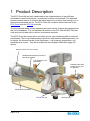
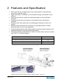
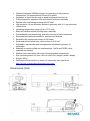
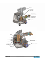
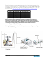
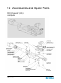
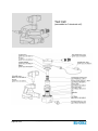
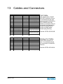
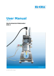
Electrochemical Test Cell ECC-Press-Air (-DL) User Manual © 2012 - 2015 EL-CELL GmbH Release: 1.4 2015-02-11 PCB: ECC-PRESS-DL 1.2 The information in this manual has been carefully checked and believed to be accurate; however, no responsibility is assumed for inaccuracies. EL-CELL GmbH maintains the right to make changes without further notice to products described in this manual to improve reliability, function, or design. EL-CELL GmbH does not assume any liability arising from the use or application of this product. Content 1 Product Description ........................................................................ 3 2 Features and Specification ............................................................. 3 3 Safety Precautions ......................................................................... 7 4 Unpacking ...................................................................................... 7 5 Cell Assembly ................................................................................ 8 6 Operation Modes / Gas Supply .................................................... 11 7 Electrical Connection ................................................................... 11 8 Sample Valve with Septum Port ................................................... 13 9 Software Installation (DL option) .................................................. 14 10 Recording the Pressure Signal with an External Potentiostat ....... 14 11 Disassembly and Cleaning ........................................................... 16 12 Accessories and Spare Parts ....................................................... 17 13 Cables and Connectors................................................................ 18 14 Technical Support ....................................................................... 22 15 Warranty ..................................................................................... 23 EL-CELL GmbH Tempowerkring 8 D-21079 Hamburg - Germany phone:+49 (0)40 790 12 734 fax: +49 (0)40 790 12 736 [email protected] www.el-cell.com Page 2 of 23 ECC_PRESS_AIR_manual / 11.02.2015 1 Product Description The ECC-Press-Air test cell is dedicated to the characterization of gas diffusion electrodes in aprotic electrolytes, in particular for lithium-air batteries. The attached pressure sensor serves to monitor the inside pressure in either a flow-through or in a dead-end pressurized set-up. The ECC-Press-Air combines all the features of the ECC-Press and the ECC-Air test cells. The provided low-dead-volume sampling port/valve serves to draw gas samples from the cell’s headspace. The cell hardware is based on the ECC-Std and ECC-Ref test cells and can be used with or without a reference electrode. The ECC-Press-Air comes with a controller box for easy interfacing with an external potentiostat. The box provides analog outputs for both pressure and temperature. As an option, all relevant signals of the experiment – cell pressure, temperature, cell potentials and current – may be recorded with an integrated USB data logger (DL option). Pressure sensor 0 to 2.5 bar abs. Variable dead volume by means of two sensor spacers Port (plugged or for gas outlet) Sampling valve with syringe port or port for gas inlet Stand (wall mountable) ECC-Air test cell Page 3 of 23 ECC_PRESS_AIR_manual / 11.02.2015 Reference pin 2 Features and Specification ECC-Press-Air test cell dedicated to the characterization of gas-diffusion electrodes in aprotic media Upper electrode is contacted by, and breathes through a perforated current collector Gas inlet and outlet for supply of pressurized gases to the gas diffusion electrode A siphon directs the incoming gas to the backside of the gas diffusion electrode Sampling valve with septum port for drawing gas samples by means of a syringe Attached pressure sensor for monitoring of inside gas pressure. Default pressure range of 0 to 2.5 bar (absolute). Conditioning electronics with analog outputs for pressure and temperature for seamless integration with external instrumentation Total dead volume variable between 4.448 cm3 (both sensor spacers in place) and 16.917 cm3 (without spacer) Dead volume in cm3 Only 1. Both spacers installed* 2. Only ECC1-00-0136-A (sensor spacer B) installed** 3. Only ECC1-00-0135-A (sensor spacer A) installed** 4. No spacer installed** 4.448 10.582 10.783 16.917 * delivery condition **Requires de-mounting of the sensor and must be done at factory. 3 Visualised dead volume (both spacers installed = delivery condition = 3.024 cm ) Page 4 of 23 ECC_PRESS_AIR_manual / 11.02.2015 Optional integrated USB data logger for recording of cell pressure, temperature, cell potentials and current (DL option) Operation in either flow-through or dead-end pressurized set-up Fully equipped for operation with and without reference electrode Reliable ultra-low leakage sealing with PE seal High precision 18 mm diameter sandwich geometry with <0.1 mm electrode concentricity Operating temperature range -20 to +70°C (cell) Easy and reliable electrolyte filling upon assembly Fast assembly and dismantling, and easy cleaning of cell components Electrodes are easily accessible for post-mortem analysis Reusable cell components except for PE seals Small and defined electrolyte volume down to 0.05 cm3 Adjustable, reproducible and homogeneous mechanical pressure on electrodes Materials in media contact are stainless steel 1.4404 and PEEK (other materials on request) Modular cell construction with many interchangeable components Size (including stand): 90 mm x 80 mm x 240 mm (height x width x depth) Weight: 900 g Dedicated tools available to ease cell assembly and operation http://el-cell.com/products/accessories-tools Dimensions (Cell) Page 5 of 23 ECC_PRESS_AIR_manual / 11.02.2015 Electrical Specifications (Controller) - Input: 24V (0.6A) supplied by PSA15R-240P mains adapter Analog output voltages: 0 to 10V (1 kOhm / 100 nF) for pressure and temperature Resolution of pressure analog output: <0.05% of measurement range Error of pressure analog output: <0.5% of measurement range (comprising non-linearity including hysteresis and non-reproducibility) Resolution of temperature analog output: <0.01°C Error of temperature output: < 1°C Optional USB data logger powered by host PC with galvanic isolation Operating temperature range (controller): 0 to 40°C Page 6 of 23 ECC_PRESS_AIR_manual / 11.02.2015 3 Safety Precautions Use proper safety precautions when using hazardous electrode materials and electrolytes. Wear protective glasses and gloves to protect you against electrolyte that may accidentally spill out during filling and disassembly. Upon cell disassembly, dispose all materials properly. Metallic lithium and some insertion compounds may decompose heavily in contact with water and other solvents, and can cause fire. 4 Unpacking Check the contents of the packages against the list given below to verify that you have received all of the components. Contact the factory if anything is missing or damaged. NOTE: Damaged shipments must remain with the original packaging for freight company inspection. List of Components 1. 2. 3. 4. 5. 6. 7. 8. 9. 10. 11. 12. 13. Page 7 of 23 ECC-Press-Air test cell with pressure sensor, assembled for use in a 2-electrode dead-end pressurized set-up Gas sample port with septum and valve Reference electrode pin, REF sleeve and locking pin for 3-electrode operation PE seals (10 pieces) Septum (10 pieces) One-way syringe and needle Glass fiber separators 18 mm x 1.55 mm (10 pieces) Sleeve removal tool 24 V power supply with country specific adapters Controller box with analog outputs for pressure and temperature, 4 mm banana sockets for connection to an external potentiostat, and integrated USB data logger (DL option) CD with manual and data logger software (DL option) USB cable (DL option) Cell cable for connection between test cell and controller box ECC_PRESS_AIR_manual / 11.02.2015 5 Cell Assembly The test cell can either be operated in 2-electrode or 3-electrode (reference) configuration. In the following, the cell assembly is described for operation with a lithium metal reference electrode. Generally, all assembly steps are to be carried out in inert glove box atmosphere, and all components used are to be dried upfront in a vacuum oven at 80°C for at least 12 hours. The pressure sensor together with the transfer line may remain permanently attached to the stand. In order to operate the test cell with a reference, the small feed-through hole of the REF sleeve is to be loaded with the reference material, usually metallic lithium. The vertical position of the reference is determined by the thickness of the components. Make sure that the electrodes and separator used have the Upper Electrode appropriate thickness to avoid a short circuit between the Separator reference and anyone of the 0.9 mm two other electrodes. The smaller (inside) diameter of Lower Electrode the reference bore is 0.3 mm. Assembly Steps: i) Make sure that the siphon is properly attached to the cell lid. For this purpose, plug the siphon into the cell lid with the siphon side bore pointing to the gas outlet port in the lid. Then attach the tube (transfer line) to the gas outlet port so that the tube end fits into the side bore and thus holds the siphon in place. ii) Pick up a small piece of lithium by a metal wire, and press the lithium into the feed-through hole of the REF sleeve until the lithium just arrives at the inner face of the sleeve. Note that significant force has to be applied to achieve that. A special REF loading tool is available for this purpose (not included). iii) Close the side opening of the cell base with the provided plug. This plug is later on replaced by the reference pin. iv) Assemble the two-part WE piston with the perforated current collector pointing upwards v) Insert the WE piston into the sleeve with the perforated current collector pointing upwards. vi) Put the 18 mm diameter gas diffusion electrode onto the piston inside the sleeve. Page 8 of 23 ECC_PRESS_AIR_manual / 11.02.2015 vii) Put the glass fibre separator into the sleeve and dispense a defined amount of electrolyte onto it. The optimum amount of electrolyte depends on the electrodes and separator used, and has to be carefully determined in pretests. 0.5 cm3 are a reasonable amount for 1.5 mm thick glass fiber separator. viii) Put the lithium CE disc (18 mm diameter, approx. 0.2 mm thick) on top of the cell stack. ix) Push the cell base over the assembly, hold the components tightly together, and turn the assembly back into the upright position. x) Release the pressure applied on the cell stack, mount the locking ring to align the side opening of the cell base with the feed-through hole of the REF sleeve, and replace the plug in the cell base by the spring-loaded REF pin. xi) Insert the PE seal and the spring. xii) Attach the cell lid with the siphon and tube already attached xiii) Push the cell into the bracket, and tighten the wing nut. Page 9 of 23 ECC_PRESS_AIR_manual / 11.02.2015 Wing Nut Lid with 2mm banana jacks Gas inlet or gas sample port / valve Connection line to pressure sensor Siphon Spring PE seal Locking ring Cell base with 2mm banana jacks Piston REF sleeve Reference assembly Perforated current collector Cell stack Page 10 of 23 ECC_PRESS_AIR_manual / 11.02.2015 6 Operation Modes / Gas Supply Thanks to its modular design, the ECC-Press-Air may be operated in different modes. Two basic set-ups are described below. A. Flow-through set-up This is the most typical configuration for the characterization of Li-air batteries. In the simplest set-up of this kind, the cell inlet is connected to the gas (oxygen) supply via a mass flow controller, and the pressure build-up inside the cell is controlled by means of a metering valve (or narrow capillary) at the gas outlet located at the sensor adapter. For gas analysis, the gas outlet may be connected to the "continuous" gas flow inlet of a mass spectrometer. A small dead volume and plug flow conditions are mandatory for a good time-resolution of the gas analysis. This is achieved by having all spacers installed inside the test cell and in the sensor adapter. Even better time resolution is possible with the ECC-DEMS test cell. B. Dead-end pressurized set-up In this configuration, the gas outlet at the sensor adapter is plugged, and the test cell is pressurized at the beginning of the experiment through the attached sample valve/ port. After equilibration of the closed cell at constant temperature (the time constant mainly determined by the slow dissolution of gases in the electrolyte), the cell is charged/ discharged and the resulting pressure change is recorded. For a given amount of gas, the magnitude of pressure change is the larger, the smaller the dead volume. The gas composition may be analysed by drawing gas samples via the attached sample valve/ port. However, for gas analysis, the dead volume spacer in the sensor adapter must be in place in order to avoid concentration gradients. 7 Electrical Connection For best results, place the ECC-Press-Air inside a temperature controlled chamber, at a constant temperature between -20 to +70°C. The chamber needs to have a feedthrough for cable connection to the controller box outside the chamber. Inside the chamber, attach the square sensor plug to the pressure sensor, and connect the 2 mm banana plugs of the cell cable to the cell (red and green to the lid, blue and yellow to the base, black to the reference). Page 11 of 23 ECC_PRESS_AIR_manual / 11.02.2015 Outside the chamber, connect your potentiostat to the 4 mm banana sockets on the front panel of the controller box. The rightmost column in the table below refers to the terminology used for the lead connections of Biologic potentiostats (MPG-2, SP, VSP and VMP series). http://www.bio-logic.info/electrochemistry-ec-lab/instruments/ Controller Box I1 V1 REF V2 I2 GND Potentiostat WE Current WE Sense Reference CE Sense CE GND Biologic Potentiostat VSP, VMP3 etc. WE Ref1 Ref2 Ref3 CE GND Both the pressure and the temperature signals are available at the Analog Out connector of the controller box. These signals can either be routed to the analog inputs of the controlling potentiostat (if available), or to some other recording device. The pressure is linearly related to the pressure sensor voltage according to P(abs) = 0.25 bar/V * Voltage Likewise, the temperature is related to the temperature sensor voltage according to T = 40 °C/V * Voltage Page 12 of 23 ECC_PRESS_AIR_manual / 11.02.2015 8 Sample Valve with Septum Port The gas sample valve serves to draw gas samples from the head space of the ECCPress-Air test cell. In the closed state, the valve spindle is seated on the PTFE ferrule and is thus preventing any bleeding from inside the cell through the septum. In order to draw a gas sample, i) pierce the septum with the sample syringe, ii) open the valve by turning the valve handle counter-clockwise by 90 degrees, iii) charge the syringe, iv) close the valve by turning the valve handle clockwise till finger tight, and remove the syringe. Valve Handle PTFE Ferrule Valve Seating Valve Stem Page 13 of 23 ECC_PRESS_AIR_manual / 11.02.2015 Septum Septum Port 9 Software Installation (DL option) The ECC-Press-Air-DL features an integrated USB data logger for recording cell pressure, temperature, cell potentials and current. The software installation on a Windows® PC is described below. a. You must be logged into an account with Administrator privileges. b. Save your work and close down all active programs. c. On the installation CD, run X:\Driver\Driver_CDM20814_Setup (where X refers to the CD drive). This will install the FTDI driver required to establish the USB connection with the data logger. d. On the installation CD, run X:\setup. This will install the data logger software. Follow any instructions that may appear on your screen. e. Once installation is finished plug in the provided USB cable into both the host PC and the ECC-PRESS-AIR controller box. f. Launch the data logger software if not already done. g. After a few seconds, the data logger software should report a valid connection and you are ready to start the measurement. The calibration data and settings of the EC-LINK software are stored in the file settings.txt in the installation directory on the local hard drive and on the installation CD. If the default settings have been changed for any reason, the original settings can be restored by copying settings.txt from the CD into the installation directory of the EC-LINK software. Additional information on the EC-LINK software can be found in the EC-LINK Quick Start Guide. 10 Recording the Pressure Signal with an External Potentiostat Many of today’s battery testers and potentiostats provide additional analog inputs that may be used to record sensor signal along with cell current and potential. In the following, the combination of the ECC-Press-Air with a Biologic potentiostat (MPG-2, SP, VSP and VMP series) is described as an example. The Biologic potentiostats feature two analog inputs that are used here to record both pressure and temperature. Page 14 of 23 ECC_PRESS_AIR_manual / 11.02.2015 1. Connect the 9-pin Sub-D connector of the optional analog output cable to the analog input of the respective Biologic VMP3 channel. 2. In the Biologic EC-Lab software, in the Cell Characteristics dialog, click on Record external devices... 3. In the External Devices Configuration dialog chose Device Type “Other” and define a Custom Variable “Pressure/bar”. Then fill in the conversion parameters in the MEASURE fields as shown below. 4. Click OK to close the External Devices Configuration. For convenience, the ECC-Press-Air documentation CD contains the above settings in the EC-Lab setting file ECC-PRESS.mps. Page 15 of 23 ECC_PRESS_AIR_manual / 11.02.2015 11 Disassembly and Cleaning Right after use, disassemble the cell in the reverse order of assembly. Note that the reference pin MUST be detached before the REF sleeve can be removed. All chemicals used have to be disposed properly. All wetted parts are to be cleaned with water and/or other appropriate solvents. Ultrasonic cleaning is recommended. Persistent dirt on the cell base and plunger may be removed by treatment with aqueous nitric acid (20%, 2 hours at room temperature). All parts are to be dried immediately after cleaning at 80°C. It is recommended to leave the pressure sensor together with the transfer line attached to the stand. Typically, these parts need not be disassembled or cleaned. NOTE: Leaving cell parts in contact with ambient atmosphere while still being wetted with electrolyte may result in severe corrosion. Page 16 of 23 ECC_PRESS_AIR_manual / 11.02.2015 12 Accessories and Spare Parts ECC-Press-Air (-DL) complete Page 17 of 23 ECC_PRESS_AIR_manual / 11.02.2015 Test Cell (assembled as 3-electrode cell) Page 18 of 23 ECC_PRESS_AIR_manual / 11.02.2015 Gas sample port, assy ECC1-00-0155-A Page 19 of 23 ECC_PRESS_AIR_manual / 11.02.2015 Reference pin, assy ECC1-00-0010-D Page 20 of 23 ECC_PRESS_AIR_manual / 11.02.2015 13 Cables and Connectors Pin # 1 2 3 4 5 6 7 8 9 10 11 12 13 14 15 Pin # 1 2 3 4 5 6 7 8 9 Page 21 of 23 Signal V1 V2 Cable Color Red Blue Comments Red plug Blue plug REF I2 Grey Yellow Grey plug Yellow plug I1 Pt100 (1) Pt100 (2) +24V Sensor-I Green Violet Black White (1) Brown (2) Green plug Pt100 sensor inside sensor plug housing Signal Plug Color Comments T (VTEMP2) Red 0..10V; 40°C/V P (VP2) Yellow 0..10V; 0.25 bar/V Square sensor plug Cell Cable 6x2 twisted pairs; Sub-D M15 HD connector to box; 2 mm banana plugs and square sensor plug M16 to ECC-PRESS test cell; shield connected to Sub-D connector housing and to sensor housing; Pt100 sensor located inside sensor plug housing Part No. ECE1-00-0032-B Analog Out Cable Sub-D F9 connector to box; 2 mm banana plugs for connection to external devices Part No. ECE1-00-0040-A GND Black Common ground ECC_PRESS_AIR_manual / 11.02.2015 Biologic VMP3 Auxiliary Cable (2 x 2 x 0.14 mm2, TP, shielded) Sub-D F9 connector to box; Sub-D M9 connector to auxiliary input connector of the Biologic potentiostat. The cable shield is tied to both connector housings. Part No. ECE1-00-0040-B Sub-D HD F15 to box Pin # Signal 1 2 T (VTEMP2) 3 4 5 P (VP2) 6 7 8 9 GND 14 Cable Color Sub-D M9 to Biologic AUX Input Comments Pin # Signal Red 6 Analog In 2 0..10V; 40°C/V White 1 Analog In 1 0..10V; 0.25 bar/V Brown 7 GND Technical Support Technical support for this product is exclusively handled by EL-CELL GmbH. The following procedure must be followed when the ECC test cell or any part of it is returned to EL-CELL GmbH for repair: 1. Send an e-mail to [email protected] to obtain a return authorization number and a decontamination report form. 2. Sign the decontamination report asserting that the instrument has been decontaminated and is safe for technicians to work on it. 3. Describe in detail what is wrong. 4. Include a contact name, address, telephone number, and email address. 5. Return the equipment to EL-CELL GmbH Tempowerkring 8 D-21079 Hamburg Germany Email [email protected] Page 22 of 23 ECC_PRESS_AIR_manual / 11.02.2015 15 Warranty For a period of one year from the date of shipment, EL-CELL GmbH (hereinafter Seller) warrants the goods to be free from defect in material and workmanship to the original purchaser. During the warranty period, Seller agrees to repair or replace defective and/or nonconforming goods or parts without charge for material or labour, or, at the Seller’s option, demand return of the goods and tender repayment of the price. Buyer’s exclusive remedy is repair or replacement of defective and nonconforming goods, or, at Seller’s option, the repayment of the price. Seller excludes and disclaims any liability for lost profits, personal injury, interruption of service, or for consequential incidental or special damages arising out of, resulting from, or relating in any manner to these goods. This Limited Warranty does not cover defects, damage, or nonconformity resulting from abuse, misuse, neglect, lack of reasonable care, modification, or the attachment of improper devices to the goods. This Limited Warranty does not cover expendable items. This warranty is void when repairs are performed by a non-authorized person or service centre. At Seller’s option, repairs or replacements will be made on site or at the factory. If repairs or replacements are to be made at the factory, Buyer shall return the goods prepaid and bear all the risks of loss until delivered to the factory. If Seller returns the goods, they will be delivered prepaid and Seller will bear all risks of loss until delivery to Buyer. Buyer and Seller agree that this Limited Warranty shall be governed by and construed in accordance with the laws of Germany. The warranties contained in this agreement are in lieu of all other warranties expressed or implied, including the warranties of merchantability and fitness for a particular purpose. This Limited Warranty supersedes all prior proposals or representations oral or written and constitutes the entire understanding regarding the warranties made by Seller to Buyer. This Limited Warranty may not be expanded or modified except in writing signed by the parties hereto. Page 23 of 23 ECC_PRESS_AIR_manual / 11.02.2015