1
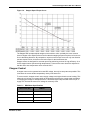
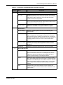
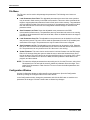
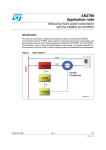
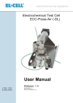
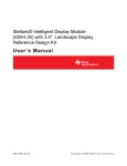
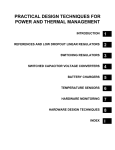
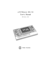
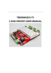
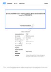
Stellaris® Stepper Motor Reference Design Kit User ’s Manual RDK-Ste ppe r-0 3 Co pyrigh t © 2 007– 200 9 Te xas In strumen ts Copyright Copyright © 2007–2009 Texas Instruments, Inc. All rights reserved. Stellaris and StellarisWare are registered trademarks of Texas Instruments. ARM and Thumb are registered trademarks, and Cortex is a trademark of ARM Limited. Other names and brands may be claimed as the property of others. Texas Instruments 108 Wild Basin, Suite 350 Austin, TX 78746 Main: +1-512-279-8800 Fax: +1-512-279-8879 http://www.luminarymicro.com 2 November 4, 2009 Stellaris® Stepper Motor RDK User’s Manual Table of Contents Chapter 1: Stellaris® Stepper Motor Reference Design Kit Overview ......................................................... 9 Using the RDK .................................................................................................................................................... 9 Features.............................................................................................................................................................. 9 Motor Technology ............................................................................................................................................. 10 Introduction to Stepper Motors...................................................................................................................... 10 Chopper Control............................................................................................................................................ 11 RDK Specifications ........................................................................................................................................... 12 Electrical ....................................................................................................................................................... 12 Mechanical.................................................................................................................................................... 12 Chapter 2: User Interfaces ............................................................................................................................. 13 On-board User Interface ................................................................................................................................... 13 Speed Mode.................................................................................................................................................. 14 Position Mode ............................................................................................................................................... 14 Graphical User Interface ................................................................................................................................... 15 File Menu ...................................................................................................................................................... 18 Configuration Window................................................................................................................................... 18 Chapter 3: Hardware Description .................................................................................................................. 21 Block Diagram .................................................................................................................................................. 22 Functional Description ...................................................................................................................................... 22 Microcontroller (Schematic Pages 1-2)......................................................................................................... 22 Output Power Stage (Schematic Page 3) ..................................................................................................... 23 Control Interfaces (Schematic Page 4) ......................................................................................................... 24 Software............................................................................................................................................................ 24 Chopper Control............................................................................................................................................ 24 Parameter Reference.................................................................................................................................... 26 Serial Protocol .................................................................................................................................................. 26 Appendix A: Parameters ................................................................................................................................ 27 Parameter Descriptions .................................................................................................................................... 27 Motor Running Configuration ........................................................................................................................ 28 Target Position .......................................................................................................................................... 28 Maximum Current ..................................................................................................................................... 28 Target Speed ............................................................................................................................................ 28 Acceleration .............................................................................................................................................. 28 Deceleration .............................................................................................................................................. 29 Motor Drive Configuration ............................................................................................................................. 29 Winding Resistance .................................................................................................................................. 29 PWM Frequency ....................................................................................................................................... 29 Fixed Rise Time ........................................................................................................................................ 29 Drive Current............................................................................................................................................. 30 Holding Current ......................................................................................................................................... 30 Control Mode ............................................................................................................................................ 30 Decay Mode .............................................................................................................................................. 31 Step Mode................................................................................................................................................. 31 Off Blanking Time ..................................................................................................................................... 31 November 4, 2009 3 Appendix B: Schematics................................................................................................................................ 33 Appendix C: PCB Component Locations ..................................................................................................... 39 Appendix D: Bill of Materials (BOM) ............................................................................................................. 41 4 November 4, 2009 Stellaris® Stepper Motor RDK User’s Manual List of Tables Table 1-1. Table 2-1. Table 2-2. Table 3-1. Table A-1. RDK Motor Specifications ............................................................................................................. 11 Description of GUI Main Window Controls .................................................................................... 16 Description of Configuration Controls............................................................................................ 19 Current Monitoring Circuits............................................................................................................ 23 Parameter Configuration Summary............................................................................................... 27 November 4, 2009 5 6 November 4, 2009 Stellaris® Stepper Motor RDK User’s Manual List of Figures Figure 1-1. Figure 1-2. Figure 2-1. Figure 2-2. Figure 2-3. Figure 3-1. Figure 3-2. Figure 3-3. Figure 3-4. Stepper Motor................................................................................................................................ 10 Stepper Speed-Torque Curve ....................................................................................................... 11 On-board User Interface................................................................................................................ 13 Stepper Main GUI Window............................................................................................................ 15 Configuration Window .................................................................................................................. 19 Stepper Motor Control RDK Layout............................................................................................... 21 Block Diagram ............................................................................................................................... 22 Chopper Waveform Generation .................................................................................................... 25 Current Control Software Flow ...................................................................................................... 25 November 4, 2009 7 8 November 4, 2009 C H A P T E R 1 Stellaris® Stepper Motor Reference Design Kit Overview Stellaris Reference Design Kits (RDKs) from Texas Instruments accelerate product development by providing ready-to-run hardware, a typical motor, and comprehensive documentation including hardware design files. Designers without prior motor control experience can successfully implement a sophisticated motor control system using the Stepper Motor Control RDK (Stepper RDK). Using the RDK The recommended steps for using the RDK are: Follow the Quickstart Guide included in the kit. The Quickstart guide will help you get the motor up and running in minutes. It also contains important safety information that should be read before using the RDK. Use the RDK GUI software to evaluate and optimize motor performance. The RDK GUI gives real-time access to more than a dozen operating parameters. Parameters and data transfer between the RDK control board and PC over a USB cable. Customize and integrate the hardware and software to suit an end application. This User's Manual and the Software Reference Manual are two important references for completing your project. Software can be programmed in the motor control board using either the RDK GUI software or using a JTAG debug interface (available from leading development tools vendors). Features The Stepper RDK's primary application is driving NEMA17, NEMA23, and NEMA34 stepper motors rated at up to 80 V at 3 Amps. The Stepper RDK uses software-based chopper control in order to operate the motor at both high torque and high-step rates. The Stepper RDK has the following features: Advanced chopper control of bipolar stepper motors Flexible platform accelerates integration process Fast and slow decay modes Full-Step, Half-Step, Micro-Step, and Wave modes High step rates up to 10,000 steps/sec (with suitable motor) Programmable holding current Integrated USB Virtual COM port Bootloader for firmware upgrades over serial port Support for external debugger through standard 20-pin ARM header November 4, 2009 9 Stellaris® Stepper Motor Reference Design Kit Overview Motor Technology Introduction to Stepper Motors Stepper motors are synchronous DC motors which rotate in precise increments as their coils are energized. Stepper motors typically have step angles of 0.9°, 1.8°, 7.5°, or 15°. The motor in the RDK has a step angle of 1.8° for a total of 200 steps per revolution. Figure 1-1 shows a detailed photo of the NEMA23 stepper motor included in the RDK. There are several different families of steppers motors, some with and some without permanent magnets (PM). The most common type in industrial applications is known as a hybrid stepper motor because it combines attributes from PM and non-PM motor construction. Figure 1-1. Stepper Motor Double-stack motor has 2 sets of magnets 50 rotor teeth on each pole Stator teeth North pole South pole Stator coils Front bearing Shaft The rotor on a hybrid stepper motor typically has 200 teeth made from a suitable magnetic material and surrounding one or more powerful embedded magnets. As the stator phase is energized, the opposing pole in the next rotor tooth is attracted, resulting in a single-step. Note that the torque curve of stepper motors is far from linear (see Figure 1-2). For each step, the motor develops peak torque when the rotor teeth are offset by one-quarter tooth pitch from the opposing pole in the energized phase. Also, overall motor torque drops considerably as motor speed increases. For this reason stepper motor torque is specified as the holding torque, or torque with no angular motion. 10 November 4, 2009 Stellaris® Stepper Motor RDK User’s Manual Figure 1-2. Stepper Speed-Torque Curve The Stepper RDK operates bipolar stepper motors with two coils—probably the most common class of stepper motor. Bipolar refers to the fact that the stepping sequence requires coil current to flow in alternating directions. By comparison, unipolar motors require current in only one direction and are simpler to drive, but have much lower torque for the same frame size. Stepper motors are designed for accurate open-loop positioning, and not for high efficiency. As a result, stepper motors operate at high temperatures. Current to the motor should be adjusted so that the motor case temperature never exceeds 100°C. Chopper Control A stepper motor can be operated at its rated DC voltage, but only low step rates are possible. This is because the current builds comparatively slowly in the stator coil. To overcome this, chopper control uses a supply voltage much higher than the motor's rating. This allows the coil current to increase rapidly to the desired level before the control starts modulating or chopping the voltage to maintain that level. This allows higher step rates with more torque. A supply of 5-20 times the motor’s DC voltage is commonly used. Table 1-1. RDK Motor Specifications Motor Frame Size NEMA23 Holding Torque 166 oz-in (1.29 Nm) Rated Current 2.8 A/phase Coil Resistance 0.75Ω Step Angle 1.8° November 4, 2009 11 Stellaris® Stepper Motor Reference Design Kit Overview RDK Specifications This reference design meets the following specifications. Electrical Supported motor type: Bipolar stepper Motor current (rated current per coil): 3 Amps Motor voltage (continuous coil voltage): 1-80 Vdc Supply Voltage: 9-80 Vdc Mechanical 12 PCB size: 4.6" x 2.8" x 0.75” (117 mm x 71 mm x 19 mm) No heat sink necessary November 4, 2009 C H A P T E R 2 User Interfaces The Stepper RDK firmware provides control of the stepper motor. It makes use of many of the features of the Stellaris microcontroller to perform the stepping function, reducing the number of external parts needed. In addition, the stepping firmware can be integrated with the user’s application, eliminating the need for separate microcontrollers for the stepping and application functions. The Stepper RDK firmware generates a stepping sequence as needed to run the motor at the specified speed. It also computes acceleration and deceleration ramps to smoothly change the motor speed between stopped and target speed. It switches voltage to the control signals of the H-bridge in order to drive the correct current to the motor windings at each step in a stepping sequence. The Stepper RDK firmware can be controlled in two ways. The simplest way is using the on-board interface, which allows the user control of the motor speed or position using controls available on the RDK board. For more complex control, a PC-hosted graphical program is available which not only allows setting of speed and position, but also a number of other parameters for tuning the motor operation (see “Graphical User Interface” on page 15). On-board User Interface The on-board user interface provides a way for the user to operate the stepper motor using just the controls provided on the stepper RDK board. The controls that can be used are a potentiometer, a push button, and two LEDs. See Figure 2-1 for a photo of the on-board controls. Figure 2-1. On-board User Interface Reset Button J T AG/SWD Connector Mode LED Status LED Power LED User Button November 4, 2009 Potentiometer 13 User Interfaces The on-board user interface can operate in two modes: Speed mode and Position mode. In Speed mode, the motor runs continuously at a speed and direction that can be controlled by the user. In Position mode, the motor runs to a position controlled by the user. The starting mode is Speed mode. The following on-board controls are available: Reset button: Restarts the stepper RDK software. The software enters Speed mode. User button: Switches between on-board UI modes, and starts and stops the motor. To change modes, hold down the user button for five seconds. To start and stop the motor, press and release the button. If a fault occurs (the status LED is blinking rapidly), press and hold the user button for five seconds to clear the fault. Doing this will not change modes. Potentiometer knob: The potentiometer is used to adjust the speed of the motor when Speed mode is used, and is used to adjust the position of the motor when Position mode is used. Mode LED: Informs the user which mode is selected by blinking a pattern. Status LED: Indicates the motor speed by blink rate. Also indicates a fault with rapid blinking. Speed Mode Upon entering Speed mode, the mode LED blinks one time. This is the default when the board is first powered, or after the reset button is pressed. To enter Speed mode from Position mode, press and hold the user button for five seconds, until the mode LED blinks one time. In Speed mode, the motor runs at a speed that is controlled by the position of the potentiometer knob. Upon entering Speed mode, the motor is stopped. To start the motor running, press the user button. The motor begins running in the forward direction. Forward is designated as clockwise. Use the user button to start and stop the motor. Each time the button is pressed, the motor either starts running if it is stopped, or stops if it is already running. Each time the motor starts running, it runs in the opposite direction from the previous time. The potentiometer knob is used to change the motor speed. The motor runs at a minimum speed of 10 steps/second when the knob is turned all the way to the left (counterclockwise), and at a maximum of about 1000 steps/second when the knob is turned all the way to the right (clockwise). The status LED blinks at a rate that varies according to the motor speed. Caution – Do not leave the motor running for long periods of time. If the motor is not attached to a heat sink, the case can get very hot, especially if a high drive current is used. Position Mode Upon entering Position mode, the mode LED blinks twice. To enter Position mode from Speed mode, press and hold the user button for five seconds, until the mode LED blinks two times. In Position mode, the motor always runs to a position that is determined by the position of the potentiometer. When the potentiometer is moved, the motor moves to the new position. The input from the potentiometer is scaled so that the motor turns one revolution (at 200 steps/revolution) as the knob is turned from one extreme to the other. The motor turns in the same direction as the potentiometer knob. In Position mode, the motor is enabled by default and turns as soon as the knob is turned. If the button is pressed, then the motor is disabled and does not run when the knob is turned. The motor can be re-enabled by pressing the user button again. 14 November 4, 2009 Stellaris® Stepper Motor RDK User’s Manual Graphical User Interface The stepper motor RDK board can be controlled from a graphical user interface (GUI) program running on a PC. Using the GUI provides much greater control of the motor than the on-board interface. Use the GUI to set specific values for position, speed, acceleration, and deceleration, as well as a number of other parameters to tune the operation of the motor. The GUI program communicates with the RDK board using a virtual serial port over a USB cable. Upon starting the GUI program, the on-board interface on the RDK board is disabled, and the knob and button have no effect. If the program has not been used before, then a dialog box appears that lets the user select the COM port to use. Once a COM port is selected, the program remembers the selection and does not ask again. However, at any time the user can re-open the COM port dialog box by double-clicking on the COM port indicator on the main panel. The stepper motor operation is controlled from the main window (see Figure 2-2). The main window provides user controls for controlling the motor, as well as several indicators to provide status of the motor operation. Most parameters can only be modified when the motor is stopped, and are not selectable while the motor is running. Table 2-1 describes the controls in detail. Figure 2-2. Stepper Main GUI Window 1 4 2 5 3 8 November 4, 2009 6 7 15 User Interfaces Table 2-1. Description of GUI Main Window Controls Item No. 1 2 3 4 5 16 Name Description Speed and Status Area Target Sets the motor running speed in steps per second. The desired speed can be typed into the box. If the motor is already running, it changes speed to match. Actual Indicates the actual motor running speed in steps per second. This value is calculated in the RDK firmware, it is not actually an independent measurement of motor speed. Status Indicates if the motor is stopped, running, accelerating, or decelerating. Drive Settings Area Drive Current Sets the value of the current that the motor control function should try to maintain in the motor winding when the winding is on during the step sequence. Accel Sets the rate at which the motor accelerates to the running speed, in steps/second2. The desired acceleration can be typed into the box. The new value is used the next time the motor needs to accelerate. Decel Sets the rate at which the motor decelerates from speed to stopped, in steps/second2. The desired deceleration can be typed into the box. The new value is used the next time the motor needs to decelerate. Position Area Target Sets the position of the motor, in steps. The motor position can be set in two ways: first, by entering a value in the Target Position box; or by clicking on the position slider and dragging it right or left to the desired position, and then releasing it. The position control is not available until the motor has been enabled using the Run button. Actual Shows the position of the motor, in steps. The position is shown both in the Actual box, and also on the slider control. There is an indicator on the upper slider that moves to show the actual motor position. Graph Area Speed Graph This strip chart shows the speed of the motor over time. The entire graph shows 30 seconds of motor speed history. The graph is signed, showing the direction as well as the speed of the motor. Current Graph This strip chart shows the current in the motor windings over time. The entire graph shows 30 seconds of winding current history. This graph shows the peak current in the windings, averaged between the two windings. The current data is only available when Chopper mode is used. If PWM mode is used, then this strip chart is grayed out. Position Slider Control Move the slider to adjust the motor’s position. The bottom part of the slider can be dragged with the mouse to set the target position. The upper part of the slider indicates the actual position. November 4, 2009 Stellaris® Stepper Motor RDK User’s Manual Table 2-1. Description of GUI Main Window Controls (Continued) Item No. 6 7 8 November 4, 2009 Name Description GUI Main Window Buttons Run button Enables the stepper motor for running. The stepper motor must be enabled before it can be used. The motor does not move immediately when the Run button is pressed. It only moves after the position control is used to set a new position. Stop button Stops the motor. If the motor is running, the motor decelerates to a stop. Once the Stop button has been clicked, the Run button must be clicked before the motor will operate again. Configure button Opens the Configuration window. The Configuration window is described in more detail in “Configuration Window” on page 18. Statistics Area DC Bus Voltage Shows the voltage supplied to the motor, as measured by the microcontroller. Motor Current Shows the peak current of the two windings, averaged together. This value is sampled when the windings are switched on. The current during the time when the windings are switched off is not measured, and that is not reflected in the measurement. The motor current is not available if PWM mode is used, and the current indicator will be grayed out. Processor Usage Indicates the microcontroller CPU load by percentage. Useful for estimating the loading of different applications and motor control algorithms. Temperature Indicates the internal temperature sensor of the microcontroller. Special Indicator Area COM Port Displays the COM port number, and status. If the indicator is shown in black, and displays a number for the COM port, then the serial port is opened. If the indicator is shown in red, and displays Err, then no COM port is opened. The COM port selection dialog box can be opened by double clicking on the COM port indicator. Target Displays the status of the target connection. If the Target is shown in black, and indicates Stepper, then the program is communicating with the RDK via the USB/serial port. If the indicator is shown in red, then there was a problem communicating with the target. Communication with the target can be restarted by double-clicking on the Target indicator. Fault Indicates that an overcurrent fault has occurred. Otherwise, the control is not visible. To clear the fault condition, double-click on the Fault indicator. 17 User Interfaces File Menu The File menu can be used to help manage the parameters. The following menu items are available: Load Parameters from Flash: The adjustable parameters that control the motor operation may be stored in flash memory in the RDK microcontroller. This menu choice commands the target to copy the parameters that were found in flash, into the active memory. The parameters are only loaded from flash if the motor is not running. If the parameters are loaded from flash, then the values shown on the main and configuration windows change to reflect the new parameter values. Save Parameters to Flash: Saves the adjustable motor parameters to the RDK microcontroller's flash memory. The parameters are only saved when the motor is not running. If a valid set of parameters have been saved to flash, those are loaded whenever the target is powered or reset. Load Parameters from File: The adjustable motor parameters can be loaded from a file that was previously saved. This menu choice reads the parameters from the file (if available) and sends them to the target. The parameters are only be loaded if the motor is stopped. Save Parameters to File: The adjustable motor parameters can be saved to a file. Selecting this menu choice causes all of the parameters to be read from the RDK board, and stored to a file. The parameters can only be stored to a file if the motor is not running. Update Firmware: This menu choice can be used to load new firmware onto the RDK target board. A file chooser dialog box opens to allow the user to select the firmware binary file to load to the target. This menu choice can only be used if the motor is not running. Once a file is chosen, the new firmware file is sent to the RDK, the RDK updates the flash with the new program, and then restarts. NOTE: To restore the default parameters that came with your kit, from the File menu, select Load Parameters from File and load the nema23_default.ini parameter file to the target. Then select Save Parameters to Flash from the File menu to save the default parameters into flash memory. Configuration Window Use the Configuration window to adjust specific motor parameters. Open the Configuration window by clicking the Configure button on the main window. In the Configuration window, change the parameters and click the OK button to send the new parameters to the target. Click the Cancel button to discard any changes. 18 November 4, 2009 Stellaris® Stepper Motor RDK User’s Manual Figure 2-3. Configuration Window 1 2 4 5 3 6 Table 2-2. Description of Configuration Controls Item No. 1 November 4, 2009 Name Description Control Mode Open-loop PWM In Open-loop PWM control mode, the firmware sets the PWM duty cycle to a value that corresponds to the desired current. The duty cycle is calculated based on the winding resistance and the bus voltage. There is no actual measurement of the winding current. In PWM mode, the Fixed Rise Time parameter can also be used (see Fixed Rise Time). Chopper In Chopper control mode, the microcontroller firmware monitors the current flowing in the winding, and switches the voltage to the winding on and off in order to keep the current at the desired value. Closed-loop PWM In Closed-loop PWM control mode, the firmware sets the PWM duty cycle based on the measurement of the current flowing in the winding. If the current is below the desired setting, then the PWM duty cycle will be set to a large value, and is reduced as the measured current approaches the desired value. 19 User Interfaces Table 2-2. Description of Configuration Controls (Continued) Item No. 1 (cont.) Name Description Fixed Rise Time This value is used when Open-loop PWM control mode is chosen. This value controls the amount of time that the winding is left turned on at the beginning of a step, before PWM is used to control the current in the winding. This allows the current in the winding to rapidly rise at the beginning of the step. This value is specified in microseconds. It should be adjusted with care because if the amount of time is too long, then the current in the winding may exceed the rating for the motor. PWM Frequency This is the frequency used for PWM, when Open-loop or Closed-loop PWM control mode is chosen. Chopper Off Blanking Time This value is used to control how long the chopper leaves the voltage off, after it turns off the winding when the drive current threshold is reached. At the end of the blanking time, the winding is turned on again and the chopper resumes measuring the winding current. Motor Parameters 2 3 20 Decay Mode Slow In Slow Decay mode, during the time that no voltage is applied to the winding, the low-side switches on the H-bridge are closed. This allows current to continue to circulate in the winding and decay slowly. Fast In Fast Decay mode, during the time that no voltage is applied to the winding, all the switches are open. The current can no longer circulate and decays quickly. Step Mode Full With full stepping, voltage is always applied to both windings, and a four-step stepping sequence is used. Half With half stepping, the voltage is off during part of the stepping sequence, and an eight half-step stepping sequence is used. Micro With micro stepping, the whole step is divided into 8 micro-steps. The current applied to the windings is varied sinusoidally, piecewise at each micro-step time. Wave Wave stepping is the same as full stepping, except that voltage is applied to only one winding at a time. 4 Holding Current This is the amount of current that should be applied to the windings when the motor is stopped. This increases the holding torque of the motor. Typically this value should be 0, or a fraction of the drive current. 5 Winding Resistance This is the winding resistance of the motor that is used. This value should be entered by the user if the motor type is changed. This value is used in order to calculate the correct PWM duty cycle if PWM control mode is used. 6 Maximum Current Sets a fault current level. If the current rises above this level, the hardware triggers a fault and places the motor in a safe configuration. November 4, 2009 C H A P T E R 3 Hardware Description Key components in the reference design include a Stellaris LM3S617 microcontroller with an ARM Cortex-M3 core and a power stage consisting of Fairchild Semiconductor’s gate drivers and MOSFETs. Other complementary components complete the design by providing protection, signal acquisition, and power supply functions. The entire circuit is built on a simple two-layer printed circuit board (see Figure 3-1). All design files are provided in the RDK CD. Figure 3-1. DC Power In Stepper Motor Control RDK Layout Output to Motor USB Interface DC Bus Capacitors Fairchild MOSFETs Fuse Gate Drivers Power Supplies JTAG Port Stellaris Microcontroller Speed Pot Mode Switch November 4, 2009 21 Hardware Description Block Diagram Figure 3-2. Block Diagram 9-80V DC IN +15V +3.3V Switching Power Supply Switching Power Supply DC Bus Capacitors H I J Linear Hall-effect Sensor F USB Potentiometer (Speed/Pos Adjust) E DC Voltage Sense Current Sense RxD TxD USB to Serial G / 2 Mode Push Switch High/Low Side Gate Driver B MOSFET Pair C High/Low Side Gate Driver B MOSFET Pair C High/Low Side Gate Driver B MOSFET Pair C High/Low Side Gate Driver B MOSFET Pair C Motor A1 Current Sense Ampl. Motor A2 D Stellaris Microcontroller Spare GPIO A / 14 JTAG/SWD / 4 Motor B1 Current Sense Ampl. Motor B2 D Current Sense Functional Description Stepper motor controls normally use a dedicated controller chip to implement a chopper-based drive stage. The microcontroller, if present, is there to manage position control and send step pulses to the controller. The RDK implements all of this functionality in the Stellaris microcontroller. One of the benefits of a software implementation is that the rest of the circuit is simple and can use standard power semiconductors. This section contains a detailed description of the RDK’s operation. See Appendix B, “Schematics” starting on page 33 for more details. Microcontroller (Schematic Pages 1-2) At the core of the Stepper Motor RDK is a Stellaris LM3S617 microcontroller. This part has a peripheral set optimized for motor control, including 6 high-speed ADC channels, a motor control PWM block, and an analog comparator. The RDK has a 20-pin ARM JTAG port for programming and debugging. A standard debug interface can be connected to this header (J1). Unallocated GPIO signals from the microcontroller are routed to pads labeled P1-P19. Several peripheral blocks are available for external use including SPI and UART1. The I/O pads are on a 0.1" grid to allow standard headers to be installed. 22 November 4, 2009 Stellaris® Stepper Motor RDK User’s Manual Also on this page are several LED status indicators, a simple reset circuit, and on-board user interface. The speed/position potentiometer's value is read by the microcontroller's ADC. Because the ADC's input span is 0-3 V, a resistor (R14) is used to pad the potentiometer voltage. The microcontroller's on-chip analog comparator provides an over-current trip function. Diodes D2 and D3 gate the greater of the two motor coil currents into an R/C network which connects to the inverting comparator input. Inside the microcontroller, this level is compared to a programmable voltage reference. An interrupt will be generated in the event of an over-current condition allowing the software to quickly shut-down the power stage. Output Power Stage (Schematic Page 3) The power stages on schematic pages 3 and 4 are identical. One power stage is used for each of the two coils in the bipolar stepper motor. The power stage consists primarily of a MOSFET H-bridge and associated gate drivers. The H-bridge allows the microcontroller to control the magnitude and polarity of the current in the motor. Each H-bridge has three logic control signals. PH_x1 and PH_x2 control whether the high-side or low-side switch is on. A common active-low enable signal can force all switches off. To turn on the high-side MOSFETs, the gate voltage must be driven higher than the source. This is achieved by using a gate driver and a flying-[or bootstrap] capacitor. Using Phase A1 as an example: When the low-side MOSFET (Q4) is ON, diode D7 is forward biased and capacitors C16 and C18 charge to almost 15 V. In turn, this charge allows the high-side MOSFET (Q3) to be turned on by the high-side gate driver. As the high-side MOSFET turns on, its source voltage rises taking the negative terminal of the flying capacitor along with it. The capacitor is sized to maintain a high-side supply voltage of at least HVDC + 12.5 V during the ON state. If the capacitor discharges below 11.3 V (typ), the SPM's under-voltage lock-out circuit activates to prevent the MOSFET from moving outside its safe operating area (SOA). Two 100mΩ resistive shunts provide 100 mV/A current sensing. The resultant voltage is fed into an operation amplifier and into the comparator circuit on Page 2. Table 3-1. Current Monitoring Circuits Microcontroller Comparator Microcontroller ADC Function Software programmable current trip Measurement of phase current amplitude Amplifier Gain n/a 11 Resolution 137.5 mV (1.375 A) 10 bits Scale 100 mV/A – 0.15 V 1 bit = 2.67 mA Trip Threshold (typ.) Programmable reference In software Trip Speed (typ.) <10 us Software-dependent Page 3 also shows a linear hall-effect sensor for positional feedback. This circuit is not presently populated. November 4, 2009 23 Hardware Description Control Interfaces (Schematic Page 4) The Stepper RDK has three power supply rails. The input power source is used directly to provide motor power and has a wide operating range. The exact supply voltage is not critical because the chopper control maintains constant motor current. Unregulated supplies can be used successfully. The microcontroller can monitor the input voltage level using a simple Vsense circuit, however, this measurement is not needed for the chopper control algorithm. A simple step-down switching regulator directly generates 3.3 V for the microcontroller. The +15 V gate driver power supply comes from a second stage boost converter, in this case a FAN5331 device from Fairchild semiconductor. Finally, a FT232RL device provides a USB virtual COM port. The virtual COM port is a fast and reliable method of communication between the motor control board and the RDK GUI software. The protocol description can be found in the Software Reference Manual and could be used as a general purpose control method from other hosts. Software The Stepper Motor Control RDK software manages four primary functions: Motor current control: Real time chopper control of motor current Motor step sequencing: Controlling the stepper motor’s commutation sequence Motor velocity and position control: Calculates motor speed as it advances to a new position Serial communication: Command and measurement exchange with host device The user can add software to implement additional functions that take advantage of the unused microcontroller peripherals or integrate the stepper control code with a custom application. Chopper Control Figure 3-3 shows how the chopper waveform is generated. GPIO signals from the microcontroller turn on the MOSFET switches, causing the motor current to start to build. The rate of increase in motor current is dependent on motor characteristics, motor load, and the supply voltage. Once the ADC detects that the current has exceeded the threshold, a blanking time commences. The blanking time allows the current to collapse slightly before the cycle repeats. 24 November 4, 2009 Stellaris® Stepper Motor RDK User’s Manual Figure 3-3. Chopper Waveform Generation Blanking Time Blanking Time High-side MOSFET ON Control Signal to Gate Driver Low-side MOSFET ON ADC Sampling Current Threshold Motor Winding Current (Amps) Start of step Chopping continues to end of step A summary of the current control software is shown in Figure 3-4. This technique could be applied to other loads that benefit from a constant current control. Figure 3-4. Current Control Software Flow ADC Interrupt (ISR) Timer Interrupt (ISR) Read ADC Sample Turn control pin ON Sample > Current Threshold? N Start new acquisition Start ADC acquisition Y Turn control pin OFF Exit ISR Start OFF blanking timer Exit ISR November 4, 2009 25 Hardware Description In addition to eliminating a dedicated chopper control IC, software-based chopper control makes it possible to easily change the current set-point. As an example, the RDK GUI has several parameters that change chopper control behavior for motors and loads that have differing characteristics. Parameter Reference See Appendix A, “Parameters,” on page 27 for a detailed description of the RDK’s parameters. Serial Protocol See the Stepper Motor Control RDK Software Reference Manual for more information. 26 November 4, 2009 A P P E N D I X A Parameters Table A-1 provides a summary of all configuration parameters. See “Parameter Descriptions” on page 27 for more information. Table A-1. Parameter Configuration Summary Parameter Name ID Units Range Default See Motor Running Configuration Parameters Target Position PARAM_TARGET_POS whole steps -8388608–8388607 0 page 28 Maximum Current PARAM_MAX_CURRENT mA 1000–10000 4000 page 28 Target Speed PARAM_TARGET_SPEED steps/sec 10–10000 200 page 28 Acceleration PARAM_ACCEL steps/sec2 100–60000 30000 page 28 Deceleration PARAM_DECEL steps/sec2 100–60000 60000 page 29 Motor Drive Configuration Parameters Winding Resistance PARAM_RESISTANCE mΩ 100–5000 750 page 29 PWM Frequency PARAM_PWM_FREQUENCY Hz 16000–32000 20000 page 29 Fixed Rise Time PARAM_FIXED_ON_TIME μS 1–10000 800 page 29 Drive Current PARAM_DRIVE_CURRENT mA 100–3000 1500 page 30 Holding Current PARAM_HOLDING_CURRENT mA 0–3000 0 page 30 Control Mode PARAM_CONTROL_MODE choice Chopper, Open-loop or Closed-loop PWM Chopper page 30 Decay Mode PARAM_DECAY_MODE choice Fast or Slow Slow page 31 Step Mode PARAM_STEP_MODE choice Full, Half, Micro, or Wave Half page 31 Off Blanking Time PARAM_BLANK_OFF μS 20–10000 100 page 31 Parameter Descriptions This section describes parameter configuration in detail. The parameters are grouped into two areas: Motor Running Configuration parameters and Motor Drive Configuration parameters. November 4, 2009 27 Motor Running Configuration Target Position ID PARAM_TARGET_POS Units Range Default whole steps -8388608–8388607 0 This parameter indicates the target position which is represented internally as a signed 24-bit number. It starts at position 0 and can run to the positive maximum or negative minimum of the range. Maximum Current ID PARAM_MAX_CURRENT Units Range Default mA 1000–10000 4000 This parameter sets the trip point for a hardware comparator. If the current exceeds this value, the comparator triggers a fault and places the motor in a safe configuration. Target Speed ID PARAM_TARGET_SPEED Units Range Default steps/sec 10–10000 200 This parameter sets the target speed of the motor. When moving, the motor accelerates up to this speed and remains at this speed until near the target position, at which time it decelerates to a stop. This value is in whole steps, so if Half-Stepping mode is used, then the actual stepping rate applied to the motor will be twice this value. It may be difficult to get the stepper motor up to maximum speed if it does not have a load. Acceleration ID PARAM_ACCEL Units Range Default steps/sec2 100–60000 30000 This parameter is the rate at which the motor accelerates to reach the target speed. Larger values work better if the motor has no load, avoiding the resonant frequencies. If the motor has much load, then this value may need to be lowered. 28 November 4, 2009 Stellaris® Stepper Motor RDK User’s Manual Deceleration ID PARAM_DECEL Units Range Default steps/sec2 100–60000 60000 This parameter is the rate at which the motor decelerates from the target speed to stop at the target position. Typically, the motor can decelerate faster than accelerate since the load and friction are working to help decelerate the motor. Motor Drive Configuration Winding Resistance ID PARAM_RESISTANCE Units Range Default mΩ 100–5000 750 This parameter sets the resistance of the winding. It should be obtained from the motor specification. This value is used in calculating the correct duty cycle if PWM mode is used. PWM Frequency ID PARAM_PWM_FREQUENCY Units Range Default Hz 16000–32000 20000 If PWM mode is used, this parameter determines the PWM period. Fixed Rise Time ID PARAM_FIXED_ON_TIME Units Range Default μS 1–10000 800 If PWM mode is used, this parameter sets the amount of time at the beginning of a step that the winding is left with full voltage applied before PWM is used to control the current. By leaving the full voltage applied to the winding, the current rises as fast as possible, allowing it to reach the drive current faster. Caution – If making adjustments to this value, do not exceed the motor’s rated current. Use lab equipment to measure the current in the winding when making adjustments to this value. November 4, 2009 29 Drive Current ID PARAM_DRIVE_CURRENT Units Range Default mA 100–3000 1500 This parameter sets the current level in the winding when the motor is running. If the Chopper mode is used, then the chopper switches the voltage to the winding off and on in order to maintain this current level. If the PWM mode is used, then the duty cycle is calculated to maintain this current level. This value should not necessarily be set to the rated current of the winding. For an unloaded motor, the best current setting varies with motor speed, with less current needed for running at lower speeds. Caution – If the motor is run for long periods of time with currents approaching the rated current for the winding, the motor can become very hot. Use caution around the motor if a heat sink is not being used. Holding Current ID PARAM_HOLDING_CURRENT Units Range Default mA 0–3000 0 This parameter sets the current in the winding when the motor is not running. By applying current to the winding when the motor is stopped, the holding torque of the motor can be increased. Typically, this should just be a fraction of the drive current, or zero. Control Mode ID PARAM_CONTROL_MODE Units Range Default choice Chopper, Open-loop or Closed-loop PWM Chopper This parameter specifies Chopper mode or PWM mode. Chopper mode monitors the winding current while the winding is on. When the current reaches the target value (Drive Current), it switches the winding off. The winding remains off for the Off Blanking Time. At the end of the blanking time, the winding is turned on again, and the current monitoring resumes. In Open-loop PWM mode, the duty cycle is calculated to set the voltage applied to the winding such that the target Drive Current flows in the winding. However, this is for a steady state situation, and when the motor is turning, its impedance changes dynamically. This means that the PWM current control is not precise. Also, by applying less than the full bus voltage to the winding when it is turned on, it can take a long time before the drive current is reached. For this reason, the winding can be left with full voltage applied for a duration at the start of a step. This is controlled by the Fixed Rise Time parameter. When using Open-loop PWM mode, current monitoring is not available. 30 November 4, 2009 Stellaris® Stepper Motor RDK User’s Manual Closed-loop PWM mode combines the features of Chopper and Open-loop PWM modes. Closed loop PWM mode uses a programmed PWM duty cycle to set the current. However, the current is also measured each time a PWM pulse is applied, and the duty cycle is adjusted to compensate for variation in the measured current compared to desired drive current. Decay Mode ID PARAM_DECAY_MODE Units Range Default choice Fast or Slow Slow This parameter specifies Fast Decay mode or Slow Decay mode. In Slow Decay mode, the H-bridge low-side switches are closed to remove voltage from the winding. This allows current to circulate in the winding and decay slowly. In Fast Decay mode, all the switches are opened to remove voltage from the winding, and the current decays rapidly. For the unloaded motor, slow decay seems to work best. Step Mode ID PARAM_STEP_MODE Units Range Default choice Full, Half, Micro, or Wave Half This parameter specifies the stepping mode. In Full-Step mode, full positive or negative current is applied to the windings at each point in the four-step stepping cycle. In Half-Step mode, the winding current is full negative, positive, or 0 at each point in an eight half-step stepping sequence. In Micro-Step mode, the current in each winding is varied sinusoidally over a sequence of 8 microsteps per step. In Wave-Step mode, full steps are made as in Full-Step mode, except that only one winding is energized at a time. The unloaded motor runs smoother at slower speeds using half stepping, but full stepping may be appropriate for higher speeds. For very slow speeds, less than 200 steps per second, Micro-Step mode may be used to smooth out the motion of the motor. Off Blanking Time ID PARAM_BLANK_OFF Units Range Default μS 20–10000 100 If Chopper mode is used, this parameter sets the amount of time that the winding remains off after the winding current reaches the drive current. Caution – Great care should be taken if decreasing this value. If the off-blanking time is not long enough, the current may not drop enough between the times when the voltage is applied, and the current can continue to rise in the winding, above the rated current. Use lab equipment to observe the winding current when making adjustments to this value. November 4, 2009 31 32 November 4, 2009 A P P E N D I X B Schematics This section contains the schematics for the LM3S1968 Evaluation Board: Contents Page on page 34 Microcontroller on page 35 Driver - Coil A on page 36 Driver - Coil B on page 37 Power Supplies and USB on page 38 November 4, 2009 33 Contents Page 1 2 3 4 5 6 History Revision U_Stepper Microcontroller Stepper Microcontroller.SchDoc A U_Stepper Ph A Drive Stepper Ph A Drive.SchDoc U_Stepper Ph B Drive Stepper Ph B Drive.SchDoc Date Description 0 Jan 17, 07 First Full Release 0.1 Feb 07, 07 Change USB device to bus power. A Feb 09, 07 First Production Revision A.1 Jul 10, 07 Change C18, C19, C31, C32 to no-populate A U_Stepper Power Supplies Stepper Power Supplies.SchDoc B B C C D D Drawing Title: Stepper Motor Reference Design Kit Page Title: Contents Page Size Date: 1 2 3 4 5 B Document Number: 7/10/2007 Sheet 6 1 of 5 Rev A.2 Microcontroller 1 2 3 4 5 6 TP7 FAULT +3.3V R16 10K U1 VCP_RX VCP_TX A PA2/SSIClk PA3/SSIFss PA4/SSIRx PA5/SSITx 17 18 19 20 21 22 TCK/SWCLK TMS/SWDIO TDI TDO PC4/CCP5 PC5/CCP1 PC6/CCP3 PC7/CCP4 40 39 38 37 14 13 12 11 SPEED_CTRL ADC5 1 2 3 4 48 47 OSC0 OSC1 9 10 PA0/U0Rx PA1/U0Tx PA2/SSIClk PA3/SSIFss PA4/SSIRx PA5/SSITx PB0/PWM2 PB1/PWM3 PB2 PB3/FAULT PB4/C0PB5/C0o PB6/C0+ PB7/TRST PC0/TCK/SWCLK PC1/TMS/SWDIO PC2/TDI PC3/TDO/SWO PC4/CCP5 PC5/CCP1 PC6/CCP3 PC7/CCP4 PD0/PWM0 PD1/PWM1 PD2/U1Rx PD3/U1Tx PD4/CCP0 PD5/CCP2 ADC0 ADC1 ADC2 ADC3 ADC4 ADC5 PE0/PWM4 PE1/PWM5 29 30 33 34 44 43 42 41 25 26 27 28 45 46 SWUSR Mode Push Button SWUSR PH_B1 PH_B2 +3.3V ISENSEAB PB6/C0+ PB7/nTRST PD2/U1Rx PD3/U1Tx LEDSTATUS LEDMODE SW2 SW-PB R6 10K PH_A1 PH_A2 R11 LEDSTATUS +3.3V 35 36 D4 Green R12 R1 47K RESETn 5 Y1 Reset SW1 SW-PB C1 1UF 8 16 24 31 6.00MHz C2 C3 18PF 18PF Mode LED 220 PH_A_ENn PH_B_ENn D5 Green R10 +3.3V D1 S100 B Status LED 220 LEDMODE I_PHA I_PHB POSITION VSENSE Power LED 220 OSC0 OSC1 RST LDO GND GND GND GND VDD VDD VDD VDD +3.3V 7 15 23 32 +3.3V C5 C6 C7 C8 C9 C10 0.01UF 0.1UF 0.01UF 0.1UF 0.01UF 1UF LM3S617 R14 4.7K SPEED_CTRL C52 +3.3V +3.3V R4 10K PC4/CCP5 GND PC5/CCP1 GND +3.3V GND PC6/CCP3 PC7/CCP4 PA2/SSIClk PA3/SSIFss PA4/SSIRx PA5/SSITx PB6/C0+ PB7/nTRST PD2/U1Rx PD3/U1Tx ADC5 GND +15V D2 ISENSEA S100 D3 R2 ISENSEAB 1.0K C4 ISENSEB S100 0.01UF R3 261K B D6 Green LDO 6 C A R15 50K Speed/Position Control Pot 1UF R5 10K +3.3V C P1 P2 P3 P4 P5 P6 P7 P8 P9 P10 P11 P12 P13 P14 P15 P16 P17 P18 P19 R7 10K J1 +3.3V 20 18 16 14 12 10 8 6 4 2 R8 10K R9 10K 19 17 15 13 11 9 7 5 3 1 R13 10K RESETn TDO TCK/SWCLK TMS/SWDIO TDI 2X10 HEADER JTAG/SWD GPIO Expansion Header JTAG/SWD Debugger Header Connect Optional Limit Switches to P1-2 and P3-4 D D Drawing Title: Stepper Motor Reference Design Kit Page Title: Microcontroller Size Date: 1 2 3 4 5 B Document Number: 7/10/2007 Sheet 6 2 of 5 Rev A.2 Driver - Coil A 1 2 3 4 5 6 +15V A 7 20K GND R19 R23 Q3 FDMS3672 4 0.1UF Q5 FDMS3672 Q1-8 Can subst FDS3672 in SOIC package 4 MOTOR_A1 R24 5 LO 1, 2, 3 1, 2, 3 100 MOTOR_A2 100 U2 FAN73832 2 100PF DT/SDn C18 10uF 25V 6 VS PH_A_ENn + C16 5, 6, 7, 8, 9 IN HO Q1-8 Can subst FDMS3682 for lower Rds(on) OMIT 0.1UF 3 NOTES: C22 8 VB R17 10K C11 VMOTOR S100 5, 6, 7, 8, 9 PH_A1 33 5, 6, 7, 8, 9 C14 0.1UF 1 Q1 FDV310N D7 R21 4 C13 10uF 25V VDD + 5, 6, 7, 8, 9 A Q4 FDMS3672 B R29 OMIT 2 1, 2, 3 B +3.3V 4 1, 2, 3 4 Q6 FDMS3672 R28 +15V C15 0.1UF 33 S100 4 4 1 1 I_PHA C21 R27 0.1 1W 5 R22 3 1K D8 U5 FAN4174IS5X_NL 1NF +3.3V 1 PH_A2 VDD C23 8 VB 0.1UF 7 HO 100PF DT/SDn R20 20K R25 R31 R30 10K 6 R26 5 LO 100K 100 C ISENSEA U3 FAN73832 2 Q2 FDV310N C GND 3 C19 10uF 25V 100 VS C12 + C17 IN R18 10K 1UF OMIT TP3 TP4 TP5 TP6 A1 A2 B1 B2 M1 +3.3V U4 MOTOR_A2 MOTOR_A1 MOTOR_B1 MOTOR_B2 Green N J2 Black 4 3 White 2 1 VCC C20 0.1UF OUT GND S 43045-0409 Red 1 2 POSITION 3 A1301 Rotating Permanent Magnet (optional) D D MOTOR-NEMA23-OUTLINE Stepper Motor Connections Linear Hall-Effect Position Sensor Drawing Title: Stepper Motor Reference Design Kit Page Title: Driver - Coil A Size Date: 1 2 3 4 5 B Document Number: 7/10/2007 Sheet 6 3 of 5 Rev A.2 Schematic Driver - Coilpage B 1 1 2 A 3 4 5 6 A +15V 7 HO R38 Q9 FDMS3672 4 Q11 FDMS3672 0.1UF 4 MOTOR_B1 R39 5 LO 1, 2, 3 1, 2, 3 100 MOTOR_B2 100 5, 6, 7, 8, 9 20K GND R34 U6 FAN73832 2 100PF DT/SDn C31 10uF 25V 6 VS Q7 FDV310N + 0.1UF 3 PH_B_ENn OMIT C29 5, 6, 7, 8, 9 C34 8 VB IN R32 10K C24 VMOTOR S100 Q10 FDMS3672 Q12 FDMS3672 +3.3V B R44 OMIT 2 1, 2, 3 4 1, 2, 3 4 B 5, 6, 7, 8, 9 1 PH_B1 33 D9 5, 6, 7, 8, 9 C27 0.1UF 4 C26 10uF 25V VDD + R36 R43 +15V 4 33 I_PHB C33 R42 0.1 1W S100 4 1 1 5 R37 C28 0.1UF U8 FAN4174IS5X_NL 3 1K D10 1NF +3.3V PH_B2 VDD C35 1 VB IN 0.1UF HO Q8 FDV310N C25 100PF R35 20K DT/SDn LO + C32 10uF 25V R40 R46 100 R45 10K 6 100K R41 5 100 C ISENSEB U7 FAN73832 2 3 GND VS 7 1UF OMIT C30 R33 10K C 8 D D Drawing Title: Stepper Motor Reference Design Kit Page Title: Driver - Coil B Size Date: 1 2 3 4 5 B Document Number: 7/10/2007 Sheet 6 4 of 5 Rev A.2 Power Supplies and USB 1 A 10-80VDC POWER INPUT 2 3 4 5 6 TP1 VIN 1 3 2 PJ-002BH-SMT A U10 FB2 F1 J3 VMOTOR C45 8 VIN VCC RON/SD BST 7 BLM21P221SG 4A R49 261K C36 D11 S100 0.1uF VSENSE TP2 C38 0.1uF C41 150UF + 100V GND FB3 0.01uF R51 + C43 C42 150UF 100V 0.1uF R50 10K 6 261K 2 C44 +3.3V 0.01uF R52 3 100K BLM21P221SG 4 RCL SW RTN FB L1 1 5 D12 S100 R55 0 OHM 330uH DR127-331 R53 309 + LM5008MM C47 10uF 25V R54 1.0K 3.3V 300mA Switching Regulator B B J4 USB MINI B RECEPTACLE 5V FB1 D- D+ ID +15V G 6 7 DR73-100R 10uH C37 5 4 3 2 OMIT 1 D13 L2 +3.3V S100 U11 0.1UF 5 VIN SW 1 C49 R56 150K 100pF + U9 C39 1UF 4 20 16 15 R47 4.7K 8 19 24 R48 10K 27 28 17 VCCIO VCC TXD RXD USBDM USBDP RTSn CTSn DTRn DSRn DCDn NC RESETn NC RIn OSCI OSCO 3V3OUT C40 0.1UF + FT232RL AGND GND GND GND TEST C C48 10uF 25V CBUS0 CBUS1 CBUS2 CBUS3 CBUS4 1 5 VCP_RX VCP_TX C46 10uF 25V FB 4 3 11 2 9 10 SHDNn GND 3 C50 10uF 25V C51 0.1UF C R57 13.3K 2 FAN5331 6 +15V 30mA Power Supply for Gate Drive 23 22 13 14 12 25 7 18 21 26 + USB Virtual COM Port D D Drawing Title: Stepper Motor Reference Design Kit Page Title: Power Supplies and USB Size Date: 1 2 3 4 5 B Document Number: 7/10/2007 Sheet 6 5 of 5 Rev A.2 A P P E N D I X C PCB Component Locations This section shows the PCB component locations for the Stepper Motor RDK. November 4, 2009 39 Power Supplies and USB A P P E N D I X D Bill of Materials (BOM) This section provides the BOM for the Stepper Motor RDK. November 4, 2009 41 Texas Instruments Stepper Motor Reference Design Kit Bill Of Materials Rev A Issue 3 6/10/07 Item Ref Qty Part Number Description 1 C1, C10, C23, C35, C39, C52 C11, C12, C24, C25, C49 C13, C26, C46, C47, C48, C50 C2, C3 6 C0805C105Z4VACTU Capacitor 1uF 16V Y5V 0805 Kemet Capacitor 100pF 50V 10% Ceramic 0805 Kemet 2 3 4 Mfg 6 EEE-FK1E100R Capacitor, 10uF 25V Electro, Low Z, SMT Size B Panasonic 2 C0805C180J5GACTU Capacitor 18pF 50V 5% 0805 NPO Kemet Capacitor 1000pF 50V 10% Ceramic 0805 Capacitor, 0.01uF 16V 10% 0805 X7R Kemet C21, C33 C4, C5, C7, C9, C44, C45 C41, C42 2 6 14 C0805C104J5RACTU 4 C1206C104K1RACTU Capacitor, 0.1uF 100V 10% 1206 X7R S100 Diode Schottky 100V 2A Fairchild 11 12 13 C6, C8, C14, C15, C16, C17, C27, C28, C29, C30, C37, C38, C40, C51 C22, C34, C36, C43 D1, D2, D3, D7, D8, D9, D10, D11, D12, D13 D4, D5, D6 F1 FB2, FB3 Capacitor, 150uF 50V Electro, Low Z, SMT Size G Capacitor, 0.1uF 50V 5% 0805 X7R 3 1 2 LTST-C171GKT 154004 BLM21PG221SN1D LED, 0805 SMT Green Fuse, SMT in holder 4A Inductor, Chip Ferrite 2A 0805 220 Ohm@100MHz LiteOn Littelfuse Murata 14 J1 1 N2520-6V0C-RB-WE Header, Low profile Shrouded 2x10way SMT 15 J2 1 43045-0409 Connector, MicroFit 3mm 4pos header R/A SMT 16 J3 1 PJ-002AH-SMT Connector, 2.1mm DC power socket SMT 17 18 19 20 21 J4 L1 L2 Q1, Q2, Q7, Q8 Q3, Q4, Q5, Q6, Q9, Q10, Q11, Q12 R4, R5, R6, R7, R8, R9, R13, R16, R17, R18, R30, R32, R33, R45, R48, R50 R1 R10, R11, R12 R14, R47 R15 1 1 1 4 8 54819-0572 DR127-331-R DR73-100-R FDV301N FDMS3672 Connector, USB Mini-B SMT 5pin Inductor, 330uH Power SMT Inductor, 10uH Power SMT Mosfet, N-Ch SOT-23 Mosfet, Dual N-Ch 100V 5.1A SO-8 5 6 7 8 9 10 22 22a 23 24 25 26 27 28 29 30 31 32 42 5 Edison Project 2 10 EEV-FK2A151M 16 1 3 2 1 Resistor 10K 5% 0805 EVU-TUAB16B54 Resistor 47K 5% 0805 Resistor 220 Ohms 5% 0805 Resistor 4.7K 5% 0805 Trimpot, 16mm thumbwheel style SMT 50K Panasonic Kemet Kemet 3M Molex CUI Molex Coiltronics Coiltronics Fairchild Fairchild Generic Generic Generic Generic Panasonic R19, R20, R34, R35 R2, R28, R43, R54 4 Resistor 20K 1% 0805 Generic 4 Resistor 1.0K 1% 0805 Generic R21, R22, R36, R37 R23, R24, R25, R26, R38, R39, R40, R41 R3, R49, R51 R31, R46, R52 R57 4 Resistor 33 Ohms 5% 0805 Generic 8 Resistor 100 Ohms 5% 0805 Generic 3 3 1 Resistor 261K 1% 0805 Resistor 100K 5% 0805 Resistor 13.3K 1% 0805 Generic Generic Generic November 4, 2009 Stellaris® Stepper Motor RDK User’s Manual 33 34 35 36 R56 R53 R55 R27, R42 1 1 1 2 LR2512-LF-R100-F Resistor Resistor Resistor Resistor 150K 1% 0805 340 Ohms 1% 0805 Zero Ohm 5% 0805 0.1 Ohms 2W 2512 Generic Generic Generic IRC 37 SW1, SW2 2 B3S-1000 Switch, Momentary Tact SMT Omron 38 39 40 41 42 U1 U10 U11 U2, U3, U6, U7 U4 1 1 1 4 0 LM3S617-CQN25 LM5008MM FAN5331S FAN73832M A1301KLHLT-T IC, IC, IC, IC, IC, Microcontroller ARM Cortex TQFP48 Integrated Step-down converter Boost Converter SOT23-5 High-Low Side Gate Driver SO-8 Linear Hall Effect sensor SOT-23 OMIT Luminary National Fairchild Fairchild Allegro 43 U5, U8 2 FAN4174IS5X_NL Fairchild 44 U9 1 FT232RL 45 Y1 1 FOXSDLF/060-20 IC, Low-Power, Rail-to-Rail Output, 3MHz Op Amp SOT-23 USB UART Asynchronous Serial Data Transfer Chip, SSOP28 Pb-free Crystal, 6.00MHz HC49US SMT 46 PCB 1 SRDK-A PCB, FR-4 4.52" x 2.80" 2-layer Gloss black solder mask FTDI Fox Imagineering 150 Non-PCB Items 47 1 450-3825 Knob, Aluminum 1.50x0.63" for 1/4" shaft 48 1 STP-MTR-23055 Stepper Motor NEMA23 166oz-in with 12" cable 49 1 PSA15R-240P-R 50 1 RPBAG-R Wall Adapter 24Vdc 15W with interchangeable plug adapters Kit of 4 plugs (USA/EU, UK, Aust) 51 4 November 4, 2009 SJ-5018 (BLACK) Rubber Feet Black EPD SureStep Phihong Phihong 3M 43 44 November 4, 2009 IMPORTANT NOTICE Texas Instruments Incorporated and its subsidiaries (TI) reserve the right to make corrections, modifications, enhancements, improvements, and other changes to its products and services at any time and to discontinue any product or service without notice. Customers should obtain the latest relevant information before placing orders and should verify that such information is current and complete. All products are sold subject to TI’s terms and conditions of sale supplied at the time of order acknowledgment. TI warrants performance of its hardware products to the specifications applicable at the time of sale in accordance with TI’s standard warranty. Testing and other quality control techniques are used to the extent TI deems necessary to support this warranty. Except where mandated by government requirements, testing of all parameters of each product is not necessarily performed. TI assumes no liability for applications assistance or customer product design. Customers are responsible for their products and applications using TI components. To minimize the risks associated with customer products and applications, customers should provide adequate design and operating safeguards. TI does not warrant or represent that any license, either express or implied, is granted under any TI patent right, copyright, mask work right, or other TI intellectual property right relating to any combination, machine, or process in which TI products or services are used. Information published by TI regarding third-party products or services does not constitute a license from TI to use such products or services or a warranty or endorsement thereof. Use of such information may require a license from a third party under the patents or other intellectual property of the third party, or a license from TI under the patents or other intellectual property of TI. Reproduction of TI information in TI data books or data sheets is permissible only if reproduction is without alteration and is accompanied by all associated warranties, conditions, limitations, and notices. Reproduction of this information with alteration is an unfair and deceptive business practice. TI is not responsible or liable for such altered documentation. Information of third parties may be subject to additional restrictions. Resale of TI products or services with statements different from or beyond the parameters stated by TI for that product or service voids all express and any implied warranties for the associated TI product or service and is an unfair and deceptive business practice. TI is not responsible or liable for any such statements. TI products are not authorized for use in safety-critical applications (such as life support) where a failure of the TI product would reasonably be expected to cause severe personal injury or death, unless officers of the parties have executed an agreement specifically governing such use. Buyers represent that they have all necessary expertise in the safety and regulatory ramifications of their applications, and acknowledge and agree that they are solely responsible for all legal, regulatory and safety-related requirements concerning their products and any use of TI products in such safety-critical applications, notwithstanding any applications-related information or support that may be provided by TI. Further, Buyers must fully indemnify TI and its representatives against any damages arising out of the use of TI products in such safety-critical applications. TI products are neither designed nor intended for use in military/aerospace applications or environments unless the TI products are specifically designated by TI as military-grade or "enhanced plastic." Only products designated by TI as military-grade meet military specifications. Buyers acknowledge and agree that any such use of TI products which TI has not designated as military-grade is solely at the Buyer's risk, and that they are solely responsible for compliance with all legal and regulatory requirements in connection with such use. TI products are neither designed nor intended for use in automotive applications or environments unless the specific TI products are designated by TI as compliant with ISO/TS 16949 requirements. Buyers acknowledge and agree that, if they use any non-designated products in automotive applications, TI will not be responsible for any failure to meet such requirements. Following are URLs where you can obtain information on other Texas Instruments products and application solutions: Products Amplifiers Data Converters DLP® Products DSP Clocks and Timers Interface Logic Power Mgmt Microcontrollers RFID RF/IF and ZigBee® Solutions amplifier.ti.com dataconverter.ti.com www.dlp.com dsp.ti.com www.ti.com/clocks interface.ti.com logic.ti.com power.ti.com microcontroller.ti.com www.ti-rfid.com www.ti.com/lprf Applications Audio Automotive Broadband Digital Control Medical Military Optical Networking Security Telephony Video & Imaging Wireless www.ti.com/audio www.ti.com/automotive www.ti.com/broadband www.ti.com/digitalcontrol www.ti.com/medical www.ti.com/military www.ti.com/opticalnetwork www.ti.com/security www.ti.com/telephony www.ti.com/video www.ti.com/wireless Mailing Address: Texas Instruments, Post Office Box 655303, Dallas, Texas 75265 Copyright © 2009, Texas Instruments Incorporated