1
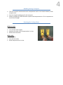
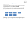
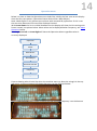
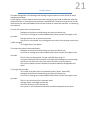
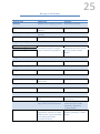
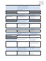
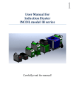
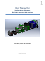
1 User Manual for Induction Heater INCOIL model IH series Carefully read the manual! Original instructions 2 Table of contents Introduction................................................................................................................................ 3 Handling During Transport ......................................................................................................... 4 Draining the Cooling Water .................................................................................................... 4 Handling Care and Maintenance ................................................................................................ 5 Cleaning................................................................................................................................... 5 Ventilation............................................................................................................................... 5 Service ..................................................................................................................................... 5 LOTO: Lock out, tag out .............................................................................................................. 6 Weekly maintenance .............................................................................................................. 6 Monthly maintenance............................................................................................................. 6 Yearly maintenance ................................................................................................................ 6 Explanation of Symbols .............................................................................................................. 7 Preparation / Installation ........................................................................................................... 8 Installation of the coil ............................................................................................................. 8 Installation / start up. ............................................................................................................. 8 Changing of the coil ................................................................................................................ 9 Functions .................................................................................................................................. 10 Control panel full version ......................................................................................................... 11 Menu structure of the control panel ....................................................................................... 12 Menu Operation ....................................................................................................................... 18 Menu Settings .......................................................................................................................... 19 Panel Locked ......................................................................................................................... 21 Menu Temperatures ................................................................................................................ 22 Menu Diagnostic ...................................................................................................................... 23 Menu Alarms ............................................................................................................................ 24 Message in the display ............................................................................................................. 25 Technical specifications............................................................................................................ 28 Warranty .................................................................................................................................. 29 Company details ....................................................................................................................... 30 Introduction This manual explains how the heater is controlled by the various buttons on the unit. The unit can be operated manually or via a PC / PLC. Supplied accessories: Power cord Inductor/tool/coil User manual Optional accessories: External water cooler Trolley Custom inductors Workstation with a balancer Transport box Water pump IR-sensor for Temperature control Machine fitting Deck Heater Flex Heater Push button cable 3 Handling During Transport The unit contains sensitive electronic components and it is not shock resistant, never drop the unit. Save the original packaging for safe transport. When transporting, drain the water system with compressed air. This is important to avoid frost damage. Draining the Cooling Water Without cooler Exit heating. Turn off the water supply Replace the water with compressed air in inlet. Blow out all the water With cooler Exit heating Shut off the cooler Blow compressed air in inlet. 4 Handling Care and Maintenance The unit contains sensitive electronic components and is not shock resistant, never drop the unit. Do not use the unit, when there is damage to the enclosure, power cord, and transformer with water-cooled cables or coil. There is dangerous voltage inside the unit, never open the unit. Do not insert objects into it. Make sure the power cord / hose package and coolant hoses are not squashed. In case of damage to the unit, contact your dealer. Do not place any object on the unit that contains water or other liquid and do not expose the unit to moisture. Do not use the unit in moist or dusty areas and don’t expose it to extreme heat (maximum 35 degrees). Do not cover the unit with subjects or others that might prevent cooling. Allow space at the back, sides and under the unit. Do not use deformed or repaired coils which can cause a short circuit or low water flow. If the unit is exposed to the cold, condensation can form, let it therefore remain unconnected indoors for an hour before it is used or connected. During electrical storms plugged in units can be damaged, therefore always pull the power cord. Never use the unit outdoors in wet weather. When the unit is not used for a long time, the power plug is to be pulled out and the water turned off. Metallic objects close to the coil can be heated. Do not heat too close to electrical equipment; it can be damaged by the magnetic field from the coil. People with pacemakers should never reside near magnetic fields. Cleaning Make the unit powerless. The unit should only be wiped with a damp cloth. The coil is cleaned of soot and dirt to prevent electrical arcing. Never rinse the unit since there is a risk that the water penetrates and destroys electronics. Ventilation All openings in the cabinet are for ventilation, don´t block or cover any of these; it also applies under the unit. Never insert objects into these openings. Replace the air filter in the front of the unit at regular intervals to ensure air flow, recommended replacement about 2-12 times a year depending on the environment. Service There are no parts that can be repaired by the user, at failure contact the dealer. 5 LOTO: Lock out, tag out When the machine must be powered down for maintenance, changing the coil or similar tasks, even in this powered down state the machine is never to be opened up. 1. Terminate any ongoing heating operation. 2. Turn off the main switch and lock it in its off position 3. If the unit is delivered with a separate cooler that is power from a separate power source then turn off the main switch of the cooler too. 4. Turn off the water flow to the machine. 5. Now the work around the machine is ready to proceed. Weekly maintenance Check the air filter, change if needed. Control the hose package for wear and tear injury. If the system is equipped with IR-pyrometer, check that its lens is clean. Clean the coil from soot and dirt. Cooler if installed: o Check that the radiator is free of dirt and dust. o Make sure that no debris or trash has fallen into it. Check water filter if installed. Monthly maintenance Check the water level in the cooler. Check the water quality. A cooler might have requirements to change the water on a regular basis. The Heater has no trouble running with the same water as long as the water is clean. Yearly maintenance All items are handled during more frequent maintenance. 6 Explanation of Symbols To get the best out of the unit, read instructions and safety before use. These symbols are placed on the unit's chassis: This symbol indicates that there is dangerous voltage inside the unit. . This symbol will alert you that there are important instructions for the handling, care and maintenance in the instructions that come with the product. This symbol indicates that people with pacemakers should not be staying close to magnetic fields. This symbol indicates that you should not stand on or charge the unit´s chassis with high weight. 7 Preparation / Installation Installation of the coil The contact surfaces of the coil and transformer must be undamaged and clean O-rings must be intact and of the right dimension (7x2,5mm standard transformer /6,1x1,6mm lightweight transformer) The nuts on the bayonet coupling should be easy to thread and be tightened with a torque 4 Nm to prevent leakage and provide good electrical contact. Transformer O-ring Coil Installation / start up. 1. Make sure that water of good quality (example: fresh water, process water) and electricity is available. 2. Arrange the workplace so that no cables, hoses or hose assembly is folded or squeezed. 3. The coil should be mounted. 4. Connect the water. 5. Turn on the water. 6. Check that there are no leaks (Paragraph 4-6 does not apply if equipment supplied with preinstalled coolers). 7. Make sure the main switch is turned off. 8. Connect External Control, external emergency circuit, IR-pyrometer and network if this is to be used. 9. Plug in the power cord and turn on the main switch. 10. Allow the machine to boot. 11. Now press the button "On / Off" to activate the heater and the cooling circuit. 12. Let the water flow through the cooling circuit and lower the handle to prevent air pockets to be formed in the transformer / coil (especially important when replacing the coil, if the machine has been drained of water, or are unused). 13. Check that no error message appears in the display window. 14. The machine is now ready for heating. 8 Changing of the coil 1. End heating, turn off the power to the machine, see “Lock out Tag out” above. 2. Loosen the nuts holding the coil. 3. Let the coil slide out of its mounting. Water will flow out of the coil as it is filled with water. This can be avoided by draining the cooling water, see “Draining the Cooling Water” above. Wipe up any water that runs out. 4. Check the coil and transformer according to “Installation of the coil” above. 5. Hold up the wings holding the coil and slide it into place. Tighten the nuts with 4 Nm of torque. 6. Wipe up any water after the assembly. 7. Turn on the water flow again. 8. Make sure that no leakage occurs in the coil connection. 9. Continue with items 9 to 14 in “Installation / start up.” above. 10.Check the water level of the cooler and fill up when needed. Mains switch Do turn off the machine using the mains switch under high load. First terminate any ongoing heating operation. Only then use the mains switch to turn off the machine. 9 Functions 10 The unit can be operated both manually and externally. It can also be run with programs. These can easily be created directly in the machine's display. It is also possible to create programs on the PC and then transfer to the machine Version L (Limited) can only be run manually. Manual Run startup procedure as defined previously. Heating can now be started using Button “1” on display, push button cable or handle button. Control the power with potentiometer on the unit or on the handle. Releasing the button stops the heating. External Relay signals can start/stop the unit. Also show current status: Ready to Heat, Heating and Error signal. It is also possible to control the machine using Modbus (RS232 or TCP/IP) Program First define program to be run. See “Heating Programs” in separate document. When a button is pressed the program will start. Releasing the button will NOT stop the program! Pressing the button for a second time will stop the program. 11 Control panel full version 1 1 1 1 1 1 1 1 1 1 2 1 2 3 4 5 6 7 8 9 10 11 12 13 14 15 16 17 18 3 4 5 6 7 ON/OFF Power potentiometer Switch Panel/Handle/External Test (power on) Panel contact ON/OFF Not currently used Connection temperature sensor IR-pyrometer External Control External Emergency Stop circuit Arrow down Arrow right Emergency stop Set/Confirm/Acknowledge Arrow up Arrow left Green = Heating Red = Current limit Orange = On Green = OK Red = Error Display window 8 X X X X X X X = Option 9 12 Menu structure of the control panel The menu consist of seven main pages where messages and measurements are presented, settings can be reviewed and changed. Operation Start mode that shows the most important measurements during normal operation Settings View current settings and make changes. Heating Programs View and change programs to be run. Not part of Limited (L) variant. Temperatures Displays the monitored temperatures in the system Diagnostic Shows values not presented in operations menu Alarms Shows currently active alarms. Alarms are acknowledged with the “OK” button, and can be acknowledged regardless which menu is currently active. Product Information Versions of the installed parts of the system. Not presented in further details. Operation Settings Heating Programs Temperatures Diagnostic Power Panel Locked Program* IGBT Mains current Desired Power Max Power Max IGBT Mains voltage Work Object* Program Select* Water in* Mains voltage S* Frequency Max. Temp Work Obj.* Rectifier* Mains voltage T* Resonant current Temp.sens. WorkObj.* Water out Phase Order* Program select* Max. Resonan Curr. Work object Flow monitor Mains current Pyro. Emissivity Temperature Scale Flow monitor Ext. Progress Time Cooling Water Heat switch Operation time Time Språk/Language Temp sensor work object* IrToImain PLC Voltage Range* Ip address* Fan* High Temp Alarm* No Heat temperature and Time* Temp Regulate P&D* Network* *: Depending on the current configuration. 13 Navigating the Menu The display has four rows. Please note the little triangle on the left hand of the display. It is the marker and shows what option is selected. To navigate between the main pages use Arrow Left & Arrow Right. The system always starts in Operation menu. With one press on the Arrow Right Settings is displayed, one more press and Heating Programs (or Temperatures in machines without programs), with more presses finally Product Information will be displayed and one more press will show the Operation menu again. It is possible to navigate in reverse order with Arrow Left Operation Settings Heating Programs Diagnostics Alarms Product Information Temperatures The system has a memory when displaying the menu. It remembers what parts of a menu was shown before. So if you are in the Settings menu displaying the “Max Power” parameter and now navigate away from the Settings menu and then later back again, it will display the “Max Power“ parameter once again. This memory is cleared when the system restarts. Operation menu 14 Below is a chart on how the Operation menu looks like. Initially the four rows on the display show the four top squares. (Operation-Power-Desired Pwr.-Work Object) Note: Work Object is only present on machines with activated IR-pyrometers. If this is not the case then Resonant Current will be displayed instead. With Arrow Down the list is scrolled downward so the display will show the list starting with Power instead, see picture below. More values can be displayed below Frequency, see Menu Operation below. Pressing Arrow Left or Arrow Right will leave the Operation Menu regardless what is currently displayed. Operation Power Desired Pwr. Work Object Resonant Current Frequency ... Picture showing what it looks like when the machine starts up. Note the triangle in the top left corner. Arrow on bottom left shows that more can be displayed below. Pressing Arrow Down once. Power is now on the top row and Frequency is on the bottom. 15 Settings menu In the Settings menu you can read and change settings in the system, hence the name. Settings can be Max Power, Use pyrometer or not and others. All are presented below in Menu Settings. As in the Operation menu there is a list of options here but instead of displaying them on top to bottom only one parameter at a time is displayed. The current value of the parameter is displayed on the row below the name. To view the current list of settings first the settings menu have to be selected. Then press Arrow Down to select the Parameter level. Se picture below and note the little triangle. Max Power is selected here and the triangle is now pointing on the Max Power name. To change a parameter: First select the parameter to be changed. Then press Arrow Down. See picture below. Note the twin arrows showing that we are now in change mode. The triangle remains on the name. The parameter may have more than one row to edit. See below what happens when I choose to edit the time: It has one row for year, month, day, hour, minutes and finally one for seconds. 16 The will indicate which row is currently being edited and the Arrows Up/Down on the left hand screen indicate that there is more to be displayed above and below. NOTE: Pressing Arrow Up when editing the top value (Year in time or when editing a single row value like Max Power) will end the editing and no change to the parameter is done. Reached the bottom for editing the Time parameter. Now changing the selected parameter (or part of a parameter) is done using Arrow Left to decrease the value and Arrow Right to increase the value. If the arrow is pressed and held the change is accelerated. Releasing the arrow will allow the change rate to start to decrease. To complete the change of the parameter Button OK has to be pressed. Only then will the parameter change its value. If you navigate above the top value for a multi row parameter (like time) or press Arrow Up for a single line parameter (like Max Power) then the edit is cancelled. Settings Panel Locked Max. Power Program Select Max. Temp Work Obj. Change setting Change setting Change setting Change setting ... Note: Network parameters that is last in the list of parameters has its own submenu and to access the parameters for this an additional Arrow Down has to be pressed before changing those parameters. Other menus 17 Temperatures and Diagnostics menus work in the same way as the Settings menu. A list of parameters but only one displayed at a time. Here no changes can be made except one. In Temperatures menu it is possible to change from Celsius to Fahrenheit if that is preferred. Alarms looks more like the Operation menu with a list of active alarms. It is however rare that the list will be so long that all cannot be displayed. Product Information is also like Operation menu with versions of SW and dates. The Heating Programs menu is described in a separate document. Menu Operation No settings can be made in the Operation Menu Menu selection Operation Power Desired Power Work Object Frequency Resonant current Program Select Mains current Progress Operation time Comments Displays IS-value VA (VoltAmpere) Displays Should-value in VA Temperature from connected Pyrometer. Displays “-“ if not connected. Not part of Limited version Shows the operating frequency in use. Direct after the start of heating shows resonant frequency. Shows the primary current. May be limited at high power output to avoid high resonant current peaks Display heating program to use Manual= no program. >=1= heating program Chang in Settings->”Program Select” Shows line current in A (Ampere) Shows time for current heating in manual operation, shows current program step time in program mode Displays the time the machine has been in operation (heating time) hhhh:mm:ss 18 Menu Settings Menu Settings Comment Panel Locked Lock the panel from unintended changes. See below. Limit the power used Set the currently selected program. 0 for manual operation Temperature at which point the machine will disable heating for manual operation Use external Pyrometer to monitor the temperature of the work object. Limit the resonant current, to remove this limit set 0. The machine still has factory limitations that cannot be disabled. Set the emissivity for the pyrometer. Dependent on the material used. After heating cooling water will still be active for this time. Set 0 for continuous cooling applied Set the current time and date Select language Max power Program selected Max. Temp.Work Object Temp. Sens. Workobj Max Resonant current Pyro.emissivity Time cooling water Time Språk/Language PLC Voltage Range Fan High Temp Alarm No heat temperature & No heat time Set the voltage range of the power control in the external control port. 010V or 0-20V Set Fan mode operation. Only IH5 model Off = Always off Normal = Controlled by water temperature Low = Always on low speed. High = Always on high speed. Set a temperature that the heater should set an external signal to indicate high temperature. Not on all models. This is the systems parameter used when program step data is not used. Set to 0 if this should not be used. When using a predefined program with temperature, it is possible to set a temperature that the object that is 19 heated should reach within a specified amount of time. To disable set the time to 0 sec. Temp Regulate P & D Temp Reached Hyst & Time Min Frequency Start Current Network PID regulator settings used when running temperature control programs. This is the systems parameter used when program step data is not used. The unit can signal when the desired temperature is reached on an external signal or on some pyrometer models on the display. Here a delay of that signal can be set. And an hysteresis allowing the temperature to drop without clearing the signal. Set a low frequency that the system should work with. Used very rarely, this can limit the available output power of the system. This is the system setting if no others are set in program Set a starting desired current that the system should try and reach. Can make the system reach desired power faster. Contact Incoil for more information if needed. This is the system setting if no others are set in program Select Static or DHCP network configuration Network settings, not available on all models, Contact distributor if unclear. 20 Panel Locked 21 The data changeable in the Settings and Heating Programs panels can be locked to avoid changes by accident. A four digit pin code is used to unlock the panel. Setting the pin code to 0000 will allow the machine to start in unlocked mode, basically a disabled lock. However the panel can still be locked from this state and 0000 will have to be entered to unlock the machine, or rebooting the machine. To Lock the system from unlocked state: Navigate to the Panel Locked setting and press the Down key. Five rows of settings are now available Lock/Unlock and the four digits in the pin code. Change the first line to Lock and press Ok. The panel is now locked. If you change the pin code in the settings now the pin is NOT changed. To change the pin see below. To Unlock the system from locked state: Navigate to the Panel Locked setting and press the Down key. Five rows of settings are now available Lock/Unlock and the four digits in the pin code. The first line can be ignored. The pin code will show only X’s. Using the Down/Up arrow to select each digit and Left/Right arrow to change the values, set the correct pin code values and then press the OK key. The system should now be unlocked and Unlock should be displayed as the value. To Change the pin code: This needs to be done from an unlocked system. (Hmm, how odd?) Navigate to the Panel Locked setting and press the Down key. Five rows of settings are now available Lock/Unlock and the four digits in the pin code. The first line must be left as Unlocked value. Change the pin code digits as desired. Press the OK key to store the new pin. The system is still unlocked and Unlock should be displayed as the value. Menu Temperatures 22 Menu Temperatures Comment IGBT Current temperature of IGBT Max IGBT Water in Maximum temperature of IGBT ever reached. Temperature on Water into heater, dependent on configuration Rectifier Temperature on rectifier, dependent on configuration Water out Work object Temperature on Water out of heater Temperature on work object if pyrometer present. Not part of Limited Set temperature to be displayed in Celsius (default) or Fahrenheit. Celsius/Fahrenheit Menu Diagnostic Menu Diagnostic Comment Mains Current Mains Voltage/ Mains Voltage R Mains Voltage S Measured Mains Current Measured Mains Voltage Mains Voltage T Phase Order Flow Monitor Flow Monitor Ext. Heating Switch Temp.sens. WorkObj. IrToImain IpAddress 23 Additional two phases when present Shows the Phase order of Input Mains RST or RTS. If a cooler is supplied by Incoil and its power supply is connected thru the IH machine the phase order should be RST. The cooler needs a correct phase order for the fan and pump to operate in the correct direction. If a phase change connector is present on the cooler it should have a mark which will indicate the correct setting when the machine detects RST order. If the machine detects RTS then the phase changer should be in the other setting. Not all machines. Shows if monitor detects water flow or not. Shows if second monitor detects water flow or not. Is Switch open or closed. OK, Not connected or Communication error Not all machines. During operation shows the relationship between resonance current and mains current. Can in some systems be used to detect that the coil is running without object to heat. Shows the machines Ip-address, not on all machines. Menu Alarms 24 In this menu active alarms are presented. If more alarms are active than can be displayed then Arrow Up/Down can be used to navigate the list of active alarms. In order to be able to acknowledge an alarm the conditions that raised the alarms need to go away. Example: Phase error: then all three phases need to be restored to be able to acknowledge the alarm. More than one alarm may be active at any time but only one will be flashing and is also displayed in the bottom row in all other menus. Pressing OK button will acknowledge the current alarm. But if the conditions for the alarms still apply then the alarm will still be active. Acknowledged alarms will disappear from the list and if more than one active alarm then the next one will become flashing and can be acknowledged. 25 Message in the display Display text Reboot! Comments Internal error requiring reboot Solution Restart the machine EEPROM format err. Contact dealer. EEPROM write error Cannot read parameter memory Cannot read parameter memory Error when storing parameters Regulator config. Internal error Contact dealer. 3V3 low voltage 24V low voltage 5V low voltage Internal monitoring of externally supplied voltages. Check connected equipment Check connected equipment for short circuit. If error persist contact dealer. Regulator error 1 Internal error Contact dealer. Regulator error 2 Internal error Contact dealer. Regulator error 3 Internal error Contact dealer. Regulator error 14 Internal error Contact dealer. Regulator error 16 Internal error Contact dealer. Regulator error 17 Regulator error 18 Heating stopped as phase error Check phases and fuses. discovered Internal error Contact dealer. Regulator error 29 Internal error Contact dealer. Phase error Error on one or more phases. Check phases and fuses. Load error Heater cannot detect working coil Heating stopped because of large mains current detected Check coil and its connections Can occur if the unit comes too close to the resonance frequency. Contact dealer. Should not occur under normal operating. Contact dealer. EEPROM incomplete Mains current rush High mains current Normally the heater can regulate the current to within limits but for some reason has now failed and finally cancelled heating Contact dealer. Contact dealer. Contactor released Resonanscurrent high Resonanscurrent low Resonanscurrent rush Low mains voltage No Current flow Contactor released during heating. Occurs together with other errors. Need to set the unit in standby to be able to acknowledge. Heating stopped as possible short circuit was detected. One or more phases missing or voltage too low No current flows in the resonance circuit. Temp. sensor IGBT Temp.sensor w.in Temp.sensor w.out Unable to measure the temperature of internal temperature sensors. Temp.sens.WorkObj. Heater set to operate with external pyrometer but the heater cannot establish connetion Emergency stop was pressed Emergency stop Contactor Heating switch No Water flow No Water flow ext Unexp. Water flow Unexp. W. flow ext Temperature IGBT Water temp in Water temp out Check other errors. 26 Contact dealer. Contact dealer. Contact dealer. Check phases and fuses. Contact dealer. Check coil and its connections. Contact dealer. Contact dealer. Contact dealer. Contact dealer. Check pyrometer and cables. Release when safe and acknowledge. Contactor is in the wrong Contact dealer. Internal position. cable error? If button to start heating is Release switch and pressed when unit is in acknowledge. Check standby cables if error persist No Water flow detected when Check waterflow. in On. Water flow detected in Water valve may be standby on machines with damaged or water flow internal water valve. sensor damaged. Contact dealer. Temperature too high on Internal electronics have IGBT become very hot should not occur unless some error. Contact dealer Temperature too high on Check incoming water into the machine. watersupply. Difficult to cool with hot water Temperature too high on Check incoming water water going out of the temperature if this may be machine. Something may the cause. generate too much heat. Contact dealer Temp.sensor rectif Temperature too high on internal rectifier Empty coil IrToImain setting has detected that the coil is running empty. No heat detected The temperature detected has not reached the correct temperature within the defined amount of time Prog Interrupt When configured that programs should not be interrupted but allowed to run thru. Trying to start heating program without connection to PC when configured to demand connection Heating program Run To Temp or Temp Change programs was unable to reach the desired temperature within the specified time limit Trying to start a program that requires that an pyrometer is present and is ok PC Connection Cannot reach Temp Prog Needs Temp 27 Internal electronics have become very hot should not occur unless some error. Contact dealer Check that the coil is not empty. Contact dealer for assistance if problem persist. Make sure that the IRPyrometer is correctly positioned. Check if the object is inserted correctly into the coil. Adjust the setting in Settings menu to reflect the correct temperature and or time. Something stopped a running program when not allowed Check PC-connection, program running… Check Pyrometer connector and setting (Temp. Sens. Workobj 28 Technical specifications IH5 IH10 IH18 IH25 Continuous Output power / kVa 3,5 10 22 22 Frequency Range kHz 4-50 4-50 4-50 4-50 Supply voltage/current range 230/16 400/16 400/32 400/32 Power Frequency Hz 50/60 50/60 50/60 50/60 Cooling Intern Extern Extern Extern Water consumption L/min 4,5 4,5 4,5 Water pressure bar min/max 3-8 3-8 3-8 Max temperature electronic 50˚C 50˚C 50˚C 50˚C Max temperature water 40˚C 40˚C 40˚C 40˚C Chassis height 400mm 630mm 271mm 630mm Chassis width 310mm 310mm 300mm 310mm Chassis depth 480mm 600mm 596mm 600mm Total weight approx. 28kg 43kg 25kg 43kg Transformer length - standard 3 m 1/2/3 3/5/7/10 7 3/5/7/10 IH30 IH50 IH80 30 4-50 400/50 50/60 Extern 9,5 3-8 44 1-50 400/63 50/60 Extern 9,5 3-8 80 1-50 400/125 50/60 Extern 9,5 3-8 Max temperature electronic 50˚C 50˚C 50˚C Max temperature water 40˚C 40˚C 40˚C Chassis height 630mm 630mm 890mm Chassis width 310mm 310mm 400mm Chassis depth 600mm 600mm 900mm 45kg 45kg 70kg Continuous Output power / kVa Frequency Range kHz Supply voltage/current range Power Frequency Hz Cooling Water consumption L/min Water pressure bar min/max Total weight approx. Transformer length - standard 3 m 3/5/7/10 3/5/7/10 3/5/7/10 Security Class: Standard EN 61000-6-4 EN 61000-6-2 EN 60335-1 Warranty 29 1 year guarantee from date of sale. Damage caused by carelessness during handling and transport, is not covered by the guarantee The use of induction coils which are not made for the unit and therefore causing damage is not covered by guarantee. Always contact the dealer / manufacturer for the design of induction coils. Damage caused by faulty electrical connection or cooling problems / dirty cooling water is not covered under guarantee. Squeeze injuries of the hose assembly and transformer are not covered by warranty. Induction coils are excluded from the guarantee. Company details Incoil Induktion AB Brandthovdagatan 29 SE-721 35 Västerås Sweden Tel 0046 (0) 21 418385 Fax 0046 (0) 21 418384 Email: [email protected] www.incoil.se 30