1
FACULDADE DE ENGENHARIA DA UNIVERSIDADE DO PORTO
Departamento de Engenharia Electrotécnica e de Computadores
Communications Architecture for Distributed
Multimedia Systems
Pedro Miguel Alves Brandão
Dissertação submetida para satisfação parcial do grau de mestre em
Engenharia Electrotécnica e de Computadores
Dissertação realizada sob a orientação do
Professor Doutor José António Ruela Simões Fernandes,
do Departamento de Engenharia Electrotécnica e de Computadores
da Faculdade de Engenharia da Universidade do Porto
Porto, Maio de 2002
I
Abstract
I.
Abstract
The digital age is appearing at every corner. Moreover, it is searched by many and yarned by even more.
Even if one has digital contents there are still different ways of transporting its bits, and producers want to
employ whichever resources are more suitable to deliver their product with the best quality, in the most
efficient and, above all, more economic way. This, of course, leads to a myriad of solutions, with different
equipments and software products.
This thesis will focus the discussion on the network aspects of these solutions, namely we will deal with
the craving of TV studios for the digital means to turn their multi medium networks into a singular digital
content driven one.
TV studios have, as all other business, particular aspects. TV operators (broadcasters and producers) want
to change their over-budget production studios into a more economic viable solution, but without
relinquishing any of its quality standards. That means that they want to produce the same program material
with the same output quality(ies) using less expensive hardware/software in a more integrated way.
Putting it mildly, they need to do a total rewrite of their program production flow to fully enter the digital
arena. Their network software/hardware will undoubtedly be one of the aspects to (r)evolve.
This thesis will continue the work being done in the framework of some research projects to implement
these functionalities. The effort so far has been to use IT technology in place of the high cost proprietary
hardware/software normally used in TV studios.
In this text, we will pursue this goal, but will restrain ourselves to network concerns. Namely, ATM
technology will be our primary subject. We will introduce ATM to the TV studio network and try to see how
good they blend together.
Naturally, ATM will not be the sole network infrastructure to be used, which implies the development of a
system to cope with different networks. In this aspect, the development made so far to integrate different
network technologies will serve as a starting point to the discussion in this thesis.
Communications Arch. for Distributed Multimedia Systems
ii
Abstract
I
Resumo
A era digital está em todas as esquinas. Todas as empresas a procuram atingir e todas a desejam
implementar. E quando o conteúdo já é digital ainda existem diferentes alternativas para o transporte dos bits.
Os produtores querem usar os recursos que lhes permitam a entrega do seu produto com a melhor qualidade,
do modo mais eficiente e acima de tudo da maneira mais económica possível. Isto leva a que existam
múltiplas soluções para o mesmo problema, envolvendo diferente equipamento e software.
Esta tese irá focar-se nos pormenores relacionados com a rede informática destas soluções, nomeadamente
vamos ‘atacar’ o desejo dos estúdios de televisão de utilizar o ambiente digital para transformar as suas redes
com múltiplas tecnologias numa com um formato digital único.
Estes estúdios têm, como todos os negócios, aspectos particulares. Os operadores de televisão (produtores
e radiodifusores) querem mudar os seus dispendiosos estúdios de produção para uma solução
economicamente mais viável, mas sem perder a elevada qualidade pretendida para os seus produtos. Isto
significa que pretendem produzir o mesmo, com igual qualidade mas usando hardware/software menos
dispendioso e de um modo mais integrado.
Na prática necessitam de refazer a sua linha de produção de programas para conseguirem entrar
completamente na arena digital. O software/hardware de rede será certamente um dos aspectos a tratar.
Esta tese pretende continuar o trabalho desenvolvido em projectos de investigação que tentam solucionar
estes problemas, substituindo o actual hardware/software proprietário associado a elevados custos por
tecnologia IT.
Neste texto iremos tentar alcançar estes objectivos, mas restringindo-nos aos aspectos relacionados com a
rede. A tecnologia ATM será o principal tema a tratar. Iremos tentar ‘apresentar’ o ATM às redes dos
estúdios de televisão e ver como eles se conjugam.
O ATM não será naturalmente a única solução de rede a ser utilizada, o que implica o desenvolvimento de
um sistema que possa suportar diferentes tipos de redes. O trabalho já desenvolvido, nos projectos referidos,
para a integrar diferentes tecnologias de rede servirá de ponto de partida para a discussão nesta tese.
iii
Communications Arch. for Distributed Multimedia Systems
II
Acknowledgements
II.
Acknowledgements
This is perhaps the easiest and hardest chapter that I have to write. It will be simple to name all
the people that helped to get this done, but it will be tough to thank them enough. I will nonetheless
try…
First of all, I must send thanks to all the ORBIT team. Without their support and striving
development the project would have never reached the great result it did. A special gratitude is due
to Pedro Ferreira for leading the XDIMICC group so far and being insatiable in the quest for
improvement and knowledge. Pedro Cardoso was also a particular good leader and motivator,
enabling all the team to face the hard work with a smile on the lips. The discussions, encouragement
and critiques made by them were of essence to the progress of this work.
I have also to thank Professor José Ruela for guiding me through the writing of the thesis, and for
all the corrections and revisions made to text that is about to be read. It became a lighter and more
concise thesis after his suggested improvements (however not even him could remove all the
verboseness I have put in this thesis, so all of the ramble you encounter here is due to the great
amount of work I have put him to do).
My close friends, which are too many to mention (a thesis as a page size maximum, guys) always
stood by my side asking over and over again “When will you get it done? Next week? Next Month?
When?”.
Communications Arch. for Distributed Multimedia Systems
iv
Acknowledgements
II
My final words go to my family. In this type of work the relatives are always mistreated.
I must therefore thank my wife Sara for putting up with my late hours, my spoiled weekends, my
bad temper, but above all for putting up with me and surviving the ordeal. With all the ‘cells’
passing in this world it is a fortune that ours ‘collided’.
My mother also endured some of this effort, but also always found a way of encouraging and pet
me. But that is what mothers are for, right? (I don’t suppose mine knew what she was getting herself
into nonetheless she managed to pull trough and do what she could do best, given the son in
question).
A great thanks to all.
v
Communications Arch. for Distributed Multimedia Systems
III
Acronyms
III.
Acronyms
Acronyms are now widely employed in every context. The broad use given to them leads to some
misunderstandings, especially when we have the same acronyms to refer to very different meanings (ex:
ATM – Automatic Teller Machine).
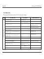
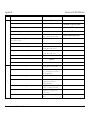
To ease the reader (and ourselves) from the burden of guessing/remembering every single acronym we
have gathered the ones used throughout this thesis in the following table.
Cross-references in the table are in italic (ex: AAL refers to ATM that also as an entry on the table).
AAL
ATM Adaptation Layer
ABR
Available Bit Rate
ACE
Adaptive Communication Environment
ACTS
Advanced Communications Technologies and Services
ANSI
American National Standards Institute
API
ATLANTIC
ATM
Application Program Interface
Advanced Television at Low bit rates And Networked Transmission over Integrated
Communication systems
Asynchronous Transfer Mode
ATMARP
ATM Address Resolution Protocol
BBC
British Broadcasting Corporation
BER
Bit Error Rate
B-ISDN
BSD
BT
Broadband-ISDN
Berkeley Software Distribution
Burst Tolerance
Communications Arch. for Distributed Multimedia Systems
vi
Acronyms
CAC
Connection Admission Control
CBR
Constant Bit Rate
CDV
Cell Delay Variation
CDVT
CDV Tolerance
CLP
Cell Loss Priority
CLR
Cell Loss Ratio
CORBA
CRC
CS
CSELT
Common Object Request Broker Architecture
Cyclic Redundancy Check
Convergence Sub layer
Centro Studi E Laboratori Telecommunicazzioni
CTD
Cell Transfer Delay
CVS
Concurrent Versions System
DCC
Data Country Code
DETAIL
DII
DIMICC
DIMICC Essence Transfer Already Implemented Library
Dynamic Invocation Interface
DIstributed MIddleware for Multimedia Command and Control
DOC
Distributed Object Group
DSI
Dynamic Skeleton Interface
DSM-CC
DVB
vii
III
Digital Store Media – Command and Control
Digital Video Broadcasting
DVB-C
DVB Cable
DVB-S
DVB Satellite
DVB-T
DVB Terrestrial
DVD
Digital Versatile Disk
EBU
European Broadcast Union
EDL
Edit Decision List
EFCI
Explicit Forward Congestion Indication
ENST
Ecole Nationale Supérieure des Télécommunications
EPFL
Ecole Polytechnique Fédérale de Lausanne
ESI
End Station Identifier
FhG
Fraunhofer Gesellschaft
FTP
File Transfer Protocol
HEC
Header Error control Code
Communications Arch. for Distributed Multimedia Systems
III
Acronyms
HTML
Hyper Text Markup Language
I/O
Input/Output
ICD
International Code Designator
IDL
Interface Definition Language
IIOP
Internet Inter-ORB Protocol
INESC
IOR
IP
IPoA
IR
INstituto de Engenharia de Sistemas e Computadores
Interoperable Object Reference
Internet Protocol
IP over ATM
Interface Repository
ISBN
International Standard Book Number
ISDN
Integrated Services Digital Network
ISO
International Standard Organization
IT
Information Technology
ITU-T
International Telecommunication Union Telecommunication standardization
KISS
Keep It Simple Stupid
LAN
Local Area Network
LANE
LAN Emulation
LIS
Logical IP Sub-network
LLC
Logical Link Control
MAC
Media Access Control
MBS
Maximum Burst Size
MCR
Minimum Cell Rate
MOG
Media Objects Group
MPEG
Moving Picture Experts Group
NFS
Network File System
NNI
Network – Network Interface
nrt-VBR
non real time VBR
NSAP
Network Service Access Point
OMG
Object Management Group
ORB
Object Request Broker
ORBIT
OS
Object Reconfigurable Broadcasting using IT
Operating System
Communications Arch. for Distributed Multimedia Systems
viii
Acronyms
OSI
Open System Interconnection
PCR
Peak Cell Rate
PDF
Portable Document Format
PERL
Practical Extraction and Report Language
PES
Packetized Elementary Stream
PMD
Physical Media Dependent
PNNI
Private NNI
POA
Portable Object Adapter
PS
PostScript
QoS
Quality of Service
R&D
Research & Development
RFC
Request For Comments
RSVP
Resource reSerVation Protocol
RTF
rt-VBR
Rich Text Format
real time VBR
SAP
Service Access Point
SAR
Segmentation And Reassembly
SCR
Sustainable Cell Rate
SDI
Serial Digital Interface
SDK
Software Development Kit
SDU
Service Data Unit
SEL
SELector
SMPTE
Society of Motion Pictures and Television Engineers
SNAP
Standard Network Access Protocol
SPTS
Single Program Transport Stream
TAO
The ACE ORB
TC
ix
III
Transport Convergence
TCP
Transmission Control Protocol
TLI
Transport Layer Interface
TM
Trade Mark
TS
Transport Stream
TV
TeleVision
TVI
TeleVisão Independente
Communications Arch. for Distributed Multimedia Systems
III
Acronyms
UBR
Unspecified Bit Rate
UMID
Universal Material IDentifier
UML
Unified Modelling Language
UNI
User – Network Interface
UPC
Usage Parameter Control
VBR
Variable Bit Rate
VC
Virtual Channel/Connection
VCI
VC Identifier
VIP
Very Important Person
VP
Virtual Path
VPI
VP Identifier
VTR
Video Tape Recorder
WAN
Wide Area Network
WIP
Work In Progress
WS
WorkStation
XP
eXtreme Programming
Communications Arch. for Distributed Multimedia Systems
x
Acronyms
xi
III
Communications Arch. for Distributed Multimedia Systems
IV
Contents
IV.
I.
Contents
Abstract ___________________________________________________________________________________ ii
Resumo ______________________________________________________________________________________ iii
II.
Acknowledgements__________________________________________________________________________iv
III. Acronyms _________________________________________________________________________________vi
IV. Contents _________________________________________________________________________________ xii
V.
List of Figures ____________________________________________________________________________xvi
1. Introduction _________________________________________________________________________________ 2
1.1. Goals ____________________________________________________________________________________3
1.2. Text Organization__________________________________________________________________________4
1.3. Notation used _____________________________________________________________________________4
2. Related Projects ______________________________________________________________________________ 6
2.1. TV – the box that is being changed by the world_________________________________________________6
2.1.1. Are we digital yet? ______________________________________________________________________7
2.1.2. But why go digital? ______________________________________________________________________8
2.2. The need for ATM _________________________________________________________________________9
2.3. ATLANTIC______________________________________________________________________________10
2.3.1. Control_______________________________________________________________________________11
2.4. ORBIT __________________________________________________________________________________12
2.4.1. Reference model _______________________________________________________________________13
2.4.2. Phase 2 – Getting the show on the Television Studios __________________________________________15
3. Technologies Description ______________________________________________________________________ 16
3.1. ATM and QoS____________________________________________________________________________16
3.1.1. ATM Adaptation Layers (AALs) __________________________________________________________18
3.1.2. Service Categories and QoS ______________________________________________________________19
3.1.3. ATM addressing _______________________________________________________________________22
3.1.4. CLIP and LANE _______________________________________________________________________23
3.1.5. Windows API _________________________________________________________________________24
3.1.6. ATM on Linux_________________________________________________________________________24
3.1.7. Conclusion____________________________________________________________________________25
Communications Arch. for Distributed Multimedia Systems
xii
Contents
IV
3.2. CORBA ________________________________________________________________________________
3.2.1. Brief comments on IDL_________________________________________________________________
3.2.2. The ORB ____________________________________________________________________________
3.2.3. Method invocation_____________________________________________________________________
3.2.4. CORBA Services______________________________________________________________________
3.2.4.1. Naming Service ___________________________________________________________________
3.2.4.2. Trading service ____________________________________________________________________
3.2.4.3. Event and Notification Service ________________________________________________________
3.2.4.4. Property Service ___________________________________________________________________
3.2.5. Final Notes __________________________________________________________________________
25
26
27
28
29
29
29
30
30
30
4. Programming Environment ____________________________________________________________________ 32
4.1. ACE ___________________________________________________________________________________
4.1.1. Reactor______________________________________________________________________________
4.1.2. Acceptor - Connector Pattern ____________________________________________________________
4.1.3. Stream Architecture____________________________________________________________________
4.1.4. Service Configurator ___________________________________________________________________
4.1.5. Existing ATM support __________________________________________________________________
32
34
36
38
40
42
4.2. The ACE ORB (TAO TM) __________________________________________________________________ 42
4.3. DIMICC version 1 _______________________________________________________________________ 44
4.4. DETAIL and DIMICC-2 __________________________________________________________________ 47
4.5. Other used tools _________________________________________________________________________
4.5.1. Bugzilla _____________________________________________________________________________
4.5.2. CVS (Concurrent Versions System) _______________________________________________________
4.5.3. Doxygen ____________________________________________________________________________
52
52
53
54
5. Development/Integration and Test_______________________________________________________________ 56
5.1. ATM Development _______________________________________________________________________ 56
5.1.1. ATM classes for ACE __________________________________________________________________ 57
5.1.1.1. Defined classes ____________________________________________________________________ 58
5.1.1.1.1. Connection ID _________________________________________________________________ 59
5.1.1.1.2. The binding to the 0 port of the SOCK world _________________________________________ 60
5.1.1.1.3. Getting the peer name ___________________________________________________________ 61
5.1.1.1.4. Functions not implement and why__________________________________________________ 62
5.1.1.2. QoS enabling _____________________________________________________________________ 63
5.1.1.3. Some words about the Windows implementation _________________________________________ 64
5.1.1.4. Other words about the Linux Implementation ____________________________________________ 65
5.1.1.5. Integration in the ACE framework _____________________________________________________ 65
5.1.2. Integration of ATM classes in DIMICC’s 1 st version __________________________________________ 65
5.1.3. ATM integration in DETAIL ____________________________________________________________ 67
5.1.3.1. Defining the ATM module to be insert into the ACE Stream_________________________________ 70
5.1.3.2. Integration________________________________________________________________________ 71
5.1.3.3. Integration in DIMICC’s 2 st version ____________________________________________________ 72
5.2. Testing the source code ___________________________________________________________________
5.2.1. Test of each functionality _______________________________________________________________
5.2.2. Extreme Programming Testing ___________________________________________________________
5.2.3. Conclusion___________________________________________________________________________
72
73
73
75
6. Concluding Remarks _________________________________________________________________________ 76
6.1. Work Conclusions _______________________________________________________________________ 76
6.1.1. Conclusions drawn ____________________________________________________________________ 76
6.1.2. Industry results _______________________________________________________________________ 77
6.2. Personal Gains __________________________________________________________________________ 79
6.3. Topics needing further development ________________________________________________________ 79
7. Bibliography ________________________________________________________________________________ 82
xiii
Communications Arch. for Distributed Multimedia Systems
IV
Contents
7.1. Languages related (CORBA, UML, C++, ACE) ________________________________________________82
7.1.1. Books________________________________________________________________________________82
7.1.2. Standards _____________________________________________________________________________82
7.1.3. Papers _______________________________________________________________________________83
7.1.4. Hyperlinks ____________________________________________________________________________83
7.2. Patterns _________________________________________________________________________________84
7.2.1. Books________________________________________________________________________________84
7.2.2. Papers _______________________________________________________________________________84
7.2.3. Hyperlinks ____________________________________________________________________________84
7.3. ATM____________________________________________________________________________________84
7.3.1. Books________________________________________________________________________________84
7.3.2. Standards _____________________________________________________________________________84
7.3.3. Manuals ______________________________________________________________________________85
7.3.4. Papers _______________________________________________________________________________85
7.3.5. Hyperlinks ____________________________________________________________________________85
7.3.6. Thesis _______________________________________________________________________________85
7.4. Others (ATLANTIC, ORBIT, Video, XP, OMG, Tools) _________________________________________85
7.4.1. Papers _______________________________________________________________________________85
7.4.2. Thesis _______________________________________________________________________________86
7.4.3. Hyperlinks ____________________________________________________________________________86
8. Index ______________________________________________________________________________________ 88
Appendix - A Usage of the ACE ATM classes________________________________________________________ 92
A-1. Windows________________________________________________________________________________92
A-2. Linux __________________________________________________________________________________92
Appendix - B Functions of the ACE ATM classes ____________________________________________________ 94
B-1. Stream Class ____________________________________________________________________________94
B-2. Acceptor Class ___________________________________________________________________________97
B-3. Connector Class_________________________________________________________________________100
B-4. Address Class___________________________________________________________________________103
Appendix - C IDL for the ATM usage in DIMICC ___________________________________________________ 106
C-1. DIMICC Version-1 ______________________________________________________________________106
C-2. DIMICC Version-2 ______________________________________________________________________107
Appendix - D UML Notation used ________________________________________________________________ 110
Communications Arch. for Distributed Multimedia Systems
xiv
Contents
xv
IV
Communications Arch. for Distributed Multimedia Systems
V
V.
List of Figures
List of Figures
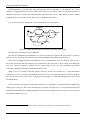
Fig. 2-1 - ATLANTIC studio Reference Model (from [43])................................................................................................11
Fig. 2-2 – ORBIT reference model (from [45])..................................................................................................................13
Fig. 3-1 – Data travel in ATM (from [26]).........................................................................................................................17
Fig. 3-2 – ATM layers ........................................................................................................................................................18
Fig. 3-3 – NSAP structure ..................................................................................................................................................23
Fig. 3-4 –The structure of the ORB Interface (from [3]) ...................................................................................................27
Fig. 3-5 – Method Invocation in same ORB and crossing ORBs (from [19]) ....................................................................28
Fig. 4-1 – ACE key components (from [16]) ......................................................................................................................34
Fig. 4-2 – Reactor Components (from [23]) ......................................................................................................................35
Fig. 4-3 – Acceptor-Connector relations (adapted from [24]) ..........................................................................................37
Fig. 4-4 – Stream Components (adapted from [11])..........................................................................................................38
Fig. 4-5 – Synchronous and Asynchronous behaviour in Streams (from [11])..................................................................40
Fig. 4-6 – State diagram of the service Life Cycle (from [10]) ..........................................................................................41
Fig. 4-7 – TAO block diagram (from [17]) ........................................................................................................................43
Fig. 4-8 – Control Plane Simplified Architecture ..............................................................................................................45
Fig. 4-9 – Essence Transfer Protocol Stack (from [42])....................................................................................................45
Fig. 4-10 – Connection Managers in the Component ........................................................................................................46
Fig. 4-11 – DIMICC-2/DETAIL transport architecture.....................................................................................................48
Fig. 4-12 – Sequence Diagram for SourceóSink Creation and Connection.....................................................................49
Fig. 4-13 – Creation of the Stream in the Source/Connecting Side....................................................................................50
Fig. 4-14 – Creation of the Stream in the Sink/Accepting Side ..........................................................................................51
Fig. 5-1 – Inheritance tree of ACE SOCK classes..............................................................................................................57
Fig. 5-2 – Inheritance tree of ACE ATM classes................................................................................................................57
Fig. 5-3 – Inheritance tree for DIMICC ATM classes........................................................................................................66
Fig. 5-4 –DIMICC ATM classes relationship ....................................................................................................................67
Fig. 5-5 – ATM Stream Connection establishment in DETAIL ..........................................................................................68
Fig. 5-6 – ATM Stream Connection Acception in DETAIL ................................................................................................69
Fig. 5-7 – Creation of ConnectionModule from ATMConnectionTasks.............................................................................69
Fig. 5-8 – Abstraction of some Stream classes...................................................................................................................71
Fig. 5-9 – ATM Stream Module inheritance.......................................................................................................................72
Fig. 8-1 – UML class examples........................................................................................................................................110
Fig. 8-2 –UML Relation examples ...................................................................................................................................111
Fig. 8-3 – Use case example ............................................................................................................................................112
Communications Arch. for Distributed Multimedia Systems
xvi
1
Introduction
1.
Introduction
"When we walk to the edge of all the light we have,
And take that step into the darkness of the unknown,
We must believe that one of two things will happen ...
There will be something solid for us to stand on.
Or, we will be taught to fly. "
-- Zen Proverb
In this first chapter, we will introduce the objectives of this thesis. We will
state the reasons that led us to develop this work and the methodology
used. The technologies involved will be referred to in the process. The
reader will also be introduced to the notation used throughout the text.
When the work illustrated in this thesis began, ATM (Asynchronous Transfer Mode) was already making
a stand in the local network. There was some research to provide the industry with feasible solutions, based
on ATM with ATM Forum leading the standardization process. The market was also responding well to
ATM. There was the desire to pick up this technology used primarily in backbones and take its unique
strengths to the end-user environment.
Already with a strong position in the market was Fast Ethernet (although with lower throughput). Gigabit
Ethernet caught up ATM when ATM was establishing itself in the LAN (Local Area Network) environment.
Here started a competition for the LAN segment, with (at the time) ATM leading the way in QoS (Quality of
Service) related applications, because the Ethernet technologies lacked the QoS capabilities and bandwidth
reservation of ATM. ATM also had a higher throughput than Fast Ethernet and Gigabit was not yet available
for LAN use. Therefore, Ethernet features seemed less appealing than those of ATM. Hence, research
Communications Arch. for Distributed Multimedia Systems
2
Introduction
1
departments started to develop and exploit software that could embrace this new technology (at least for the
local network) and make full use of its advantages.
TV (TeleVision) industry was one of the interested partners in this research.
TV was starting to move to the digital world in the studio production area. They used different work tools
from different manufacturers into the working place, and had to make ends meet in order to integrate the
different materials. Their costs were quite high, because they had to use proprietary and extremely high
quality hardware in the production and broadcast areas. They wanted/required to join the low cost
information technology world without losing their high quality standards.
This situation led to the birth of projects that aimed to reduce TV studio production costs. In the process,
TV operators also wanted to increase production speed, to improve the workflow process, make possible
production in different media types and to achieve greater flexibility in production.
ATM was selected as an important component of these projects, as the underlying network infrastructure
that connected all the resources, transporting data and commands to the work tools in a reliable and
guaranteed way.
1.1. Goals
The scenario portrayed describes the motivation for the work in this thesis. TV studios were eager to enter
the digital arena and to adopt IT (Information Technology) solutions that would lower costs and improve
production quality and flexibility. Projects were developed to achieve this goal, but the stakes kept growing
higher with the success of the projects. Distributed access and control of the material (content) was thought
of, different network technologies needed to be addressed, new video formats had to be dealt with and new
information related to the material (metadata) should be transported with it.
These aspects traverse several technical areas. In this thesis, we will stick to the network aspects. Our
main goals will be:
· To provide the network infrastructure of the project with the means to use ATM as a transport
technology.
· To contribute to the integration of different network technologies in the infrastructure.
· To prove the feasibility of using ATM in the TV studio network and therefore prove that ATM can
reach the end-user.
To this end, we will use programming technologies that (as we will describe) are best fitted to the
challenge at hand. C++ and CORBA (Common Object Request Broker Architecture) will be the primary
programming environment. We will use a framework developed with communication principles in mind
3
1.1 Goals
1
Introduction
named ACE (Adaptive Communication Environment). The technology already developed for the projects
will be adapted to support ATM.
This development will imply the study of ATM characteristics and its implementation details in the
operating systems to be used. CORBA and its services will also have to be dealt with. Language patterns will
be widely used as an aid to better develop code. To test the software built, we will try to use the best test
practices. Other tools will also be used to manage a project of this dimension.
1.2. Text Organization
Throughout this text, we will try to follow more or less the same path that we employed during our work.
The effort will be (as in every thesis) to introduce the reader to the theory behind the practice before
describing the actual development made.
To start out, we will try to answer the “why do it?” question. Therefore, in chapter two we will try to
explain the motivation behind this work. The TV studio hunger for digital means (that we mentioned earlier)
will be described here. The use of ATM technology in this environment will be discussed in this chapter. The
projects where this work started and in which we dwell ourselves are also addressed in this section.
In chapter three, the going gets tougher and so we will get going to the more technical aspects, elaborating
through the technologies used. We will portray the network infrastructure to be used, ATM and see an overall
picture of CORBA. This section will serve to describe the theory behind our work.
The number 4 will lead us to the description of the ACE communication framework (which we mentioned
in the previous sub-section). The architectures developed in the projects described in chapter two will be
more thoroughly analysed here, including the programming infrastructure where the work was done, and on
which some improvements were made.
The fifth chapter will show the ‘real deal’. The development that was the purpose of this thesis will be
described, as well as the use and testing of the mechanisms implemented.
The final chapter (number six) aims at drawing conclusions of the work undertaken. It also tries to
discover new paths to follow. Not all statements proved to be true, and being able to conclude that the path to
be taken will not be the one we draw is not an easy achievement. In this chapter, we will develop on this
puzzling initial remark of a thesis and try to see ahead on our crystal ball.
1.3. Notation used
We will be using different font types to emphasize some aspects.
The default font will be Times New Roman, which is employed in the normal text.
Courier New will be applied to:
Communications Arch. for Distributed Multimedia Systems
4
Introduction
1
o
Code fragments or references to classes
o
File paths
o
System variables
Some sentences or expressions will be ‘quoted and in italic’. This will refer to:
o
‘Foreign’ expressions
o
‘Cute, humorous expressions’ (not many, and not that humorous)
Acronyms will be widely used in the entire document. When a new one is introduced, its meaning will be
revealed; however, in the following appearances the user is referred to section III if in doubt of its
significance.
Bibliographic references will appear with the formal style, which is between parentheses. This will only
apply to the bibliography that was read or consulted during the course of this work. Some direct references
will appear in the text when their content was of minor significance to the thesis, but may nonetheless interest
the reader.
UML (Unified Modelling Language) is largely used throughout the document, especially in the more
technical chapters. A small appendix explaining some of concepts UML is in Appendix - D. The reader
should consult/read it if uncertain of some notation used.
5
1.3 Notation used
2
Related Projects
2.
Related Projects
"By three methods we may learn wisdom:
First, by reflection, which is noblest;
second, by imitation, which is easiest;
and third by experience, which is the bitterest."
-- Confucius
It is the need that drives the man further in the paths of knowledge. In this
chapter, we will describe the necessity that drove the projects from
which this thesis was born. For that purpose, we will talk about
video/audio digital formats and their use in a TV studio. We will then
describe the projects and the current state of them. We will see what are
their goals in the pursue of filling the industry needs. The ORBIT project will
be looked upon with more detail, as it is where the work described here
dwells. The specific architecture of ORBIT will be the subject of a later
chapter.
2.1. TV – the box that is being changed by the world
The motivation for this thesis came from the new challenges in television production studios. The world is
asking more out of the ‘box’ and this led to the project where our work ‘lived’.
The thesis will explore some aspects of digital television, but will stray to more specific work, which
although related to the project, is more concerned with network specific issues. Nonetheless, we will try to
introduce the concepts that drove the project in the next sub-chapters.
Communications Arch. for Distributed Multimedia Systems
6
Related Projects
2
2.1.1. Are we digital yet?
As one reads through the bibliography (namely [51] and [52]) to get a better knowledge about the studio
production arena, a doubt starts to grow: is the TV production studio still in the pre-digital age as argued in
[51] and [52]? The answer is not an easy one.
The world all around is becoming digital. When we think of DVD (Digital Versatile Disk), pay-per-view,
video on demand it is hard not to think in terms of bits. Digital TV broadcasting is also formed by bytes (if
for no other reason, it must ensure the digital services to the consumers); we have DVB with an S for satellite,
with a C for cable and with a T for terrestrial. All are Digital Video Broadcasting. This is not true for all the
countries (including Portugal, which has only some field trials 1), but there is a wider coverage than in the
past. Consumers are also picking up the pace, because in the final run they are setting it.
Photography is surely going digital (if it is not already). Digital cameras are of common usage in our days.
Using compression and digital memory based systems, they are surely away from the analogue past.
Although disk based video cameras are not widespread, there begins to be a market for the manufacturers to
explore.
The Internet is not even worth mentioning, because it is an implanted fact in everyone’s life. Interactivity
and digital availability of contents are of course a must in the ‘net’.
TV studios have embarked in all these developments, Internet being the most easily recognizable one
(almost every TV studio is connected and broadcasts news online). However, we are running from the real
question: how is the TV studio production?
We are not referring to the spectacular special effects seen in the movies (the stand-on that does not look
very good in the framing and is therefore digitally erased). There is no doubt that movie studio production has
embraced digital content2. One could argue that if the movies have it, surely the TVs should also use it.
However, one has only to be reminded of a daily production of a news program (handling last minute footage,
resorting to archives to better cover a story), with its different profit values to think twice about digital. The
program production equipment used is fairly closed and proprietary, leading to high prices. If those means
were deployed in TV production studios, they would be less cost-effective than in movie studios. Of course,
there are exceptions, but the overall picture seems to be a struggle to get to digital but without ‘ selling their
pants’ in the process.
The conclusion seems to be that, TV operators are eager to have fully digital production studios, some
already use mostly digital formats in their processes. There is not however a cost-effective solution to put all
1
Two noble Portuguese exceptions are one cable operator (TVCabo from Portugal Telecom) and a private generalist
channel (TVI (TeleVisão Independente)), which both provide some interactive emissions.
2
Although one could argue that, the costs of this embracement are similar to those of TV studios, they are nonetheless
much more profitable.
7
2.1 TV – the box that is being changed by the world
2
Related Projects
production staff to watch only bits pass by. Here we touch another sensitive point: the people are only now
getting acquainted with digital means, and have the normal resilience to change to new processes.
Summing up, we have passed the pre-digital era, but are on the transition period, not in the final age.
2.1.2. But why go digital?
We never said why it was good to go digital. In these days, it seems a strange question to put, but we will
try to point out the facts regarding the TV production studio.
There is no doubt that digital transport can convey more and better information, adding also more
flexibility. It can be compressed and it is less susceptible to errors due to the medium. This allows the
transport of higher quality video/audio. Therefore, a known primary feature is the excellence of the data
transported; it is a ‘better’ data.
Therefore, this leads to a reduced bit rate in data related to image and sound, so there is bandwidth that can
be used to transfer other information. We can add more video/audio to the data. We can transport different
views for the video or different languages for the audio. Different angles of the same event give the user the
freedom of choosing the detail he wants to see.
There is however another more interesting use of this ‘surplus’ bandwidth; the end user can receive
ancillary data. Data about the data or metadata as the EBU (European Broadcast Union) and the SMPTE
(Society of Motion Pictures and Television Engineers) named it. This is new information available not only
to the end user, but also to the people handling the programs. They now can query the system about attributes
of the video/audio they are using. The end-user can know who made the documentary, when was it recorded,
etc. The responsible for editing the program can identify the location of the footage for subtitling, the quantity
of light during the filming, etc. Copyrights can be added. This has a wide range of use.
The video and audio information had to be called something different from data 1, so EBU/SMPTE named
it essence2. The information transported is now the combination of essence and metadata, and is named
content. Content is therefore the high coupling of essence and metadata.
Other advantage of the digital medium is storage and access. [51] and [52] presented a workflow for the
TV production studio (back in 2000) with several points of failure and introduced delays. The main issue was
the need for organization to keep the material (videotapes or their copies) traceable, i.e., to know their current
location and the transportation of the material. The different formats available for the stored material would
also prove to be a loss of time to the editor wanting to use archived footage.
1
2
This has either a very broad meaning (related to any type of information) or a specific use (e.g., computer data).
This also includes graphics information, subtitles, etc.
Communications Arch. for Distributed Multimedia Systems
8
Related Projects
2
The characteristics of the digital medium can ease these problems. The material (essence) is not physically
manipulated, so there is no fear of getting it lost. This way it is also always traceable and easier to copy as it
shares a single format or is easily transformed from one to another. The metadata can ease the ‘hunt’ for those
special scenes, since it is highly coupled with the essence.
In conclusion, TV needs to get digital in the production arena and projects like the ones described next can
help to reach these goals.
2.2. The need for ATM
In [46] we can read an interesting question “what could be the role of networking in this evolving scenario
[introduction of MPEG-2 in TV studios], or even strongly, is there a single network technology suitable for
the whole broadcasting environment?”. The authors then suggested ATM.
TV studios already had a media transport SDI (Serial Digital Interface). This technology transported
uncompressed digital video at a rate of up to 270 Mbps. However, this option had some drawbacks. The use
of an uncompressed signal was the first one. Higher rates were being required and SDI would not accomplish
that request, due to the transport of uncompressed signals. The second was cost, since these solutions were
very expensive. It also required tight synchronization between systems, which led to some compromises and
high costs to achieve it.
The use of compressed MPEG-2 (Moving Picture Experts Group) allowed the use of other types of
network technologies. ATM was the preferred one in the projects we will describe, as it was the available
technology that could fulfil the requirements identified. ATM will deserve a deeper look in 3.1, but we will
now resume some of its advantages in TV studios networks.
ATM was proclaimed not to provide reliable delivery, which in real time systems (like video
broadcasting) would undermine its QoS capabilities. Cells are dropped in ATM if errors arise 1, and
retransmission is not an option in real time systems. However, in long hauls BER (Bit Error Rate) as low as
10-12 could be obtained. As we will see, the CLR (Cell Loss Ratio) is the factor in ATM that measures the
losing of cells (due to either errors or congestion in the network). CLR of 2 x 10-11 were typical, and could be
improved with forward error correction. Therefore, this fear was not well placed, as long as the correct traffic
parameters were chosen. The CBR (Constant Bit Rate) and rt-VBR (real time VBR (Variable Bit Rate))
categories of service (see 3.1.2 for further details) were the most adequate to the job at hand.
Other strong points are:
· Wide support from the industry, which led to cost-effective solutions.
· Scalability in speed (e.g., 2, 25.6, 100, 155, 622 Mbps) and distance.
1
9
And also if congestion or delays happen (but this is subject to the Service Category being used, see 3.1.2).
2.2 The need for ATM
2
Related Projects
· Ability of providing bandwidth on demand (CBR for example guarantees a constant cell rate during
the entire connection).
· Capacity of setting QoS parameters per virtual circuit flow.
The above reasons made ATM a serious competitor in the network area. It also impelled the work done in
this thesis.
2.3. ATLANTIC
As we have seen, it was a growing necessity to lead the digital environment (and its compression
techniques) to the edition/production area of a TV studio. In an effort to handle these issues the ATLANTIC
(Advanced Television at Low bit rates And Networked Transmission over Integrated Communication
systems) project [43][44][53] was started in the beginning of 1995. The project was funded by the European
Community, under the ACTS (Advanced Communications Technologies and Services) program, and was
integrated by BBC (British Broadcasting Corporation) R&D (Research & Development), CSELT (Centro
Studi E Laboratori Telecommunicazzioni), ENST (Ecole Nationale Supérieure des Télécommunications),
EPFL (Ecole Polytechnique Fédérale de Lausanne), FhG (Fraunhofer Gesellschaft), INESC (INstituto de
Engenharia de Sistemas e Computadores) and Snell & Wilcox. The goal of the project was to convey MPEG2 format through the entire chain in a TV studio production environment.
The aim was to reduce the loss of quality due to the successive decoding/coding operations done on the
essence, trough the production chain, from the input of the studio to final programme distribution. A new
technology was developed to improve the recoding process. The MOLE TM system added to the decoded
signal information about how the signal was previously coded. After the decoded signal had been processed,
this knowledge was used in the following MOLE encoder to produce an optimal encoded signal.
The studio network was based on ATM technology. The characteristics of ATM (that we will discuss
later) like flexibility, scalability, support for QoS requirements, etc, led to its choice. However, there was the
need to deliver reliably the MPEG-2 streams, so another protocol layer was required. TCP (Transmission
Control Protocol) met the requirements, and so Classical IP (Internet Protocol) over ATM was used in spite
of its limitations (see further in 3.1.4), which were overcome in the studio environment.
ATLANTIC also had the goal of proving the possibility of using inexpensive IT technology to substitute
the specialised equipment typically used in the studios. To demonstrate this assessment, a news studio was
developed using low price computers, with the higher costs going to the ATM network 1 and video cards
needed. Nonetheless, it was a much lighter investment than the usual proprietary equipment of news studios,
which normally used dedicated proprietary hardware to do the tasks that now were to be handled by IT
technology.
1
Even so, ATM was a cheaper investment than the high quality digital interfaces, mentioned earlier.
Communications Arch. for Distributed Multimedia Systems
10
Related Projects
2
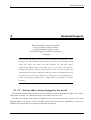
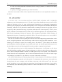
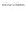
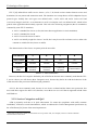
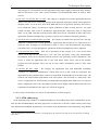
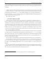
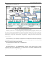
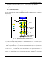
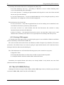
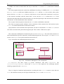
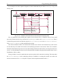
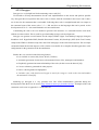
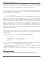
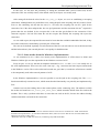
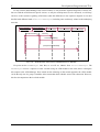
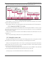
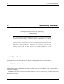
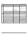
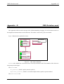
The reference model used (taken from [43]) is illustrated in Fig. 2-1 (a brief discussion of each component
follows).
Edit WS
Server
Format
Converter
MPEG2
SPTS
ATM
network
Browse Track
generator
finished programme
TS server
Edit Conformer
(real-time bit stream
switch and multiplexer)
Fig. 2-1 - ATLANTIC studio Reference Model (from [43])
The Format Converter is the entry point of data to the ATLANTIC network. It receives MPEG-2 SPTS
(Single Program Transport Streams) and converts them in PES (Packetized Elementary Streams), recovering
in that way all elementary components. The PES are then stored in a Server. The Server also keeps index files
related to PES, to ease the conversion of timestamps to byte offsets 1.
The Edit WorkStation will allow the creation of programmes (video sequences) in the form of EDL (Edit
Decision Lists). An EDL consists of the description of the glued pieces of video/audio that will make a
program. It is a description of the edits. The station consists of a GUI and MPEG-2 commercial decoder
boards. In the Edit WorkStation there is also the possibility of previewing the programme in lower quality
format (browse quality or MPEG-1 I-frame only). This introduces the next component that generates this
browse quality streams, the Browse Track Generator. It transforms MPEG-2 streams into MPEG-1 I-frame
and stores them in the Server. Indexes are also generated to relate the browse quality streams to the fullquality ‘parents’.
The Edit Conformer takes the EDL produced in the Edit WorkStation and generates the final programme
in MPEG-2 format. It then stores it in the Finished Programme Transport Stream Server.
2.3.1. Control
The various pieces in the ATLANTIC environment needed to be controlled. There were different
approaches to handle this issue. It started with operating system native tools (remote logins, NFS (Network
File System), FTP (File Transfer Protocol)). Soon it proved difficult to manage the situation and they evolved
to DSM – CC [49] (Digital Store Media – Command and Control), which was initially specified for video on
1
This enables random, time –based access to the streams.
11
2.3 ATLANTIC
2
Related Projects
demand services, which had some common requirements to those found on a production studio environment.
This also revealed to be an inappropriate control mechanism.
After this point, the ATLANTIC team started to develop their control framework. First a solution based on
DSM-CC (Digital Store Media – Command and Control) was developed. Nonetheless, some of the former
inadequacies surfed up. Therefore, the decision to start a new solution from scratch was taken, and this led to
DIMICC (DIstributed Middleware for Multimedia Command and Control). The work of this dissertation is
based on it, and so we will describe it in 4.3.
This project lasted more than three years and achieved most of its objectives.
2.4. ORBIT
ATLANTIC showed a new road to take. The project demonstrated that it was possible to handle the
production requirements of a TV studio using low cost IT solutions/systems.
The BBC R&D decided to follow that road. Together with INESC Porto they decided to launch the
ORBIT (Object Reconfigurable Broadcasting using IT) project [45][54].
In its starting phase, ORBIT intended to develop a pilot implementation of the concepts of ATLANTIC.
This demonstrator would be a small-scale production area, with the following aspects in mind (from [45]):
· Use of IT hardware to deal with essence (video/audio contents) and metadata, replacing expensive
proprietary hardware.
· Interconnection of media asset management and content handling tools.
· Easy access from the desktop to the different contents.
· Flexibility to handle diverse formats and any necessary conversion.
· Easy reconfiguration to cope with various production processes and programme genres.
ORBIT also aimed at providing input into the standards organizations (like the Pro-MPEG Forum),
regarding the techniques developed during ATLANTIC. The project also ‘carried’ the middleware ‘flag’,
proclaiming it as a flexible and scalable solution in TV studios. In this way, it meant to transfer to the
industry the technology developed in ATLANTIC.
A new item was added in ORBIT: data about the data, i.e., metadata. The need to know various attributes
about the captured material was now of importance. To handle data about the type of camera used in the
shooting, the name of the VIP (Very Important Person) talking in a specific scene or the owner of the rights
of the film, there is a need of automatic and manual annotation of the essence. This information must be
closely coupled with video/audio with which it is related. This was another challenge in ORBIT, move from
Communications Arch. for Distributed Multimedia Systems
12
Related Projects
2
the ‘writings on the tape’ to the database that stored the data about the data and give easy access to it, in order
to do searches on it or retrieve it easily for broadcasting along with the essence.
At the time, there was already some database handling of metadata. However, at that point, the deployed
systems created islands by separating metadata from the essence it was related to. The main reason was the
different worlds where the companies that dealt with the essence and the ones that handled metadata lived in.
They were far apart and led to implementations being also away from each other. The lack of standards that
allowed a more close relation between these two also helped to worsen this problem. However, the standards
bodies (EBU/SMPTE) were releasing the rules that would allow the treatment of content.
At this point, it is worth reminding that content equals essence plus metadata. ‘The word on the street’ is
now content and not only the video/audio essence.
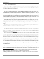
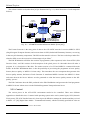
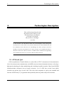
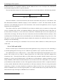
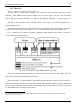
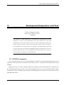
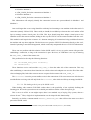
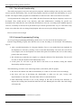
2.4.1. Reference model
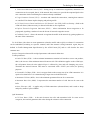
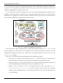
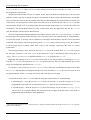
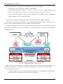
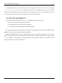
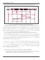
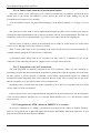
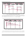
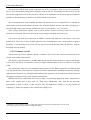
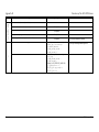
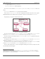
The initial ATLANTIC model grew, and new features were added to prove the concepts, as we can see in
Fig. 2-2.
Fig. 2-2 – ORBIT reference model (from [45])
Now we had different and slightly separated areas with a sort of gateways guarding the access to each
other. We can see the different productions studios (for news, wildlife programs, etc), an archive area where
all productions could/should resort in order to find related footage and a play out area.
The gateway services were devised to provide:
· An aggregated view of the other areas, giving a single point of access to other systems.
13
2.4 ORBIT
2
Related Projects
· The ability to copy content from one area to another, giving new unique identifications to the copied
material.
· Control of who is accessing what, i.e., security measures.
As we can see, there is more to the gateway than meets the word.
However, the focus on this primary stage was in creating one working production area.
The various items were:
· Intake hosts – they are the start of the digital chain; capable of capturing essence at full and browse
quality (as referred to in ATLANTIC) from VTRs (Video Tape Recorder), cameras or live feed,
these machines were controlled by the client workstations (including start, stop, pause, go to
timestamp X (in the case of a VTR)). The output of these elements was directed to the content
servers.
· Content Servers – although referring to content, these servers only kept essence. The browse and
full quality data extracted from the intake hosts was ‘dumped’ here. These servers also allowed
access to the essence, be it the browse quality for edition or the full quality for final programme
production.
· Metadata Database – as mentioned this was an important component. The intake hosts
automatically extracted some metadata; other was inserted in annotation stations (portrayed in Fig.
2-2 as part of the client workstations). This metadata was, of course, searchable in order to access
the needed essence.
· Editor – in this workstation, simple edits could be made to create the EDL for a programme. As
mentioned the editor uses browse quality format to compile these lists.
· Quality Monitoring Host – these machines allowed the quality control of final programmes, as they
streamed the essence from the content servers and displayed it in broadcast quality monitors and
loudspeakers for approval.
· Processing Servers – they process the EDL generating the final programmes and enabling them to
the play out area.
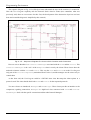
The task was not only to create these services, but also to command and control them in a distributed way
over the local network area (and beyond).
With this prototype, the group could receive comments and critics from the operational staff. This
feedback is critical in any software development.
This first phase was achieved successfully and new chapter arose.
Communications Arch. for Distributed Multimedia Systems
14
Related Projects
2
2.4.2. Phase 2 – Getting the show on the Television Studios
The first trial was a proof of concept of the ATLANTIC ideas with a added functionality. This
confirmation made the interest in the project grow, and some specific departments of the BBC started to show
commercial interest in the soon to be product. Therefore, the next step was to make it a real, fully tested and
(why not say it) a commercially viable solution to television studios.
This phase led to engaging in a development more out of the academic world and more into the industry
habits. New quality assurances were asked for; better proofs of the functionalities were needed;
documentation and maintenance were of higher importance. This obliged to the enforcement of industry
standards on software development techniques.
This is the WIP.
15
2.4 ORBIT
3
Technologies Description
3.
Technologies Description
“The world is formed from the void
like utensils from a block of wood.
The Master knows the utensils,
yet it keeps to the block:
thus she can use all things”
-- Lao Tzu
In this section, we will delve inside the technologies used during the
development of this thesis. The network infrastructure and middleware will
be addressed. We will start out describing the ATM concepts and the
Quality of Service associated to it. Some words on its implementation in
Windows and Linux will be written. CORBA will be addressed regarding
the middleware section. Its services will be briefly referred.
3.1. ATM and QoS
ATM (Asynchronous Transfer Mode) is a joint effort of ITU-T (International Telecommunication
Union Telecommunication standardization) and ANSI (American National Standards Institute ) to develop a
high-speed technology for data multiplexing and switching in public networks. Born from B-ISDN
(Broadband-ISDN (Integrated Services Digital Network)), use of ATM has evolved from public
networks into private ones (in the LAN). This led several companies to pick up the standard and
form the ATM Forum [37] to guarantee interoperability between public and private networks.
Communications Arch. for Distributed Multimedia Systems
16
Technologies Description
3
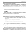
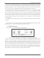
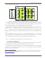
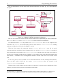
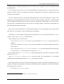
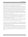
ATM uses small sized cells to transport data (5 bytes of header + 48 bytes of payload). This allows fast
switching operations, leading to high-speed transfer.
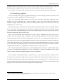
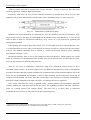
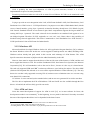
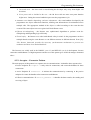
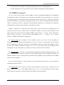
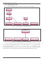
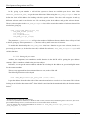
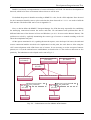
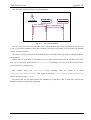
Essentially ATM relies on VCs (Virtual Channel/Connection) to transport data. These VCs are then
bundled in VPs (Virtual Paths) that traverse the media. This is illustrated on Fig. 3-1 taken from [26].
Fig. 3-1 – Data travel in ATM (from [26])
Identifiers for virtual connections are structured into VCI (VC Identifier) and VPI (VP Identifier). VCIs
range from 0 to 65535. The range of VPIs depends on the interface being used; therefore, it is 0-255 in UNI
and 0 to 4096 in NNI (we will describe both next). VCIs from 0 to 31 are reserved for signalling and
management operations.
UNI signalling for example is done using VPI=0, VCI=5. UNI stands for User to Network Interface. This
is a connection between a user and a private network or between a switch in a private network and a public
network. The standard signalling used is defined in “ATM User-Network Interface (UNI) Signalling
Specification Version 4.1” [28].
Besides this interface, there is also a NNI (Network-to-Network Interface), which connects two switch
nodes in a network (or in different networks). If in the same private network, they use PNNI (Private NNI),
but it can also connect two different public networks.
There are two ways of establishing a connection, using PVCs (Permanent Virtual Circuit) or SVCs
(Switched Virtual Circuits). As the name implies PVCs are defined on the network by means of management
procedures and the connection remains established for a contractual period until manual teardown. This is the
down size, the establishment and teardown of PVCs is done manually and all connections (traversing all
switches) must be defined. Of course, once this is done, there is no overhead of connection establishment.
Resources remain permanently associated with a PVC, according to the service negotiated.
SVCs on the other hand are set-up on demand; using a network address (discussed further down) the
switches establish the connection between the two peers. The signalling procedures and path selection is
based on a routing protocol (for example PNNI) 1. The down size is of course delay in connection
establishment, but resources are only allocated for the connection period.
1
This should not be confused with IP routing protocols. The routing done in ATM is merely for connection
establishment, after that all packets are sent following the same path.
17
3.1 ATM and QoS
3
Technologies Description
3.1.1. ATM Adaptation Layers (AALs)
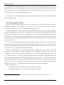
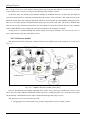
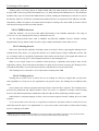
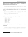
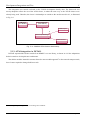
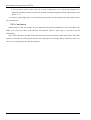
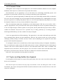
ATM is not a mere physical layer standard, at least not as the physical layer is placed in the OSI (Open
System Interconnection) stack.
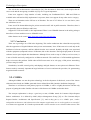
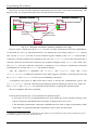
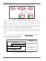
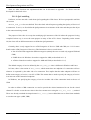
The ATM protocol reference model is shown in Fig. 3-2.
ATM Adaptation Layer
ATM Layer
T.C.
Physical
P.M.D.
Fig. 3-2 – ATM layers
The layer we are more interested in is AAL. We will briefly explain the usage of the others (as can be seen
in [26] and [27]):
· Physical Layer – it is divided in two sub-layers (as represented in Fig. 3-2):
Ø Transmission Convergence (TC) – maintains cell boundaries; checks and generates error control
code in the cell header (HEC (Header Error Control Code)); adapts the rate of valid ATM cells
to the payload capacity of the transmission media, by inserting or suppressing idle cells; packs
ATM cells into transmission frames for the physical layer; regenerates and recovers these
frames’ structure.
Ø Physical Medium Dependent (PMD) – this is the layer that really interacts with the underlying
physical medium. It therefore depends on which medium is used. Its job is to send and receive a
continuous flow of bits with timing information, and hence synchronize sender and receiver.
· ATM Layer – is responsible for establishing and maintaining the virtual connections. Using the
ATM cell header it multiplex/de-multiplexes the virtual connections, translates VPI/VCI
information on switches and cross-connects, adds/removes the header when receiving/passing the
cells from/to the AAL and implements traffic management functions.
The AAL is responsible for the adaptations of the SDUs (Service Data Units) from the layers above it to
the 48 bytes of ATM cells payload. It is its duty to translate the higher-level data units to and from an ATM
cell size and format. For this purpose, it is organized in two sub-layers:
· Convergence Sub-layer (CS) – the primary issues are: timing/clock recovery (when applicable),
message identification and error correction (when required).
· Segmentation And Reassembly (SAR) – the basic function of this layer is to receive the data units
from the CS and segment them (with possible some additional header/trailer) to fit into 48 bytes
ATM cells. The inverse operation (reassembly) is also the responsibility of this layer, on the receiver
side.
Communications Arch. for Distributed Multimedia Systems
18
Technologies Description
3
ITU-T [30] defined four traffic service classes (A, B, C, D) based on time relation between source and
destination, bit rate pattern and connection mode. The intention was to map them to ATM Adaptation Layers
protocol types. Initially four AAL types were defined AAL1, AAL2, AAL3 and AAL4. Later AAL3 and
AAL4 were merged (AAL3/4). As an alternative to AAL3/4 a simpler AAL was defined AAL5, which in fact
gained wider application than initially expected. This led to the following assignment (that is nonetheless
contested by some ITU-T members):
· AAL1 is intended for class A (in fact, the better known application is circuit emulation).
· AAL2 is intended for class B.
· AAL3/4 is used for classes C and D.
· AAL5 was initially sought for classes C and D, but it may be used for real-time services either with
constant or variable bit rate (classes A and B).
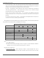
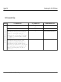
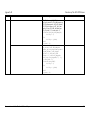
The characteristics of the classes are portrayed in the next table:
Parameters
A
B
C
D
Time relation
Yes
Yes
No
No
Bit Rate
Constant
Variable
Variable
Variable
Connection
Mode1
ConnectionOriented
ConnectionOriented
ConnectionOriented
Connectionless
Table 3-1: AAL Parameters
However, the Service Categories defined by the ATM Forum became more commonly used than the ITUT service classes (we will discuss these Categories next), because they had to do with the behaviour of the
ATM network as the provision of different QoS guarantees.
ALL5 is the most commonly used, because it uses lesser overhead and has better error protection. Not
most cards have support for other AAL; therefore, in our thesis we use AAL5 that is supported in both Linux
and Windows.
3.1.2. Service Categories and QoS
ATM is primarily used due to its QoS enforcement. To ensure the compliance with traffic contracts
established, ATM uses several functionalities, which are addressed in Traffic Management Specification by
the ATM Forum [29]. Some of the most important are:
1
This refers to the more suited connection that is on top of the AAL, for example, AAL3/4 is better suited for
connectionless connections.
19
3.1 ATM and QoS
3
Technologies Description
· Connection Admission Control (CAC) – during set-up or connection re-negotiation, determines if a
connection can be accepted; that is, if the network has resources to provide the requested QoS to the
new connection while not affecting the contracts already established.
· Usage Parameter Control (UPC) – monitors and controls the connections, ensuring that contracts
are satisfied. This feature implies shaping and policing traffic.
· Cell Loss Priority Control and Selective Cell Discard – the CLP (Cell Loss Priority ) field in the
ATM cell allows (when necessary) to discard cells that are less significant.
· Explicit Forward Congestion Indication (EFCI) – allows information about congestion to be
propagated, signalling a sender to lower the bit rate if network congestion occurs.
· Feedback Control – allows the network to regulate the traffic in the network by getting updates on
the state of the connections.
To do all these jobs, there are some parameters (related to traffic and to QoS) to evaluate if a connection
can be established (according to a specific contract) and if the contract is being honoured. Again, they are
defined in Traffic Management Specification by the ATM Forum [28] and we will describe the more
common ones.
Service Categories relate traffic and QoS parameters with network behaviour.
Traffic parameters:
· Peak Cell Rate (PCR) – is the maximum instantaneous nominal cell rate that a source can produce,
that is, the inverse of the minimum interval between cells. This definition applies to the ATM layer;
the cell pattern observed at the physical layer is affected by jitter and cell clumping may occur.
Therefore the interval between cells must be associated with a CDVT (see below) for policing
purposes.
· Sustainable Cell Rate (SCR) – this is an upper limit on the average rate of an ATM connection. It is
equal or less than PCR. It is evaluated using a larger time scale than for PCR.
· Minimum Cell Rate (MCR) – this is the minimum guaranteed bit rate for a connection.
· Maximum Burst Size (MBS) –It represents the maximum number of cells that can be sent at the
PCR.
· Burst Tolerance (BT) – it applies only to VBR connections (discussed later) and is used to shape
and policy traffic in place of MBS.
QoS Parameters:
· Cell Loss Ratio (CLR) – is the ratio between lost cells and transmitted cells. In some service
categories, the network guarantees this value during the existence of the connection.
Communications Arch. for Distributed Multimedia Systems
20
Technologies Description
3
· Cell Transfer Delay (CTD) – this value expresses the time between inserting a cell on the network
and its arrival at the other end. It includes transmission, queuing and processing time in every node in
the path, as well as packetization and depacketization on the end-systems.
· maxCTD – this parameter is used to characterize CTD. maxCTD is defined as the a percentile of
CTD, that is p(CTD>maxCTD) < a. This assumes that for real time services, cells that are delayed
beyond maxCTD are of no use and are therefore dropped.
· Peak to Peak Cell Delay Variation (CDV) – it is an estimate of the difference between the
maximum and minimum value of CTD (maxCTD as defined above and minCTD is the fixed part of
the CTD).
· Cell Delay Variation Tolerance (CDVT) – it is the tolerance (in anticipation) that a cell may have to
its theoretical arrival time (considering the nominal PCR).
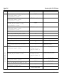
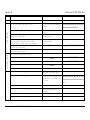
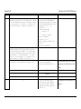
These parameters were used to define the service categories provided by ATM. The following table (from
[29]) summarizes the parameters that are meaningful in each category:
ATM Layer Service Category
Attributes
CBR
rt-VBR
nrt-VBR
UBR
ABR
Specified a
Specified
Traffic Parameters
Specified
PCR and CDVT
SCR, MBS and CDVT
n/a
Specified
n/a
n/a
MCR
Specified
QoS Parameters
Peak-to-peak CDV
Specified
Unspecified
MaxCTD
Specified
Unspecified
Specified
CLR
Unspecified
Unspecified
Feedback
b
Specified
Table 3-2: ATM Service Category attributes (from [29])
Notes:
a) See UBR explanation.
b) “CLR is low for sources that adjust cell flow in response to control information. Whether a
quantitative value for CLR is specified is network specific.” from [29].
Hence the service categories are:
· Constant Bit Rate (CBR) – makes continuously available a constant bandwidth. This value is
characterized by the PCR. The bit rate cannot exceed this value, but a lower bit rate can be used.
21
3.1 ATM and QoS
3
Technologies Description
This category is well suited for real time applications that require tightly constrained delay variation
and few data losses (voice, video, circuit emulation). Unused bandwidth cannot be used by other
services.
· Real Time Variable Bit Rate (rt-VBR) – this category is designed for real time applications that can
endure some data losses1 (which may depend on the particular application, which must negotiate an
adequate value). As can be seen, PCR, SCR, MBS and CDVT are specified. Therefore, the source is
to be considered “bursty”, not having a regular production of data. It needs however, very tight
bounds on delay. This service is intended for applications like compressed video or compressed
audio. As in CBR, cells that are delayed more than maxCTD are considered of little value to the
application. Statistical multiplexing is possible, but it has to be traded off with QoS guarantees.
· Non Real Time Variable Bit Rate (nrt-VBR) – this category is similar to the previous one. The only
difference is that there are no delay guarantees. Applications that use this service expect however a
small loss ratio. Examples are non-interactive audio or video, LAN interconnection, interworking
with frame relay. Average throughput is guaranteed. Statistical multiplexing can be exploited.
· Unspecified Bit Rate (UBR) – there are no guarantees in this category. It is a sort of best effort
service. PCR may not be enforced by CAC and UPC procedures, being only informational.
Nevertheless, PCR can be indicated and the network may optionally use this information. This
service is useful for applications able to cope with delays and/or losses, such as file transfer
program and mail programs. They can rely on error control mechanisms (such as TCP) when
needed.
· Available Bit Rate (ABR) – this category lets applications deal with bandwidth availability
variations. At connection establishment, a MCR (that can be 0) and a PCR are negotiated. The
application has the guarantee that it will have at least MCR of bandwidth, but it can have more. The
network will send feedback information to the end systems. This will lead to a small CLR. This
service is appropriate for TCP/IP traffic providing higher throughput than UBR, since it is expected
that by adapting the source rate, discarding of packets will be highly reduced and therefore the TCP
retransmission mechanism (slow-start, etc) will not be triggered.
It can be easily seen that there is a rich set of functionalities in ATM categories.
3.1.3. ATM addressing
At the beginning of this chapter, we mentioned addresses, when talking about SVC establishment. In fact,
there are three standard address structures proposed: E.164 from ITU-T, the DCC (Data Country Code) using
ISO (International Standard Organization) 3166 and the ICD (International Code Designator) using British
1
For the application a cell loss is either due to cell dropping by the network or the late arrival of cells (those exceeding
maxCTD).
Communications Arch. for Distributed Multimedia Systems
22
Technologies Description
3
Standards Institute as a registration authority. All this addresses have a size of 20 bytes. The ATM Forum
recommends using ICD or DCC in private networks.
The most important concept of a NSAP (Network Service Access Point) address is the following structure:
Prefix of 13 bytes
ESI of 6 bytes
SEL 1 byte
Fig. 3-3 – NSAP structure
The Prefix identifies a switch in the network (the end-user card inherits this value to is own address). The
ESI (End Station Identifier) identifies uniquely a device attached to a switch 1. The final element, the SEL
(Selector) is for identifying the process at the end station; it has no network significance, but it is of great
importance for the programmer.
The selector works like a port in TCP/UDP. We can choose to which service to connect to, as long as the
service is listening in the selector. An important difference from ports in TCP/UDP sockets is that when we
use the selector to connect to a service and a new connection is established (the server side accepted it), the
selector does not change. We end up with a new connection, but with an undefined selector (usually 0). This
is different from TCP/UDP ports where socket identifiers are well defined and unique for a given service. The
VPI and VCI are the only parameters that uniquely identify the connection in a machine; however, they have
nothing to do with addressing.
One byte in the selector gives a maximum of 255 services to make available in a station (with only one
ATM card).
3.1.4. CLIP and LANE
We have seen the layers in ATM and now know that applications can go on top of an AAL. Interesting is
to consider putting protocols on top of AAL. ATM can cope with IP, a layer 3 protocol, due to the AALs.
The “Multi-Protocol Over ATM Version 1.1” from ATM Forum defines the IP encapsulation over AAL5
frames. The overlay of IP on ATM is called Classical IP over ATM (CLIP). The RFC (Request For
Comments) 2225– “Classical IP and ARP over ATM” defines this ensemble. The RFC defines a one to one
mapping, in a LIS (Logical IP Subnetwork), of IP addresses to ATM addresses. Address resolution is solved
using ATMARP (ATM Address Resolution Protocol) servers that resolve IP to ATM address. It is like ARP
(in the Ethernet world) and hence its name. This approach usually means that ATM is a simple sub-network
(overlay model) and therefore offers the equivalent to a link layer connection. There are only point-to-point
connections, so there is no native broadcast or multicast available in CLIP. Every end system must know
about an ATMARP server or it will not get anywhere, so we need to define this in every node of the LIS. This
leads to the necessity of having an ATMARP server in each LIS.
1
This is similar to the MAC address of LANs.
23
3.1 ATM and QoS
3
Technologies Description
CLIP is probably the most used adaptation of ATM in private networks, because it is of easy
implementation in spite of its many limitations.
From this point forward when we refer to IP we mean IP over Ethernet. If CLIP is to be mentioned it will
be so directly.
Trying to provide an easier integration in the LAN, ATM Forum defined LANE (LAN Emulation) (“LAN
Emulation Over ATM Version 2 - LUNI Specification"). Its purpose was to hide ATM behind a MAC (Media
Access Control) interface, giving layer 3 protocols an interface that they already knew. LLC/SNAP (Logical
Link Control/ Standard Network Access Protocol) plus MAC encapsulation supports the largest number of
existing OSI Layer 3 protocols. The result is that all devices attached to an emulated LAN appear to be on
one bridged segment. Therefore, IP, IPX, Appletalk, etc. can “ride” on it. Hence, there is the possibility of
broadcast using classical applications. The reader is mentioned to “LAN Emulation Over ATM Version 2 LUNI Specification" from ATM Forum for further details.
3.1.5. Windows API
Microsoft and Intel developed Windows Socket 2.0 API (Application Program Interface) [39] to enhance
the former Windows socket API. In this new version support for multi-protocols was added, including ATM.
Windows sockets already had QoS, which in this version took advantage of ATM features. The ATM
Specific extensions document in [40] describe the added functionality in the API.
However, there must be support from the drivers of the card for some of the features of ATM, and the card
has to support the features as well. We used the ForeRunnerLE155 from former Fore Systems (now Marconi
Corporation [36]). We will nonetheless refer to the card as Fore’s, because it is the way it is better known.
The card only supported UBR and CBR1, but that was all that we were looking for anyhow. The driver SDK
(Software Development Kit) allowed us to access all the required Windows socket functions [31]2. The only
down size was that it only supported accessing VPI=0, but that was not a limitation since we were not using
more than 65535 connections.
VCIs below 32 were restricted (as the standard refers) and an error was generated if we tried to use them.
The Fore driver implements the ICD ATM address. CLIP and LANE are also available through the Fore
drivers. All and all, the API was fairly good for our needs.
3.1.6. ATM on Linux
Linux has started development of support for ATM in 1995 [35]. As in most software for Linux, the
development reached a vast community3. In the beginning, it was a patch for the kernel. Nowadays it reached
the state of development that allows it to be dispatched in the kernel source.
1
With a limit of 1000 rate shaped connections and a total of 16 different rates.
It even supports VBR, which the card we used does not.
3
Including INESC Porto, where the author of [41] developed the driver for the card we used.
2
Communications Arch. for Distributed Multimedia Systems
24
Technologies Description
3
The API for the socket interface is described in [32]. This document is from 1996, which implies that the
source code and the newsgroup (reachable in [35]) are of a great importance.
Linux now supports a large number of cards, including our ForeRunnerLE155. CBR and UBR are
available in the API and are fully implemented. At present, there is no support for any other service category.
There are no limitations on the VPI use as in Windows. The use of VCI below 32 is a user choice, since
the API allows its use.
Linux uses ICD format addressing for private networks and E.164 in public networks. Therefore, there is
interoperability between Windows and Linux.
Support for CLIP and LANE is also implemented. There is an ATMARP daemon in the utility packages
that allows a Linux machine to act as ATMARP server.
Other features can be seen in http://linux-atm.sourceforge.net/info.php.
3.1.7. Conclusion
There was a great hype on ATM in the beginning. This earlier enthusiasm has calmed down (especially
after the appearance of Gigabit Ethernet in the private environment). Now ATM seems to be used only in the
backbone of telecom operators, and has drifted from the user network. Probably the high costs associated
with the equipment (compared to those of Ethernet) led to this desertion. The huge deployment of IP based
software in user space helped this abandonment. Although IP can work on top of ATM (as we have seen), it
is not as flexible and easily configured as an Ethernet network. The small base of ATM enabled applications
helps to increase this problem. Unlike what ATM Forum states in its web page, ATM private networking
(end user usage) is small.
Nonetheless, its traffic control (policy and shaping) and QoS features are not quite met in Ethernet. These
features make it extremely important in huge backbones of service and network providers, for guaranteeing
negotiated traffic contracts.
3.2. CORBA
Although CORBA was not the prime technology in the development of this thesis, some of the classes
elaborated were based on CORBA generated classes defined from IDL (Interface Definition Language).
Therefore we will discuss some primary aspects of CORBA; it will be a lightly discussion with the only
purpose of getting the reader familiar with some of the features of CORBA used in this thesis.
The acronym explanation is always a good way to start; CORBA stands for Common Object Request
Broker Architecture. It is defined by OMG (Object Management Group) [19] on “The Common Object
Request Broker: Architecture and Specification” [3]. And as they put it, it is “OMG's open, vendorindependent architecture and infrastructure that computer applications use to work together over networks”
in a client-server approach. It is worth to point out that a server can also act as a client of other servers. This
25
3.2 CORBA
3
Technologies Description
is not portrayed during this discussion but should be present as we talk about servers and clients. Servers are
objects where methods are invoked and return (or not) some answer. Clients are the objects that do the
invocation.
CORBA is therefore related to distributed computing on multi-platform and multi-language systems. This
is its primary advantage: it is widely available on many platforms and OSes (Operating Systems) and it can
be developed in many languages (C++, C, Java, COBOL, Smalltalk, Ada, Lisp, Python and IDLscript 1). In
the same framework, we can have different programs written in different languages communicating with one
another using an interface defined previously.
This is where IDL comes in.
3.2.1. Brief comments on IDL
Interface Definition Language (or IDL for short) allows us to write interfaces in a language similar to C++
that can be mapped to any of the mentioned languages where CORBA is supported. This is a job for the “IDL
COMPILER”. It translates the defined IDL into proper code that is then integrated in the development
environment. Basically, it generates language specific stubs that enable the communication between clients
and servers. The defined IDL is the contract that the server agrees to abide, and clients must use to invoke
methods on the server. The IDL compiled code is responsible for marshalling the arguments sent. On the
server side, it un-marshals those arguments and gives them to the server. The server response (if there is one)
“suffers” the inverse path, to get to the client.
The IDL standard defines the types that can be used, when defining the interfaces. There is no possibility
of creating new types. The programmer can only define new classes (that is, new interfaces, using the
IDL keyword). These classes can have any attributes of the defined types and methods with arguments (input,
output or in-output) and return values (all also from the official list). There is a special variable type (any)
that can be assigned any type at runtime.
IDL also supports exception handling, so that errors can be reported to clients or servers in a flexible way.
The IDL mapping to a specific language has to define which native type in the destination language will
be used for the IDL types. This mapping is defined by OMG in a precise manner. Even for languages that do
not support exception handling, OMG defined a way to map the exceptions to a proper structure in the
language.
The IDL compiler will take as input the IDL file and generate code in the development language required.
Different compilers can be used to get mappings for different languages and platforms based on the same
IDL. This will not affect the desired behaviour of the client or the server.
1
There are also implementations mapping to other languages (although not standardised by OMG).
Communications Arch. for Distributed Multimedia Systems
26
Technologies Description
3
3.2.2. The ORB
“So where’s the broker? What’s its role in all this?”
The ORB (Object Request Broker) handles all the connections between clients and servers. It even
connects to other ORBs in order to deliver requests out of its objects pool. To do this, it has to know all
objects that export methods. Therefore, it handles an IR (Interface Repository), a database that stores
information about all the interfaces (and the signatures of its methods) that the ORB knows about.
The ORB is also responsible for de-activating inactive server objects and re-activating them when a
request for them arrives.
The ORB also has an IDL interface that allows access to its information. This can be an access to the IR or
to transform references of objects to string or vice-versa 1 (object references will be discussed later on).
Fig. 3-4 (taken from [3]) shows the primary components of the ORB and their relation to clients and
servers (with object implementation).
Fig. 3-4 –The structure of the ORB Interface (from [3])
The stubs we have mentioned previously provide the connection from the client to the ORB. The static
IDL skeleton is the stub on the side of the server object.
The ORB interface is the IDL that was mentioned earlier to access the functionality of the ORB.
The DII (Dynamic Invocation Interface) and the DSI (Dynamic Skeleton Interface) are used to discover
and access at runtime objects that are not known at compile time. It supplies a mean to query the ORB about
objects whose existence was not known and to call methods on them. For this purpose, it is also necessary to
use the CORBA services (described further down).
1
In versions above 2.4, it can also transform URL-format corbaloc and corbaname object references to session
references (see 13.6.10 of [3]).
27
3.2 CORBA
3
Technologies Description
This only leaves out the object adapter or, as it is usually known, the POA (Portable Object Adapter). This
is the successor of the Basic Object Adapter (BOA) that was deemed much too primitive to meet enterprise
and Internet requirements. As can be seen from the diagram, POA only exists in the server side, that is, the
client is not aware of any of its functionalities. POA is not known from the client’s point of view.
The primary POA duty is to manage server side resources for scalability. POA is responsible for activating
and de-activating objects’ servants. From the standard, we have: “A servant is a programming language
object or entity that implements requests on one or more objects”. This means that in fact the servant is the
one who executes the job requested by the client. The flexibility of this is that the servant can implement the
jobs of more than one object, or even there can be many servants (in the course of time) to implement the jobs
of a single object. For the client, as has been said, there “is not such thing as” a servant. Clients only
“believe” in objects.
The application can control many aspects of the POA, including the strategies for activation/de-activation
of servants.
A final note to Fig. 3-4 is the proprietary interfaces described. The ORB implementers define these ORBdependent interfaces. This makes the POA hardly coupled with the ORB core.
3.2.3. Method invocation
Now it is the time for a picture regarding the real object calling.
Fig. 3-5 – Method Invocation in same ORB and crossing ORBs (from [19])
In Fig. 3-5 we can see the client using the server object and the request passing the ORB. The first
example is of a client using a server object in the same ORB. The first interesting point, that we have not
focused yet, is addressing. CORBA uses IOR (Interoperable Object References) to reference objects. These
IORs can contain information about the ORB network address where the object resides, the protocols that can
be used to reach that ORB and the key that identifies the server object uniquely within the ORB’s space.
OMG states, “…this data structure need not be used internally to any given ORB, and is not intended to be
visible to application-level ORB programmers”. Clients are therefore completely unaware of this information,
which should only be used when crossing object reference domain boundaries.
Communications Arch. for Distributed Multimedia Systems
28
Technologies Description
3
Another point is accessing objects in another ORB. IORs tell what protocols can be used to reach the
foreign ORB. In the most general and standard way, it is IIOP (Internet Inter-ORB Protocol) 1. This definition
broadened the scope of General Inter-ORB Protocol (GIOP), making the standard more suited to be used in
the Internet. IIOP uses TCP/IP for communication and describes how to represent TCP/IP addresses on IORs.
Nonetheless, ORBs can optimise invocations between objects residing in the same ORB, by means of direct
calls instead of using network loop-back interface.
3.2.4. CORBA Services
OMG has defined a set of services that added functionality to the CORBA architecture. The range of
services is very vast, ranging from security to transaction services.
We will briefly describe those used in DIMICC and DETAIL (DIMICC Essence Transfer Already
Implemented Library) and the reader can refer to [4] for further information on the other services.
3.2.4.1. Naming Service
This service provides the capability of binding a name to an object. Then, by querying the Naming Service
with the name of the object, we can get the reference to it. Names must be unique within their context. The
use of contexts leads to a graph like organization, where names are the leaves of the graph and contexts are
the nodes. This obviously gives a better organized structure to the Naming Service.
When a server object wants to be available in this repository, it publishes itself using a name (in the
appropriate context). Then client objects that know its name (and its context) can query the Naming Service
(using the defined IDL) to access the object reference, and therefore access the object itself.
The Naming Service is therefore a server object that is running in the ORB.
3.2.4.2. Trading service
Naming Service works well if we know who we are looking for. However, imagine that we only know
what capabilities we need, but are not acquainted to any specific object. The Trading Service addresses this
issue.
Server objects now advertise properties and client objects search for these capacities. The Trading Service
provides the publication and inquiry facilities. There can even be a federation of traders where Trading
Services from different partitions communicate with each other to allow publicizing in farther regions.
OMG defines a constraint language to allow a more accurate response from the Trading Service to client
requests2.
As we can see this service also acts as a repository of references, but allows clients to search for services
rather then specific objects. It is implemented as a server object (and a client when it contacts other Trading
Services) running on the ORB.
1
2
ORBs may use other protocols besides IIOP, but for interoperability and CORBA compliance, they should use IIOP.
The Trading Service returns to the client object all references that match the specified query.
29
3.2 CORBA
3
Technologies Description
3.2.4.3. Event and Notification Service
These services decouple producers of events from their consumers. In practice, they allow an object that
generates events (e.g., a stock action object), to be unaware of other objects (stockbrokers) that are interested
in its events. Therefore, if a condition happens that triggers an event (the value of the action drops), the object
only sends this information to an event channel. The consumers have registered themselves in the event
channel to listen to it, so they are informed of this event. We can also add more object suppliers (more stock
actions) to the same channel. Every time that any of them sends an event, the consumers will receive it.
The Event Service defined this asynchronous and decoupled way of passing messages between objects. It
defined two models: the push and the pull models.
In the push model, the suppliers take the initiative of sending the event to the channel. Then the event
channel notifies consumers of this event.
In the pull model, consumers ask the channel if an event is present. The channel then reports any event
that it has. If there is not an event in the channel, the client can wait for it to happen, or return immediately. In
this model, clients poll the channel.
The Notification Service is a superset of the Event Service. It added an important filter capability.
Consumers can specify what type of events they want to receive (“I only want to know about Cisco,
Microsoft and Oracle stocks”). Producers can also know what type of events the channel (representing all the
consumers) is interested in, in order not to send events that nobody is listening to (“Compaq dropped its
value, anyone interested? No…OK then”). The ability to query the channel for the events that it offers was
also included in the Notification Service.
These two services exist as separated standards, as can be seen in [4]. The channels are objects that reside
in the ORB and act as servers and clients in the architecture.
3.2.4.4. Property Service
Properties of objects can be different from their attributes. A client should (would like to) be able to add a
special property to an object that is already running. It should also be able to query objects about their
properties. The Property Service intends so solve this. Objects that want to expose properties to client objects
implement a defined IDL (PropertySet, see [4]) that allows other objects to browse the properties and
even add some new ones.
As can be seen, each server object implements the interface and there is no central service to be accessed.
3.2.5. Final Notes
To end the CORBA discussion we should mention the existence of other important standards by OMG
related to CORBA.
Communications Arch. for Distributed Multimedia Systems
30
Technologies Description
3
Real-Time CORBA [6] is a standard to allow the use of ORBs in real time systems. It sacrifices in some
way the general nature of CORBA to provide predictability and resource management, enabling support in
time-critical systems. Real Time CORBA uses fixed priority and states that is general enough to cope with
hard and soft real-time systems.
Minimum CORBA is another important definition [3]. It declares a subset of CORBA features allowing
resource-limited systems to have an ORB definition. This minimum CORBA interoperates with the full
standard.
This concludes our “walk” through CORBA and some of its features. There are other distributed systems
that have better attributes than CORBA, but also lack some of its features. New models are now emerging
that, although criticized by CORBA fans, may deserve a look into.
31
3.2 CORBA
4
Programming Environment
4.
Programming Environment
“Computers are useless,
They can only give us answers”
-- Pablo Picasso
This chapter will describe the programming infrastructure used. All tools
used for development will be described here. We will first approach the
ACE framework and its patterns (at least the ones concerning the work at
hand). Next TAO, the ACE’s ORB, will be portrayed. A discussion of the
frameworks DIMICC and DETAIL for which the components were
developed will follow. At the end of the chapter we will briefly describe
other valuable tools used in the project.
4.1. ACE
All the development made during this thesis was based, or laid upon, the ACETM (Adaptive
Communication Environment) framework. That seems a strong enough reason to “stray” a little through the
concepts that make it one of the most used open-source object-oriented infrastructures for software
development.
As its acronym suggests ACE is aimed at communication, be it in the same machine (inter-process or
inter-thread) or between machines (using different kinds of underlying networks). The DOC (Distributed
Object Group) of the Washington University is developing this system. Since this is an open-source project,
Communications Arch. for Distributed Multimedia Systems
32
Programming Environment
4
user input and contribution from outside the group has been essential to the correction and improvement of
the framework.
From [16] and [7], we can state the major benefits of using ACE:
· Increased Portability – this is one of the main advantages of ACE. The code was developed so that
it would compile in various OS (Windows, Macintosh OS X, Linux, Solaris, IRIX, VxWorks, MVS,
Open Edition, etc.). In addition, being open-source and having some good guidelines for porting the
code enables the extension to other platforms.
· C++ Wrapper facades for OS interfaces – these classes wrap the OS calls, making it possible to
hide from the user program the specific call to the underlying system. This architecture is based on
the Facade pattern [20]. This group of classes encompasses concurrency, synchronization, inter
process communication and memory management (as can be seen in Fig. 4-1).
· Wide usage of patterns – most of the implementation is based on known patterns [20][25], which
eases the learning curve of the system. ACE itself generated a large number of new patterns that
have become widely known.
· High level framework – built on top of the wrapper facades there is a framework that exercises the
patterns developed and provides an enhanced interface to end-users (we will be discussing some of
the components of the framework in this subchapter)
· Increased efficiency and predictability – ACE integrates support for QoS on communications and
real time operations on OSes that support it.
· ORB adapter components – these classes enable the usage of single or multithread ORBs with ACE
seamlessly.
33
4.1 ACE
4
Programming Environment
All these points can be seen in Fig. 4-1.
Fig. 4-1 – ACE key components (from [16])
Following a recent trend in the art of programming (eXtreme Programming [55][56])), the DOC group
also claims to follow some of its guidelines. They proclaim [47] that although they have three of the major
contraindications for doing XP (eXtreme Programming) (large project, open-source and being a development
framework), the usage of XP has been in the group all along and they have tried to overcome their
contraindications.
We will now detail the ACE components and patterns used in this thesis. Besides the papers describing the
following patterns (and referenced in each section), there is also a good (although a little outdated) tutorial [8]
that covers all the aspects that we will be discussing.
For a reference of specific patterns, there is a good site in [25].
4.1.1. Reactor
The Reactor pattern [23] is an event de-multiplexing framework. General speaking, it acts as a central
event service where we can register ourselves for a specific event (or set of events). The Reactor will call a
specific method when the event registered happens.
Communications Arch. for Distributed Multimedia Systems
34
Programming Environment
4
We can register for common I/O (Input/Output) handles (sockets (BSD (Berkeley Software Distribution))
or System V TLI (Transport Layer Interface)), timer events (e.g., call us every 5 minutes or call us in 5
minutes), signal handlers or synchronization events.
Fig. 4-2, taken from [23] better illustrates the events. The reader should disregard the mentions to the
Logging, because they relate to an example given in the mentioned document, to present a real life usage of
the Reactor in a Logging Server (in this case only I/O handles are being used). There is also the reference to
the Acceptor class that will be discussed in the next sub-section.
Fig. 4-2 – Reactor Components (from [23])
The more attentive reader could already have guessed from the figure, that the Event_Handler class
has the methods to be called when the event happens. The developer should inherit from this class and
implement the methods it needs, the ones related to the event being listened to. In the I/O case, it is the
handle_input method.
From [23] we can state the following advantages/features of the Reactor pattern:
· Uniform OO de-multiplexing and dispatching interface – as can be seen in Fig. 4-2 the OS calls are
abstracted by the reactor framework, giving a uniform interface in the different OS APIs.
· Improved portability – from the previous feature, we can also see that the portability to different OS
is eased with this high-level common interface (as are all patterns in ACE).
· High/Low calls are decoupled – there is a decoupling of the low calls to the system (select,
WaitForMultipleObjects, wait, etc.) from the higher calls that deal with connection
strategies, data encoding/decoding, etc. The Reactor handles the lower part. This approach gives
several advantages:
35
4.1 ACE
4
Programming Environment
Ø Increased reuse – the lower code is reused letting the developer only worry about higher call
decisions.
Ø Error prone code is shielded to the user – the OS lower calls are more error prone than the
higher ones. Letting the reactor handle this part eases the programmer’s job.
· Automate event handler dispatching with state information – the event handlers developed by the
programmers are objects rather than functions, enabling state information to be maintained across
multiple calls. The appropriate method of the object is called according to the event that has
occurred. The same object can even register itself for different events.
· Efficient de-multiplexing – the Reactor uses sophisticated algorithms to perform event demultiplexing and dispatching logic efficiently.
· Thread safety – the Reactor was coded with threads safety in mind. So the programmer can have
multiple threads using the same Reactor or run different reactors in different threads. From [23]:
“The Reactor framework provides the necessary synchronization mechanisms to prevent race
conditions and intra-class method deadlock”.
The Reactor was widely used in the DIMICC (see 4.3) and DETAIL (see 4.4) development, because
connection establishment is of high importance and the use of this pattern gives all the advantages mentioned
above.
4.1.2. Acceptor - Connector Pattern
The main purpose of this pattern is to separate roles in communications. It identifies three separate roles:
· Passive endpoint à Acceptor – it only waits for connections, and creates the handlers for those
connections.
· Active Endpoint à Connector – it initiates the communication by connecting to the passive
endpoint. It creates the handlers after connection establishment.
· Effective communication à Service_Handler – it handles the data transfer, the sending and
receiving of bytes.
Communications Arch. for Distributed Multimedia Systems
36
Programming Environment
4
The first two classes form the connection establishment part; the latter is the actual communication. The
diagram in Fig. 4-3 (adapted from [24]) shows the relations between the classes.
SERVICE_HANDLER
SERVICE_HANDLER
Connector
Acceptor
Activates
connect() 1
complete()
Service_Handler
n
open()
Notify when connection
completes
Activates
n
1
accept()
open()
Notify when new
connection arrives
Reactor
Fig. 4-3 – Acceptor-Connector relations (adapted from [24])
Here we can see a fourth class, the Reactor1. Its role is to allow asynchronous connection establishment.
As discussed (see 4.1.1), by using the Reactor we can delegate the event waiting to the Reactor’s thread.
This way the Acceptor can start its service and then register a handle on the Reactor and wait that a
connection is initiated without being stopped by that wait. The Connector can use the same approach: it
starts the connection, but instead of waiting for it to complete it delegates on the Reactor this “dead” time.
The Reactor will call it when the connection is completed. As it is obvious, if synchronous connection
establishment is to be used, the Reactor can/should be dropped.
After the connection is established, the Acceptor and Connector create each a new
Service_Handler to handle the connection (as the name suggests). The data is sent using this class and
the Acceptor and Connector are left to go on establishing connections.
A programmer only needs to inherit from these classes to develop the communication system. The
Service_Handler is directly connected to the underlying network technology (sockets, TLI, ATM, etc.).
The Acceptor and Connector are responsible for the strategies of getting the connection made.
The use of templates allows this separation.
From the discussion and [24], we can summarize the patterns features:
· New types of services (or implementations) are easily added, due to the separation strategy of the
pattern. Connection establishment does not need to be changed for a new service.
· The inherently asynchronous connection establishment can be used to improve performance (make
large number of connections through a high-latency WAN (Wide Area Network))
1
Although we used a Reactor class in the diagram, other patterns can be employed, as long as they implement an event
de-multiplexing pattern (for further details see [24]).
37
4.1 ACE
4
Programming Environment
· Portability is made easier, as only the Service_Handlers need the large adaptations.
· Programmers are protected against the incorrect use of handles that only accept connections (one
might by mistake write or read to it).
4.1.3. Stream Architecture
In a simplistic way, the Stream Architecture [11][12] is like a protocol stack, in which we can build our
own layers. In this analogy, the Stream class is the protocol stack and the Modules we put in the Stream are
the protocol layers.
Fig. 4-4 will help our discussion.
Application
Stream
Stream
Head
Legend
Reader Task Object
Message Object
Upstream
Writer Task Object
Downstream
Module Object
Other home made
Modules
Stream
Tail
Network Interface or
Pseudo Devices
Fig. 4-4 – Stream Components (adapted from [11])
As we can see, an application builds a Stream object and then uses it to send and receive data. What the
Stream does with this data depends on the Modules the application has put in it. In the diagram, we can
see that there is a Stream Head and a Stream Tail, these two Module objects exist in every stream and do not
need to be put in by the application. They can however be circumvented (as discussed later on).
Besides the two already built-in Modules, the programmer can develop its own Modules and insert them
in the Stream. To do this the developer has to write two classes that inherit from the Task class: a Writer
Task and a Reader Task. As the name suggests, these classes do the write and read job, respectively, in
the Module. In the figure, we can see these two Tasks in each Module. The programmer uses the
developed Task classes to create a Module object that uses these classes. It then inserts the newly created
Communications Arch. for Distributed Multimedia Systems
38
Programming Environment
4
Module in the Stream. There can bee as many modules between the head and the tail of the Stream as
the programmer wants/needs.
The head and tail modules only act as a default. In fact, the tail module discards messages in its write task
and does not have any way of getting messages in its read task. So the developer should develop a tail module
class (or better two tasks for the last module before the tail) that implement the desired behaviour (in the case
of this thesis, we developed two classes that write and read to an ATM network). This Module will then
circumvent the Stream Tail, by writing/reading directly from the target object (be it a network or other I/O
mechanism). The Stream Head cannot be easily circumvented since the application only has the Stream
API; this interface calls the Stream Head directly.
We have not mentioned another important class shown in Fig. 4-4, the Message class. Every Task has a
message queue that contains all the messages to be sent (they can be sent synchronously or asynchronously,
as will be discussed). A message can be a linked list of messages itself and that is why they were represented
connected in the diagram. The message passing in the Stream is only pointer passing, as only the reference
to the message object is passed, rather than a copy of the message. Obviously, this leads to a better
performance.
The message passing is done directly to the next Task, not to the module itself. A Task writes (passes
the messages reference) to the next Task in the stream (be it up or downstream) after having done its
“thing”. The Task’s next Task is defined when the Module is inserted in the Stream1.
Regarding the inserting of Modules in the stream, there is also the possibility of removing a Module
from the Stream. We can even insert a Module in a specific position. These two functionalities give a wide
range of reconfiguration possibilities for a Stream.
In [11] there is also a reference to a Multiplexor class. This class could handle the input of more than
one Stream and multiplex/de-multiplex messages for each associated Stream. We have not seen in ACE
any implementation of this, so we only refer it here and not in the previous figure.
As mentioned earlier, each Task can handle the messages synchronously or asynchronously:
· Synchronously - when the previous Task passes the message we treat the message as we were
programmed to and send it to its destination (next Task, network, device, stream head, etc.)
· Asynchronously – when the previous Task passes the message, we put it in the Message Queue
and process it in a separate thread. This thread gets the messages from the queue, treats them as
programmed and sends them to their destination.
1
This can be related to the Module insertion order, or using an API that enables the insertion of a Module in a specific
position of the Stream.
39
4.1 ACE
4
Programming Environment
Fig. 4-5 taken from [11] illustrates this.
Synchronous
Asynchronous
4: svc()
Legend
Module Object
1: put()
3: put()
2: svc()
Writer Task Object
Reader Task Object
2: put()
1: put()
Process or Thread
Fig. 4-5 – Synchronous and Asynchronous behaviour in Streams (from [11])
In the synchronous behaviour there can be as many process/threads as the applications has. Each time the
put() method is called the Task borrows the process/thread to treat the message and passes it to the next
block. The first call only returns when the message is passed to its final destination.
In the asynchronous behaviour, the message handling is not done in the put() method, but it is
postponed to the svc() method. When called, put() only queues the message in the Message Queue.
The svc() function then runs in its own thread (and not that of the caller of put()) and processes the
messages in the queue. This thread is continuously checking the queue to treat more messages that may
arrive.
As one can imagine, each Module in the Stream can have different behaviours. Module 1 can work
synchronously and Module 2 asynchronously. We can also have the writer and reader Tasks of the same
Module acting differently. This leads to a very flexible architecture for message processing.
The Stream architecture was used in DETAIL, as will be seen in 4.4 and 5.1.3.
4.1.4. Service Configurator
This pattern [9][10] is related to providing services in a machine, primarily network services. It is a superserver as inetd (or more recently xinetd)1 in UNIX systems, but with more “salt” into it.
The main intent of the Service Configurator is to “decouple the implementation of services from the time
at which the services are configured into an application or a system” (from [10]). It also adds a centralized
control of services provided by a system.
1
inetd and xinetd have no reference in the bibliography as they were not of particular relevance to this work. However,
the more interested reader can learn more about these services in “ UNIX Network Programming” by Richard Stevens and
http://www.synack.net/xinetd/, respectively.
Communications Arch. for Distributed Multimedia Systems
40
Programming Environment
4
With this pattern we can start, end, pause and resume services at run-time, i.e., dynamically. If a service
changes its implementation but not its relation with other services and/or system, it should be possible to
shutdown the service, replace the implementation and restart the service. This should be done without
stopping other services or the system. The Service Configurator allows this.
Fig. 4-6 shows the state diagram for a service with the Service Configurator.
Configure/
init()
IDLE
fini()
Running
Reconfigure/
init()
resume()
fini()
suspend()
Supended
Fig. 4-6 – State diagram of the service Life Cycle (from [10])
The idle state is when the service is shutdown.
The Service Configurator must therefore be a process or thread. It registers the service that it is asked to
load in a service repository. The repository also keeps information about the state of the service.
The Service Configurator daemon manages the service reconfiguration. The user calls its API, or uses a
file in the system that has the action(s) to be performed by this super-server. These orders will change the
state of a service(s), getting it (them) into one of the states in Fig. 4-6. The commands can include
concurrency strategies (that can be different for each service).
When a service is loaded it generally registers itself for events (I/O, network, etc.). Using the Reactor
pattern (see 4.1.1), we can then map handlers from the services and let the Reactor wait for the event in the
place of the service. This way we have a single process listening 1 to events that it dispatches to services that
can handle them.
The discussion so far may have implied that the Service Configurator is separated from the application,
running in its own space. This is not what happens. In general, the super-server is a separate thread from the
application that handles the loading/unloading of libraries for the application. This is the case for the tools
developed in ORBIT (see 2.4).
1
This also leads to a single point of failure, but the architecture of a super-server has this inherent problem.
41
4.1 ACE
4
Programming Environment
In summary, the benefits of the Service Configurator are (from [10]):
· Increased modularity and reuse – the ability to add/remove services without disturbing other
services and maintaining their relationships.
· Increased dynamism – re-making an implementation and being able to remove the old one and add
the new one gives this flexibility.
· Centralized administration – one process/thread handles the services (using the repository), and an
administrator can configure the services from this single point.
The drawbacks are (also from [10]):
· Lack of determinism – only when an application has all services running can we determine its runtime behaviour. Real time systems may suffer from this.
· Increased overhead –we could conclude, after this brief discussion, that overhead is clearly
introduced by the associated call indirection.
· Reduced reliability – the interaction between the services can mean that a faulty service could
undermine the availability of the other services (especially the ones running in the same process).
4.1.5. Existing ATM support
ACE already had ATM support, before we picked up this project. It was available in Windows and Solaris
systems, and directly connected to the FORE API.
The code was based on the socket classes (for Windows) and the Transport Layer Interface (TLI) classes
(for Solaris). The defined classes were aimed at giving an equal interface that the ACE connection classes
already provided (for other network technologies).
The ATM infrastructure in ACE lacked the following aspects (some essential to our project):
· Support for Linux.
· Functions that allowed the use of the classes with the Acceptor-Connector pattern.
· A complete interface coherence with the other connections classes.
Nonetheless, the required skeleton (the classes) was already defined. It only lacked some more flesh
(functions and Linux implementation).
4.2. The ACE ORB (TAOTM)
Although ACE allows the usage of other ORBs (with the ORB adapter classes), the DOC group developed
a real time CORBA ORB, called TAO (The ACE ORB) [17].
Communications Arch. for Distributed Multimedia Systems
42
Programming Environment
4
Built on top of the ACE components, this ORB dwelled with some major points:
· Open-source, freely available and CORBA compliant ORB.
· “Empirically determine the features necessary to allow the real-time CORBA ORBs support
mission-critical applications with deterministic and statistical QoS requirements” from [17].
· Use real time I/O subsystem architectures and optimisations with ORBs to provide predictability
and QoS parameters, on and end-to-end system.
This work led to a deep involvement with OMG to release the Real-Time CORBA standard [6].
The effort also gave birth to TAO based on ACE components. Further development is underway so as to
make TAO fully compliant with the Real-Time CORBA 1.0 Specification [6].
The following diagram block (Fig. 4-7) shows the architecture developed. It is worth to notice the real
time blocks and that the network can be ATM based (as mentioned in 4.1.5, ATM was already partially
supported by ACE).
Fig. 4-7 – TAO block diagram (from [17])
When the project where this thesis is embodied started, TAO was still too young to be adopted (as
portrayed in [51]). However, its growth and progress led to the project’s embracement with this ORB.
The advantages were obvious:
· Several CORBA Services were already provided: Naming Service, Trading Service, Event Service,
Notification Service, Property Service, Security Service and more.
43
4.2 The ACE ORB (TAOTM)
4
Programming Environment
· It is based on ACE, which was already used and agreed to be an excellent platform.
· Same advantages of ACE: open-source, freely available and supported in multi-platforms.
4.3. DIMICC version 1
As can be seen in the Acronyms Section, DIMICC stands for Distributed Middleware for Multimedia
Command and Control. This architecture was developed in the Atlantic project (described in 2.3) to provide
(as the name suggests) a distributed control of multimedia software, more precisely, targeted at a television
studio distributed service environment. The primary objective was to define a common API that allowed the
control of acquisition, transfer, composition and broadcasting equipment in a distributed way (being the
equipment purely software based or hardware controlled by software).
DIMICC’s architecture is divided into four planes [42][51]: the system plane, the metadata plane, the
control plane and the essence transfer plane. In each plane, CORBA is used to provide distribution in an
object-oriented way. The reasons for choosing CORBA were from [42] “… the open, vendor independent,
highly available technology…” and the need to build DIMICC on an “… existing de jure or industry
standard”. CORBA fully fitted these requirements.
The System Plane takes advantage of some CORBA services to give the user the possibility of
management. Therefore, Naming and Trading services (see 3.2.4.1 and 3.2.4.2 respectively) are used to allow
the client application to find the needed services from DIMICC (which are publicized by DIMICC in those
services). The CORBA Notification Channel (see 3.2.4.3) is also used to allow the monitoring of the
infrastructure in a more decoupled way (producers of events are unaware of the consumers).
The Metadata Plane served only to ensure minimal mechanisms for relating Metadata and Essence. The
core of the plane was its Essence Locator Service that mapped UMIDs (Universal Material Identifier) to
CORBA references, that is, made possible the connection of the Metadata essence identifiers to the CORBA
essence objects of DIMICC.
The two following planes are more related to the work described in this thesis, as they concern the
communication and its control.
The Control Plane ensures control of resources and mechanisms to report events. A general base class
derives from PropertySet from CORBA Property Service (see 3.2.4.4), which allows clients to enquire
objects about their properties, namely the notification channel associated with them.
Communications Arch. for Distributed Multimedia Systems
44
Programming Environment
4
The control of resources (more to our interest) is better described with the use of Fig. 4-8.
Component
1
n
VirtualComponent
Endpoint
1
1
n
1
n
Sink
disconnected()
connected()
n
Source
addSink()
removeSink()
Fig. 4-8 – Control Plane Simplified Architecture
The Component class maps the resources being accessed. As more than one user can control a
Component, the VirtualComponent was defined to address session management. This class is
responsible for giving the user access to its Components. This VirtualComponent owns the
communication points, and as the name suggests Sinks are used to receive essence and Sources are used to
produce it. These two classes are the abstraction to the client of the underlying network. They derive from a
more generic class, Endpoint that hides the technical aspects of the communication.
The control is extended to legacy devices using proprietary protocols. For this purpose, management
proxies were developed to export the DIMICC API to clients and map this interface to the specific protocol of
the device.
The ‘essence‘of our work was related to the forth plane: the Essence Transfer Plane. Not surprisingly, it is
related to the transport of essence through the network.
Fig. 4-9 taken from [42] shows the stack defined.
Client Applications
DIMICC
Essence Transfer API
DIMICC Essence Transfer Library
CORBA
Network-dependant
API
Networks
Fig. 4-9 – Essence Transfer Protocol Stack (from [42])
45
4.3 DIMICC version 1
4
Programming Environment
CORBA is not used to transfer data, but only to control the Sinks and Sources that interact with the
network.
The client program initiates the connection establishment by asking, via CORBA, the Source to connect
to a Sink (addSink). Still in the CORBA world, the Source asks the Sink for its SAPs. After a polite
answer from the Sink, the Source chooses a SAP (Service Access Point) and a connection is set up now
via the network associated with the chosen SAP. At the end, the Source informs the Sink of the
connection descriptor that will be used between the two; this descriptor maps to the same network connection
on both sides. It is the identification of the connection.
The Acceptor-Connector pattern, discussed in 4.1.2, is used to establish the connection.
The client can request special attributes for the connection, which constrain the SAP selection by the
Source. A SAP that satisfies these needs must be chosen.
QoS parameters can be included in the requirements. For this to work both the Sink and Source have to
own SAPs associated with a protocol that supports QoS. This is where ATM comes to place.
This connection establishment is abstracted by the use of an UNManager. This class holds references to
classes that handle the specific connection, with the underlying network. This way the Sinks and Sources
resort to UNManager to set-up the connection between the two.
Fig. 4-10 describes the relationship between the classes.
Sink
disconnected()
c onnected()
UNManager
Source
TransportManager
1
addSink()
removeSink()
ConcreteTransportManager
Fig. 4-10 – Connection Managers in the Component
A Component has these classes to provide connections with other Components. The
ConcreteTransportManager classes that a Component has depend on the underlying network
technology supported by the Component.
There is a high-level multicast implementation, by making the same Source connect to more than one
Sink. The functions from the previous figure illustrate that (addSink and removeSink).
Communications Arch. for Distributed Multimedia Systems
46
Programming Environment
4
An important final note is that all the system was developed based on ACE (see 4.1) (as an example
ConcreteTransportManagers are loaded using the Service Configurator pattern (in 4.1.4)), which
allowed code portability across OS in an easier way. Since the target OS were Linux and Windows, this was
an essential point for better code development and a more reliable maintenance.
4.4. DETAIL and DIMICC-2
Even though it had strong points, the first version of DIMICC had some drawbacks:
· The connections were not sufficiently modular.
· The abstraction to the end user could be improved.
· It was somehow limited regarding network management.
The original group that developed DIMICC redesigned it (making the second version) and added DETAIL
(DIMICC Essence Transfer Already Implemented Library).
DIMICC maintained all the previous functionalities and a new modular infrastructure for the essence
transfer was added. The goal was to make the connections able to integrate functionalities as push modules,
i.e., we could insert functionalities by adding modules to the connection structure. This feature used the
Stream Architecture of ACE described in 4.1.3.
47
4.4 DETAIL and DIMICC-2
4
Programming Environment
The overall architecture was the same but the Stream Architecture was added. Fig. 4-11 better illustrates
this point.
ACE_SYNCH
ACE_Task
(from ACE)
writer
1
ACE_Stream
(from ACE)
ACE_Module
(from ACE)
In fact these relationships
are done by using a vector
of size 2
1
n
reader
1
ACE_SYNCH
1
ConnectionStream
1
ConnectionModule
ACE_Task
(from ACE)
n
ConnectionTask
Sink
Source
Fig. 4-11 – DIMICC-2/DETAIL transport architecture
Here we can see the ACE classes and the DETAIL defined ones implementing the Stream architecture.
Now Sinks and Sources have ConnectionStreams for the connection establishment.
We should note that a Sink only handles one ConnectionStream, since it is the endpoint of the
connection. The Source, on the other hand, can have more than one ConnectionStream, enabling
multicast at a higher level (as for the first DIMICC version).
When the client requests the connection between a Source and a Sink it may ask for special
connection attributes (reliability, frame formatting, QoS, etc.) and the ConnectionModules needed for
these functionalities are inserted in the ConnectionStream so that the stream has what it was asked for
(as long as it is available at either end, as in DIMICC-1). For example, if the client requested reliability and
frame format1, a TCPModule and a FramingModule should be inserted in the stream to be created at both
ends.
To be more precise, what is defined are the TCPConnectionTasks and the FramingConnectionTasks.
These are then used to build the two generic ConnectinModules that are inserted in the
ConnectionStreams at each side.
What the client is really defining, when he requests a connection, is a protocol stack, although this is done
implicitly, since the client only knows about informal requirements.
1
By frame format, it is understood a mechanism to format the output in fixed size frames. There is a check to see if
frames are received completely and correctly (this module was created as a part of the DETAIL development).
Communications Arch. for Distributed Multimedia Systems
48
Programming Environment
4
The sequence diagram in Fig. 4-12 will help to better understand the steps in the creation of a connection.
Here the User Program explicitly tells the Protocol Stack what he wants (this contradicts what was
previously said; there are two reasons for this: first, the development of the abstraction layer has not been
done and second the diagram is simplified by this removal).
Fig. 4-12 – Sequence Diagram for SourceóSink Creation and Connection
Here we can see that there is a ConnectionManager associated with the Sink and the Source. This
ConnectionManager is the “side” of the Endpoints that is seen by the clients. These classes have the
methods to interact with the Sink and Source. This way the Sink and Source are to the UserProgram
only part of the VirtualComponent (maintained from version 1) and the managers are the correct way to
control them.
As has been said, the UserProgram could be a DETAIL inner class that maps the client options to a
protocol stack. This class should check both Sink and Source for the requested protocols.
Two new classes are introduced: Manager and NetManager. These classes provide an interface to the
component, regarding connections. Manager is a high-level class concerned with Sink and Sources.
NetManager deals with the specific connections and the other Protocol Managers.
49
4.4 DETAIL and DIMICC-2
4
Programming Environment
Let us analyse two other sequence diagrams to better understand the job of the NetManager: Fig. 4-13
and Fig. 4-14.
: InnerDetailClass
ConnectingSide :
Net Manager
ConnectingSide :
ProtocolManager
s etupSt ream (ProtocolSt ack&)
:
ConnectionM odule
ConnectingS ide :
ConnectionS tream
ConnectionStream( )
setupConnection( )
ConnectionModule( )
push(ConnectionModule)
For each Protocol mentioned in
setupStream, contact the appropriat e
ProtocolManager to setup the
connect ion and push the Module.
Fig. 4-13 – Creation of the Stream in the Source/Connecting Side
Now we named the class initiating the sequence an InnerDetail class, to illustrate what we have stated
previously. When asked to set-up a stream, the NetManager creates a new ConnectionStream. Then it
evaluates the protocol stack and asks the required ProtocolManagers to create a ConnectionModule.
Each ConnectionModule is then pushed into the stream.
One of these modules will have to construct the network access. We have not mentioned it yet, but it must
be clear that only one module will connect to the underlying network in each stream. There can be modules
that deal with the data being sent/received (as the Framing module described earlier), but only the bottom one
(see 4.1.3) will send whatever data it receives from the above modules to the physical network bellow it (be it
FastEthernet, ATM, or other).
Having said that, it must be stated that in the previous picture, this connection is missing. This means that
the ProtocolManager for the underlying network in addition to creating the module also makes the
network connection to the Sink, using the Acceptor-Connector pattern mentioned in 4.1.2.
Communications Arch. for Distributed Multimedia Systems
50
Programming Environment
4
With this in mind, we can now view the sequence diagram for the accepting side in Fig. 4-14.
: Acceptor
: InnerDetailClass
AcceptingSideNetwork :
ProtocolManager
AcceptingSide :
NetManager
AcceptingSide :
ProtocolManager
:
ConnectionModule
:
ConnectionStream
notifyNewConnectionAc cepted( )
ConnectionModule( )
findStream( )
ConnectionStream( )
findConnection( )
ConnectionModule( )
push(ConnectionModule)
For each Protocol mentioned in
findStream, contact the appropriate
ProtocolManager and push the
Module
Fig. 4-14 – Creation of the Stream in the Sink/Accepting Side
In this diagram we have included the Acceptor that accepts (as per its name) incoming connections. We
have therefore added the underlying network to our schematic. This Acceptor is especially crafted for the
protocol in question, that is, there is an Acceptor defined for each network protocol. The incoming
connection triggers the creation of a new module that handles it. The Acceptor(s) is (are) created when the
ProtocolManager initiates (we will see in a while the reason for the plural).
The rest of the diagram is similar to the one from the connecting side, except for the method names.
There is also another fact to note: when the NetManager calls findConnection() on the network
ProtocolManager, this one does not create a new module but returns the one previously created when it
was notified of new connections. There is an identifier that is passed by findConnection() that allows
the identification of the correct incoming connection.
Only one ProtocolManager object of each type is created in each process. This way a
ProtocolManager handles all VirtualComponents in the process. This is the reason for a network
ProtocolManager initiating more than one Acceptor, because it has to create Sinks for each
VirtualComponent that it owns. Each ProtocolManager is loaded as a separate library using the
Service Configurator pattern described in 4.1.4.
As final remarks, we should state some important aspects of DETAIL and DIMICC:
· Data passing between modules is optimised using Messages Blocks from ACE, which allows
passing pointers only, avoiding the cost of copying the data (as described in 4.1.3).
51
4.4 DETAIL and DIMICC-2
4
Programming Environment
· It uses the Reactor (see 4.1.1) to allow event decoupling.
· Code portability is ensured, because of the use of ACE classes.
In this sub-chapter, we have not stated clearly the separation between DIMICC and DETAIL. The reason
for this is the high coupling between the two. In rough, we can say that DIMICC defines the IDL interfaces
for accessing Components, Sinks, SourceConnectionManagers, etc. This allows a different
implementation of these classes as long as they comply with the interface. Programs that use this interface
will not be affected by that change.
DETAIL is the implementation of the interfaces, with all underlying aspects.
4.5. Other used tools
The project developed to a size where industry quality assurance was needed. This led to the use of a set
of tools that created a more reliable environment for the intended development.
4.5.1. Bugzilla
Bugzilla [59] was introduced to better catalogue and address ‘bugs’ in the system. This tool gives support
for error notification/resolution flow. It is a defect-tracking system, as their developers put it.
From [59] we can state the following strengths of Bugzilla:
· Web access to the defect-tracking system.
· Immediate notification of ‘bugs’ reported.
· Annotations to the ‘bug’ lifecycle.
· ‘Bug’ searching capabilities.
· Inter-’bug’ dependencies and dependency graphing.
· Advanced reporting capabilities.
· De-facto standard defect-tracking system.
Bugzilla provides a web interface that allows adding ‘bugs’ discovered and associate them with
components of the system. A programmer manages the components and is warned of each ‘bug’ reported.
There is also the possibility of assigning the ‘bug’ to a specific programmer besides the responsible of the
component. Severity, dependencies, ‘bug’ duplicates can be noted to help to categorize the errors. A search
engine is also available to search for ‘bugs’ reported.
Not only the reporting of ‘bugs’ is available, but also all the discussion related to the resolution of the
‘bug’ can be seen in the web interface.
Communications Arch. for Distributed Multimedia Systems
52
Programming Environment
4
It uses a database behind it to store all the information. As of the time of this writing, it only supports
MySQL (see http://www.mysql.com/) but the development team plans to add Database Modularity, so to
remove MySQL specifics and enable multi-vendor Database support.
As the mentioned site says, it has become a widely used defect tracking system.
4.5.2. CVS (Concurrent Versions System)
CVS was another needed tool. As one might expect, the number of components in the system was growing
quickly. The compatibility between different versions became hard to control, and the changes made to each
file difficult to track. The obvious solution was to adapt version control. CVS [60] was the natural solution.
Further, it is a free and widely used solution and it had support in both Linux and Windows, the systems
where development was been made. The web interface supplied by an additional add-on CVSWeb [61], made
it a very productive tool.
As the name suggests, this product allows the concurrent development of the same source code (or any
other document type) in each programmer’s space. This parallel work can be merged at any time when a user
checks in the changes he made. Note that we mentioned differences between the current version (in the
central repository) and the local copy of the programmer. Keeping track of changes rather than the whole new
file minimizes space needed and eases comparison of versions.
As mentioned, there is a central repository where all the versions reside. This depot stores all the directory
tree of a project (or projects), including files removed/added during the course of the project. There is even
the possibility of creating new branches (following different approaches or problems) in a development and
then merging them back when desired.
Although we have not pointed out, the development and central point can be in different locations in a
network, and this network can be the Internet.
Other major features are:
· Tagging the state of the development tree (e.g., version 0.0.3) and getting differences between
tagged versions.
· Changes are logged with developer comments.
· There is the possibility of interacting with external ‘bug’ systems (although this was not pursued in
the development).
The mentioned web interface (CVSWeb) adds an easier way to view committed changes and track those
changes. It allows us to see the evolution of a specific file and comparing any two versions, by just selecting
them in a web browser. This is all based in the CVS installed in the system where the web server runs
CVSWeb.
All and all, CVS proved to be the solution it claimed.
53
4.5 Other used tools
4
Programming Environment
4.5.3. Doxygen
Doxygen is a very helpful tool for documenting source code [62].
We needed to develop documentation for the code implementation in the easiest and quickest possible
way. Doxygen takes its input from the source code, or better, from the comments in the source code. It has a
set of rules for the comments that it can handle. Following these rules is straightforward and even improves
the comment layout of the source code. C, C++, IDL and Java are the languages that can be parsed. As the
development was in C++ this small limitation was not troublesome.
Commenting the code is not even needed to generate code structure, it is extracted from the code itself,
without user intervention. This is useful to get relationships in large code developments.
Doxygen can generate several formats for the output, HTML (Hyper Text Markup Language) being the
friendliest of all. Hyperlinked PDF (Portable Document Format), PS (PostScript), RTF (Rich Text Format),
compressed HTML for Windows help files and UNIX man pages are the other format options. The developer
can/should format the desired output in a file (similar to a makefile for a compiler) that Doxygen takes as the
configuration for the generation of the documentation.
Besides this, we can also list the following features:
· It is available in various OS (Linux, Win32, UNIXes).
· Automatic generation of references to documented classes, files, namespaces and members.
· Graphically generated structure/relationship of the code (for this it uses the dot tool [63]).
· Can use references generated for other projects.
· Source code fragments are highlighted.
· “Includes a fast, rank based search engine to search for strings or words in the class and member
documentation” from [62].
Summing up: Doxygen is a very powerful tool. The ATM documentation generated during the
development of this thesis can be seen in http://bluenose.inescn.pt/~pbrandao/develop/. Examples of the code
comments can be seen in Appendix C-2 in the IDL file.
Communications Arch. for Distributed Multimedia Systems
54
Programming Environment
55
4
4.5 Other used tools
5
Development/Integration and Test
5.
Development/Integration and Test
“I’d love to change the world…
But I can’t get the source code”
-- Unknown
This chapter is totally dedicated to describing the developments made
during the course of this dissertation. First, we shall look at the ATM
development and then discuss the ACE classes developed and some
details concerning them. QoS and OS specific versions will be described.
The integration of these classes in the DIMICC and DETAIL framework will
be the next point of discussion (regarding ATM development). Then the
chapter will end with some considerations concerning the test structure
used to improve quality in the development.
5.1. ATM Development
As was mentioned earlier, the core of the development was aimed at providing ATM support to the project
framework. The network code was based on ACE classes (see 4.1), so they were the obvious place to start
meddling.
During this section, we will be dwelling with the development of the ATM infrastructure, comparing it to
the TCP/IP approach already in place. One of the development objectives was to provide ATM with a similar
functionality to TCP. To identify more easily the TCP/IP approach we will refer to it as the SOCK interface
throughout this section.
Communications Arch. for Distributed Multimedia Systems
56
Development/Integration and Test
5
5.1.1. ATM classes for ACE
Fig. 5-1 represents the inheritance tree for SOCK classes and Fig. 5-2 for the ATM classes.
ACE_IPC_SAP
ACE_SOCK
ACE_Addr
ACE_SOCK_IO
ACE_SOCK_Stream
ACE_SOCK_Acceptor
ACE_INET_Addr
ACE_SOCK_Connector
Fig. 5-1 – Inheritance tree of ACE SOCK classes
ACE_Addr
(from SOCK_Classes)
ACE_ATM_Stream
ACE_ATM_Acceptor
ACE_ATM_Addr
ACE_ATM_Connector
Fig. 5-2 – Inheritance tree of ACE ATM classes
As we can see, the four main classes at the bottom of Fig. 5-1 are replicated for the ATM version (Fig.
5-2). The reader can notice that there should be a class to take the place of ACE_SOCK. This class would
have the common functions of ACE_ATM_Acceptor and ACE_ATM_Stream that they share when
resembling the SOCK interface. The class was not introduced so not to disturb the ACE ATM classes already
in place (there was no intermediate class) and because the common implemented functions were few.
57
5.1 ATM Development
5
Development/Integration and Test
The classes were developed to work over AAL5 (see 3.1.1), but there is the possibility of using other
Adaptation Layers, with some code modifications. However, as described in 3.1.1, AAL5 is the best choice
and the mostly used Adaptation Layer for data and real time services.
The ACE version used was 5.1.8, but it is expected to work with superior versions, since the ACE team
strives to maintain interfaces and functionality through versions updates.
In 4.1.5, we saw that ACE had ATM support for Windows and Solaris. Both implementations are based
on FORE’s API. Therefore, this implementation needs FORE’s libraries and the interface definitions (the
header files).
Solaris was not relevant for the project so the efforts were directed to the Windows (partially
implemented) and Linux versions. As we will see, adjustments were made to the Windows code to allow the
use of the classes developed with the Acceptor-Connector pattern (as described in 4.1.2).
Appendix - A provides guidelines to develop code with these classes.
5.1.1.1. Defined classes
In the pattern described in 4.1.2, there are classes that need to be implemented to make the pattern work.
The following were the classes already developed in the ACE framework for ATM:
· ACE_ATM_Addr : ACE_Addr
· ACE_ATM_Acceptor
· ACE_ATM_Connector
· ACE_ATM_Params
· ACE_ATM_QoS
· ACE_ATM_Stream
Although they share similar names with the ones mentioned earlier, they only wrap the classes in the
SOCK tree of ACE1. As said, the implementations referred to Solaris and Windows. Based on this, the
development began.
The first approach was to implement the functions that were already defined for Solaris and Windows, in
the Linux environment. This led to the study of the ATM for Linux implementation (described in 3.1.6). The
paper (in some sense outdated) by Werner Almsberger [32] described the structures and functions for Linux.
1
ACE_ATM_Addr is the exception, because there are casts made between the different addresses type.
Communications Arch. for Distributed Multimedia Systems
58
Development/Integration and Test
5
After doing this development, we started to work with the Windows code to get it to perform as required.
Further functions were developed, as will be described in the next sections. A comparison between the ACE
SOCK framework functions and the developed functions for ATM can be seen in Appendix - B.
In the next sub-sections, we will describe some special functionality added to enable a quasi-similar
operation for the ATM classes when compared to the ACE_SOCK equivalents. For a thorough description of
all implemented functions, please see Appendix - B.
5.1.1.1.1. Connection ID
As seen in 4.3, connections are identified in each of their endpoints. That means that we need a unique
identifier for the connection usable by both sides. In the SOCK interface, we can get the remote and local port
number. With this number and the source and destination IP addresses we have a unique identifier for
connections (an IP address uniquely identifies a machine; a port number gives the specific connection on that
machine, so both IDs from each side uniquely identify a connection). It is possible for a process to
communicate (using CORBA) with a server process on a machine requesting it to configure the connection
handler for his specific connection. The caller process constructs an ID with the requesting machine’s IP
number, its port number and the IP number and port number of his handler. The server process can uniquely
map this ID to the connection handler.
In ATM, there are no ports to connect to. The NSAP (described in 3.1.3) refers to a machine, but does not
identify the connections on the machine1. There is no way to map between an ID and a connection handler, as
in the above example.
A structure, named ATM_CONN_ID, was added to provide the described functionality.
struct _atm_con_id
{
ACE_UINT16 itf; /**< The interface number*/
ACE_UINT16 vpi; /**< The VPI number*/
ACE_UINT16 vci; /**< The VCI number*/
} ATM_CONN_ID;
The itf relates to the number of cards of the machine. This number identifies the card being used in the
connection. The vpi and vci are the path and channel IDs, respectively (see 3.1.3).
This data is unique within a machine for each connection to that machine, so adding the NSAP to this
information will allow identifying a connection.
Therefore, to map an ID to a specific connection between Machine 1 and Machine 2 the ID should
contain:
1
This is not absolutely true, as the selector from the NSAP enables us to connect to a specific server/service. The
downside is that the accepting side can not get the connector’s selector (see 3.1.3 for more details).
59
5.1 ATM Development
5
Development/Integration and Test
· NSAP for Machine 1
· ATM_CONN_ID for the connection on Machine 1
· NSAP for Machine 2
· ATM_CONN_ID for the connection on Machine 2
This information will uniquely identify the connection between two process/threads in Machine 1 and
Machine 2.
One could argue that we are using identifiers with only local meaning to one machine in the other end of a
connection (namely VPI and VCI). There could (or should) be a middle layer between the AAL and the ATM
layer to manage remote virtual ports for ATM. This layer should map these unique virtual ports to the
identifier used in the remote machine, hiding in this way the VPI/VCI of the remote machine from the AAL.
This method would require the existence of a daemon managing all connections being established between
the machine and any other endpoint. The decision was to pass the VPI/VCI information directly to the AAL,
instead of pursuing a more difficult approach, which would only masquerade the use of VPI/VCI information.
There was one problem with this solution. In the SOCK world, it is easy to get the remote side port after
establishing a connection, as long as the connection is open. However, in ATM there is no way of knowing
the ATM_CONN_ID data of the remote side.
This problem led to develop the following functions:
int recvId(ACE_Time_Value recvLimit);
int sendId(void);
These functions receive and send the ATM_CONN_ID from the other side of the connection. This way
after establishing a connection, these functions are called so that each endpoint can save the ID of the other.
After exchanging IDs, both sides can now answer a request for the remote side ATM_CONN_ID.
The recvLimit is used to prevent endless waits in the connections. If for some reason one side does not
send the ID the receiving side will only block for recvLimit, after which it will keep an empty/invalid ID.
5.1.1.1.2. The binding to the 0 port of the SOCK world
When dealing with common TCP/UDP sockets there is the possibility of not explicitly defining the
listening port. We let the system choose an available port and then ask the socket what port it got.
This is not so in ATM. As one might expect, there is no standard way of saying “Hey system, choose a
selector for me”1. Thus, a high-level implementation was developed for this functionality.
Basically, we define a constant named DEFAULT_SELECTOR_ANY that will have the same use as the 0
port on the SOCK world.
1
As we saw the selector is somewhat similar to the port of TCP/UDP over IP (see 3.1.3, if in doubt)
Communications Arch. for Distributed Multimedia Systems
60
Development/Integration and Test
5
In IP1, giving a port number 0 will tell the system to choose an available port above 1024. With
DEFAULT_SELECTOR_ANY, we get the same behaviour. When using the ACE_ATM_Acceptor class we
define the local ATM address for binding with this special selector. The class will recognize it and try
different selectors until it can bind to one. We can then get the local address and get the selector chosen.
There is also an option in the ACE_ATM_Acceptor class API to restrict the number of selectors that will be
tried before giving up.
open (const ACE_Addr &local_sap,
ACE_ATM_Params params,
int backlog,
int tryNSelectors,
ACE_ATM_QoS qos_accept)
The parameter tryNSelectors will give the number of different selectors that the class will try to bind
to before giving up. If this parameter is -1, the class will try until it runs out of selectors.
To enable this functionality the ACE_ATM_Addr class has a function to get a new selector, based on a
previously given one (or, for the first time call, a default first selector). ACE_ATM_Acceptor::open will
call this function.
5.1.1.1.3. Getting the peer name
Another, less important, but nonetheless useful function in the SOCK API is getting the peer address
structure. This is somehow related to the previous subject.
In SOCK, we can get the remote address and then do a lookup for the address to get an intelligible name
for the remote machine.
This two-step approach has been trimmed down to one, on the ATM API.
The following function was developed
char *ACE_ATM_Stream::get_peer_name (void) const;
It gets the address from the other side of the connection and tries to resolve it to a host name. This is done
looking in an NSAP to host name table2. If the NSAP is not found in the mentioned table, the function returns
failure3.
1
Remember that we mean IP over Ethernet.
In a file (% SystemDir% \atmhosts) in Windows and in a file (/etc/hosts.atm) and Naming Service in Linux, (this is not
the CORBA Naming Service, but the network service for IP-Host Name resolution).
3
If we are looking only for the NSAP address we can use int ACE_ATM_Stream::get_remote_addr
(ACE_ATM_Addr &) const;
2
61
5.1 ATM Development
5
Development/Integration and Test
5.1.1.1.4. Functions not implement and why
Some functions that are available in the ACE_SOCK classes were not developed in the ACE_ATM
classes. We will briefly discuss some of them, by class. As stated before, see Appendix - B for analysis of all
the functions.
In the Stream Class
The receive and send functions that used iovec parameters were not developed because they were
regarded as hardly used and therefore not of primary importance. More precisely:
ssize_t sendv_n (const iovec iov[],size_t n) const;
ssize_t recvv_n (iovec iov[],size_t n) const;
For the same reason the following functions were not implemented as well:
ssize_t send (size_t n,...) const;
ssize_t recv (size_t n,...) const;
The following functions are only for the TCP layer, they refer to the urgent data in the TCP packet.
ssize_t send_urg (void *ptr, int len = sizeof (char));
ssize_t recv_urg (void *ptr, int len = sizeof (char));
For this reason, they were not implemented.
In the Address Class
The following constructors are inherent to TCP connections and for that reason were not developed in the
ATM classes:
ACE_INET_Addr (u_short port_number, ACE_UINT32 ip_addr =
INADDR_ANY);
ACE_INET_Addr (const ASYS_TCHAR port_name[], const ASYS_TCHAR
host_name[], const ASYS_TCHAR protocol[] = ASYS_TEXT ("tcp"));
ACE_INET_Addr (const ASYS_TCHAR port_name[], ACE_UINT32 ip_addr,
const
ASYS_TCHAR protocol[] = ASYS_TEXT ("tcp"));
The set functions that have the same signature were for the same reason not implemented.
Similar comments apply to the following:
void set_port_number (u_short,int encode = 1);
u_short get_port_number (void) const;
ACE_UINT32 get_ip_address (void) const;
There is in the ATM Address class a set_selector and get_selector functions that allow to
set/get the selector on/from the Address object.
Communications Arch. for Distributed Multimedia Systems
62
Development/Integration and Test
5
There are other functions not implemented that can be discerned in Appendix - B. Those were not
developed for their lack of use.
5.1.1.2. QoS enabling
Until now, we have not said a word about QoS regarding the ATM classes. We have postponed it until this
sub section.
An ACE_ATM_QoS class was defined. This class deals with all aspects regarding the Quality of Service of
a connection. To use it, we first define the QoS parameters in an instance of the class and then pass the object
to the connection being created.
The purpose of this class is to wrap the underlying QoS structures of the OS where the program is being
compiled. In that way, it serves the same purpose as many of the ACE’s classes. Depending on the current
OS, the class will use different structures to define the QoS parameters.
Currently, there is only support for two ATM Categories of Service: UBR and CBR (see 3.1.2 for more
details on the ATM Categories of Services). This limitation is due to several factors:
· Not all ATM cards support the different categories (namely the ones we used only support UBR and
CBR)
· FORE drivers for Windows do not have support for ABR (as described in 3.1.5)
· ATM on Linux does not have support for ABR and VBR (as described in 3.1.6)
The default category of service defined by the ACE_ATM_QoS class is different in Windows and Linux.
In Linux, there is the notion of ANY_CLASS, which means that one endpoint of a connection will use
whatever is requested by the other side of a connection. This implies that the other endpoint will have to
define some category of service, even if it is UBR. This means that we need to specify the category of service
in at least one of the connection endpoints.
In Windows, not specifying the category of service in either side of the connection leads to the use of
UBR.
In order to define a CBR connection we need to provide the desired maximum bit rate for the virtual
channel. To do this we use the rate value in the class constructor or using the set_cbr_rate () method.
There was already a method developed named set_rate(), but we added this one to allow future methods
to set other rate types (ABR, VBR).
63
5.1 ATM Development
5
Development/Integration and Test
In this class, we also have the possibility of setting the maximum SDU (Service Data Unit) for the
connection. This was not fully tested, as the default value (8192 bytes)1 was mostly used.
After setting all the desired values for the ACE_ATM_QoS object, we use it in establishing or accepting
connections. Although these two possibilities exist, setting the QoS in the accepting side only works in Linux.
Even so, the connecting side has the last word, i.e., in Linux, the accepting side can set a QoS for the
connection, but if the other endpoint has also set QoS parameters and the maximum bit rate 2 requested is
greater than the one defined by the acceptor this is the one that gets defined in the connection. If the
connector requests a bit rate lower than the one the acceptor has defined, the accepting side rejects the
connection.
As one could expect, the requested bit rates must be lower than the available bandwidth of the link; if they
are not the connection is immediately rejected by the ATM switch.
The rate can be defined separately for each direction of the flow (in each side we can set the forward rate
and the backward rate), but currently the rate is set equally for both directions.
5.1.1.3. Some words about the Windows implementation
As was mentioned in 4.1.5, there were already some implementation of ATM classes in Solaris and
Windows. Ruibiao Qiu was the responsible for the Windows version of ACE.
From our part, we can say that the development mentioned in 5.1.1.1.1 and 5.1.1.1.2 was totally new to
the ACE implementation. There were also some “tune ups”, ‘bug’ corrections and some improvements made
to the Windows version. The work was directed towards our goal, that is, to make the ATM classes suitable
to be transparently used in the network patterns of ACE.
In the Windows implementation, it was not possible to set the QoS in the accepting side. The ioctl
function needed only returned an error, which means that the functionality was probably not implemented by
Fore.
Another issue was the binding done in the connect phase (on the connecting side). The address to which
the socket was bound was SAP_FIELD_ANY_AESA_REST, which meant the NSAP of the first card on the
machine. This is only a problem when there is more than one card on the PC, because the address binding
could not match the card used for the connection.
1
A better value should be somewhere between 1500 and 3036 as can be seen in “TCP/IP Over ATM - Performance
Evaluation and Optimisation”, by José Ruela and Nelson Silva (where we can see that the size of socket buffers also
influences the choice of this value).
2
Remember that only in CBR this can be set (considering only CBR and UBR).
Communications Arch. for Distributed Multimedia Systems
64
Development/Integration and Test
5
5.1.1.4. Other words about the Linux Implementation
The Linux version, as one could expect, was a little more troublesome. Nevertheless, based on the work
already done in the Solaris and Windows versions and on the ATM on Linux mailing list [35] the
development evolved more or less smoothly.
As in the Windows version, we pursued the transparency in the network patterns, i.e., making it work on
Linux.
The open source of the ATM on Linux implementation helped our effort, and we resorted some times to
perusing the ATM implementation code to discover problems with our own implementation. The other way
around also occurred, as we submitted minor ‘bugs’ discoveries to the ATM on Linux mailing list.
The last version in which we tested our developments was in Linux on ATM version 0.63 in the kernel
version 2.3.16, although it also works with lower versions.
There is in the code a check to see if (according to the ATM version been used) some functionalities are
available (namely getting the VCI and VPI for a connection).
As described earlier, setting QoS in the accepting side only works as a minimum bit rate for the
connection. If the connecting side asks for a higher bit rate it will get what it asked for.
5.1.1.5. Integration in the ACE framework
The work developed was partially integrated in the ACE framework. There was some difficulty in
maintaining an up to date interaction with the responsible in ACE for the ATM development. Due to his work
on other subjects, it was not possible to establish a more fruitful communication between our continued
development and the integration in the ACE framework. Because of this, some revisions from our side, done
after the integration, were not reflected in the ACE development tree.
Nonetheless, after a revision from the people responsible in ACE, there was an update to the ACE ATM
classes, where our work was included.
From our point of view, more important than the integration in the development tree, was the integration
in the Acceptor-Connector structure (see 4.1.2) and the Stream structure (see 4.1.3). This objective seemed
fairly achieved.
5.1.2. Integration of ATM classes in DIMICC’s 1st version
As we have explained in 4.3, DIMICC encompasses more than just the control of network interfaces.
However, our goal here was to add ATM support and its QoS to the DIMICC framework. Therefore, we will
keep our discussion to the network part of DIMICC.
65
5.1 ATM Development
5
Development/Integration and Test
DIMICC had already an implementation of a network interface in TCP/IP. We based our development in
that code, which led to some evolvements in those classes as will be seen.
We defined the protocol identifier according to DIMICC’s rules, for the ATM endpoints. Here the need
for the Connection Identifier came to place and what has been discussed in 5.1.1.1.1 was used to build the
SAP structure. The defined IDL can be seen in Appendix C-1.
Next, we had to define the DIMICC Transport Manager for ATM, the entity responsible for establishing
the underlying connections between the sources and sinks. We encountered some problems here due to
different behaviours of the Reactor in Linux and Windows (see 4.1.1 for more on the Reactor Pattern). The
problem was solved by explicitly instantiating the correct type of reactor we wanted according to the OS
where the compilation took place.
All the aspects mentioned in 4.3, regarding the network aspects, were developed. Of course, the sinks and
sources connection handlers also had to be implemented. At this point, the work done to allow using the
ACE’s network patterns with ATM classes was of essence. It was necessary to use the Acceptor-Connector
pattern (see 4.1.2) in the sink and source establishment, as described in 4.3. The work was done more or less
painlessly. The inheritance tree developed can be seen in Fig. 5-3.
TransportManager
(from DIMICC)
OutboundConnectionHandler
(from DIMICC)
InboundConnectionHandler
(from DIMICC)
ACE_Task_Base
(from ACE)
ATMTransportManager
ATMSourceConnectionHandler
ATMSinkConnectionHandler
ACE_ATM_ACCEPTOR
ACE_Acceptor
(from ACE)
ATMAcceptor
ATMSinkConnectionHandler
ATMSourceConnectionHandler
ACE_ATM_CONECTOR
ACE_Connector
(from ACE)
ATMConnector
Fig. 5-3 – Inheritance tree for DIMICC ATM classes
Communications Arch. for Distributed Multimedia Systems
66
Development/Integration and Test
5
This integration was carried out based on the TCP/IP development already done. The framework was
merely adapted to allow the use of the ATM classes, in rather the same way as the TCP/IP classes were
already being used. Therefore, the classes’ relationships are similar to the one discussed in 4.3, as illustrated
in Fig. 5-4.
UNManager
(from DIMICC)
TransportManager
(from DIMICC)
1
ATMAcceptor
1
ATMTransportManager
1
ATMConnec tor
Fig. 5-4 –DIMICC ATM classes relationship
5.1.3. ATM integration in DETAIL
DETAIL separated the essence transfer from DIMICC to a new library, as shown in 4.4. New adaptations
had to be made to develop this new architecture.
The shift to modules inserted in streams allowed a more modular approach 1 to the network transport stack,
but of course required to change/build new code.
1
As one might expect using modules turns things more modular.
67
5.1 ATM Development
5
Development/Integration and Test
To help a better understanding of the classes needed, we will recall the sequence diagrams of section 4.4,
but now with the ATM Protocol specific classes. As only the ATM protocol is to be discussed, we will keep
ourselves to the creations regarding ATM classes (thus the differences to the sequence diagrams in 4.4, that
dwelled with different kinds of ProtocolManagers, including ones not directly related to the underlying
network).
ConnectingSide :
Net Manager
ConnectingS ide :
ATMManager
setupConnection( )
:
ATMConnector
:
ConnectionModule
:
ConnectionS tream
connect( )
ConnectionModule( )
push(ConnectionModule)
Fig. 5-5 – ATM Stream Connection establishment in DETAIL
We point out the ATMManager class that, as we will see, inherits from ProtocolManager. The
NetManager receives a request to create a stream using an ATM module in the stack, hence it delegates
this request to the ATM Manager. Here stands out the advantage of the stream approach, the ATM module
can be the only one of a group of modules in the stream that deals with this source-sink connection. However,
this fact is transparent to the involved module.
Communications Arch. for Distributed Multimedia Systems
68
Development/Integration and Test
: ATMAcceptor
AcceptingSide :
ATMManager
5
:
ConnectionModule
AcceptingSide :
NetManager
Acc eptingS ide :
ConnectionStream
notifyNewConnectionAccepted( )
ConnectionModule( )
ConnectionStream( )
findConnection( )
push(ConnectionModule)
Fig. 5-6 – ATM Stream Connection Acception in DETAIL
Fig. 5-6 shows the accepting side receiving the connection request and creating the ATM Module (or
better a Connection Module with ATM Tasks). The NetManager, which was requested to find a stream
with an ATM Module in the stack, resorts to the ATMManager to find the ATM Module.
The creation of a Connection Module based on ATM Connection Tasks is better described in Fig. 5-7.
: ATMManager
Reader :
ATMUpstreamTask
Writer :
ATMDownStreamTask
:
ConnectionModule
ATMUpStreamTask( )
ATMDownStreamTask( )
ConnectioModule(ConnectionTask, Connect ionTask)
Fig. 5-7 – Creation of ConnectionModule from ATMConnectionTasks
The classes and the interaction between them are the same as those referred to in section 4.4. Although no
diagram was referenced in that chapter, the idea of creating tasks was mentioned. This scheme illustrates that.
69
5.1 ATM Development
5
Development/Integration and Test
Based on these pictures we will now describe each component that has been developed, keeping in mind
what has been already said in 4.4.
5.1.3.1. Defining the ATM module to be insert into the ACE Stream
The stream pattern discussed in 4.1.3 needs modules to be inserted. In our case, and as previous defined in
the DETAIL transport structure, a transport module is required, i.e., a module that interacts directly with the
network, the ATM network.
Therefore, the following classes were built:
· ATMUpstreamTask – this class is the ‘up’ part of the stream module, which means that it is
responsible for passing messages upstream in the module. This job is done by registering with the
ATMConnectionHandler.
· ATMDownstreamTask – this class is the module ‘down’ part. Its job is to send messages to the
network, or more precisely to pass them to the ATMConnectionHandler.
· ATMConnectionHandler – this class does the entire job. Although, correctly speaking, this
class does not belong to the module structure, it needs to be mentioned here since it does all the job
of interfacing the network: receiving and sending data.
The first two classes have basically the same implementation as the corresponding TCP/IP ones (they are
so similar, that we made an abstraction to an upper class). As expected, the third one differs a little more, due
to the underlying network. Nevertheless, the differences are not significant, thanks to the ACE ATM class
development.
Communications Arch. for Distributed Multimedia Systems
70
Development/Integration and Test
5
5.1.3.2. Integration
As has been said, the development of the ATM DETAIL module was based on the TCP version. This
analysis led to re-factoring the common parts. Therefore, the abstraction classes in the Fig. 5-8 were built.
ACE_Service_Object
(from ACE )
ProtocolManager
(from DE TAIL)
setupConnection()
findConnection()
notifyNewConnectionAc cepted()
Abst ractManager
abs reactor_ : ACE _Reactor *
is_regis tered_with_net_manager_ : int
moduleDescriptor_ : DIMICC::Protoc olModuleDescriptor
netManager_ : DETAIL:: NetManager *
net_manager_name_ : std: :st ring
newConnectionCondition_ : A CE_Thread_Condition<A CE_Thread_Mutex>
newConnectionMutex_ : ACE _Thread_Mutex
react orRunner_ : DETAIL::React orRunner *
register_with_net_manager_ : int
ConnectionTask
(from DETAIL)
ConnectionTask()
AbstractUpstreamTask
close()
handle_data()
notify_space_available()
register_upstream_space_available()
open()
reset _state()
Abstrac tManager()
Fig. 5-8 – Abstraction of some Stream classes
They define the common properties of some classes of a Module group. They also have some generic
functions, while other are pure virtual to commit the developer of a different protocol module to maintain the
defined interface.
This abstraction led to a small change in the TCP classes, specifically the TCPManager and
TCPUpstreamTask that derive from the abstract classes.
71
5.1 ATM Development
5
Development/Integration and Test
Therefore, the inheritance tree of the ATM classes became what is described in Fig. 5-9.
ATMConnectionHandler
ACE_ATM_ACCEPTOR
AC E_Acceptor
(from AC E)
ACE_ATM_STREAM
ACE_NULL_SYNCH
ACE_Svc_Handler
(from ACE)
ConnectionTask
(from DETAIL)
ConnectionTask()
ATMConnectionHandler
ACE_ATM_CONNECTOR
AC E_Connector
(from ACE)
ATMAcceptor
ATMConnectionHandler
ATMConnector
ATMDownStreamTask
Ab stractUpstreamTask
(from AbstractProtocol)
Ab stractManager
(from Ab stractProtocol)
ATMUpstreamTask
ATMManager
Fig. 5-9 – ATM Stream Module inheritance
In this diagram, it can also be seen the usage of the ACE ATM classes developed, in the Acceptor,
Connector and Connection Handler classes.
The developed ATM classes, also in the diagram, have the same functionality as the TCP equivalent ones.
5.1.3.3. Integration in DIMICC’s 2st version
As discussed in 4.4, the DETAIL implementation led to the development of DIMICC-2. This new version
allowed the construction of sinks and sources based on the stream architecture. Of course, this implied IDL
refinements/changes in DIMICC.
ATM was no exception and new structures for the CORBA environment were defined (these can be seen
in Appendix C-2).
There are only minor changes, and the code was very similar to the first version.
5.2. Testing the source code
Throughout the development we tried to keep the code working properly, that is, test programs were built
during the primary development. This test methodology evolved during the project timeline.
Initially we used an approach similar to ACE’s. There were small programs that tested the functionalities
being developed. They were also used as a source code example to developers. The developed test programs
were tuned to stress the functions being developed.
This technique served the project purposes and was used in the first version of DIMICC. Each module had
a set of test programs that allowed the detection of some flaws and ‘bugs’ in the code.
As the project grew, a more deterministic/automatic test infrastructure was needed.
Communications Arch. for Distributed Multimedia Systems
72
Development/Integration and Test
5
5.2.1. Test of each functionality
The small test programs evolved to more generic programs, which according to the way they were called 1,
tested a specific functionality. This way the same program tested all (or almost all) functionality of a given
module. The output of these programs was standardised, in order to know when a test failed or succeeded.
To help automate the testing tasks, some PERL (Practical Extraction and Report Language) scripts were
developed. They would traverse every directory (and their subdirectories) searching for specific test
description files; when the files were found the described tests were run. According to the standard output of
each test, a summary of the tests ran by the PERL script would be generated. This way, we could more easily
detect errors when the code was changed and pinpoint with some accuracy the failing functionality.
However, that was not enough.
5.2.2. Extreme Programming Testing
An ever-growing programming methodology needs a new view for tests in the development cycle.
Extreme Programming [55][56] states that the tests are the first thing to be developed. The underlying
logic is:
· After a needed functionality of a Program, Module, Class or even method has been stipulated for
development, we start out by writing a test to assert that functionality. Of course, the test will not
even compile, since no development was made to this point. Nevertheless, this serves as the starting
point for the code to breed.
· We will then try to make the test compile, by coding the skeleton of the functionality. The test will
now fail, as only the skeleton of the functionality exists.
· At this point, we will start to put the flesh in the bones of our skeleton, writing the needed
functionality until the test passes.
This methodology will allow some interesting features (advocated by the XP people):
· We need to first define well what our functionality is, so that we can write our test accordingly.
· Our focus will stay in developing the functionality to make our test pass, leaving code
improvements to a later time. The main effort will be to code the function.
· Each functionality will have a test, so any changes in the code (to develop new functions, or
improve the existing ones) should not make the tests fail. Running the tests after each code change
will ensure this.
1
More specifically, according to their command line arguments.
73
5.2 Testing the source code
5
Development/Integration and Test
This last point is of extreme importance, since it will allow us to change the source code without loosing
any functionality.
To better help to prove their case, the XP programmers developed some tools to make testing more
automatic [57][58]. The tools will lighten the burden of building the test functions, running the tests and
verifying the ones that fail.
The above arguments fitted our increasingly demanding quality control needs. Being able to improve code
(modifying it) and keep functionalities under test control was a huge advantage. Therefore, we embraced this
code development methodology in the second version of the DETAIL infrastructure. Tests were built to
ensure that the code inherited from the first version was working properly 1 and the new development was
done following the workflow described.
This second version of DETAIL is not described in this thesis, as it does not pertain to the subjects dealt
with. However, we will refer to it here to illustrate the XP principles.
In DETAIL-2, several modules developed (and described here) were to be ported from DETAIL-1. As an
example, we have the NetManager described in 4.4.
After porting the code, we built tests to:
· Prove that the NetManager was being created: instantiate a NetManager object and test for its
methods.
· Prove that endpoints were being created: invoke the methods for creating the endpoints and test for
their existence.
· Prove that data sent on a Source was received on a Sink: create the endpoints and test if the data
received by the Sink would equal the one sent by the Source.
This meddled with the ProtocolManagers, which implied that this code had to be tested first, before
testing NetManager.
After ProtocolManager and NetManager had been tested for all requirements, we could build
confirmations for demonstrating that the Manager also worked as required.
The normal workflow of XP was used when developing new modules. The Essence Handling library is an
example. This library would enable to treat essence data and separate its components. Tests were built before
developing the code. Tests like:
· Creating a AudioHandler object
1
In this case, the tests were built afterwards, to ‘prove’ the work done.
Communications Arch. for Distributed Multimedia Systems
74
Development/Integration and Test
5
· Parsing known audio streams using the created AudioHandler: test if the parsed parameters are
what expected (these streams could first be local files and then using the DETAIL infrastructure, read
from a Sink).
As said, test would simply fail as no code had been developed. This development was then made to meet
the specified tests.
5.2.3. Conclusion
Getting back to ATM, we used the ACE test approach in the class development for ACE. The shift to the
PERL test version was done in the DETAIL development. And at a later stage, we moved to the XP
methodology.
The overall conclusion was that XP development increased error detection speed and easiness. The other
aspects of XP made the working team interact more and improve knowledge sharing. Therefore, the use of
XP was an essential gain in the code development.
75
5.2 Testing the source code
6
Concluding Remarks
6.
Concluding Remarks
"The important thing is not to stop questioning."
-- Albert Einstein
As in most research and development projects, this one is far from being
finished. The technology is always evolving, requirements are always
increasing and thus the industry (and research) needs to move rapidly. In
the next points, we will focus on some conclusions/results reached so far.
The results were satisfactory (especially the personal ones) but the
industry did not find the ATM solution the most appealing one. In this
chapter, we will discuss these points of views. At the end, we will state
further developments that should be pursued.
6.1. Work Conclusions
We will divide this section in two parts. The first one will describe the conclusions we found while
developing this thesis. The second part will discuss the industry point of view on this subject.
6.1.1. Conclusions drawn
The development made led us to face the fact that ATM is not a technology that will be widely used at the
desktop. There is not much effort or motivation to enable a wider use of ATM in the LAN, except probably as
a backbone technology.
Nonetheless, our work served to boost a little of the few ‘outcasts’ that strive to give the benefits of this
network to the end user.
Communications Arch. for Distributed Multimedia Systems
76
Concluding Remarks
6
The interaction with the DOC group, responsible for ACE is an example of the two previous statements:
there is some development being done to integrate ATM in end user environment, but this work is not the
most widely supported. Even so, the work done with the ACE community was of interest/gain to both parties
and led to a functional group of classes to use ATM with the ACE patterns.
The development made in the DIMICC and DETAIL infrastructure was of importance as it enabled the
improvement of the network software structure. The ATM development had the side effect of leading to a
more thorough testing of the network infrastructure and, as a consequence, ‘bug’ correction.
These testing requirements together with a greater quality assurance necessity steered us to a more
productive environment. The code was being developed with greater speed and fewer errors.
The need to cope with several protocols in DIMICC and DETAIL made the code structure evolve and
perfect itself. This led to a more modular approach in the communication layer, which resulted in greater
flexibility, as was described in 4.4. This was the result of using the Stream pattern in DETAIL, with the
developed network modules.
6.1.2. Industry results
The previous sub-section indicates that the contractors did not find the ATM environment the most
suitable to the studio production TV.
The industry, represented here by the BBC R&D, has drawn the conclusion that it was better and cheaper
to base their network on Fast Ethernet (soon to be Gigabit Ethernet) than to invest in laborious work with
ATM.
The main reasons seem to be cost and difficult deployment of ATM. When compared to Fast Ethernet and
even Gigabit Ethernet, ATM represents a higher cost network infrastructure (including management, training,
application development, etc). The high bandwidth and QoS guarantees can be surpassed with the increased
throughput of Gigabit as well as some additional mechanisms.
Ethernet networks are undeniably more easily to deploy. Programming applications and/or components to
them is also simpler, due to their wide use. These facts, undoubtedly, come from the fact that little
development is made in ATM1, on the end user side. No applications needing it, or being capable of
exploiting it2, implies less products sales, which leads to higher cost.
1
2
Nonetheless, some research is done in ATM, although with few practical implementations in the LAN.
Since they were not developed with ATM/QoS in mind.
77
6.1 Work Conclusions
6
Concluding Remarks
At this point, a question arises, is QoS really needed in the LAN? If so, is not ATM required? We think
that there are situations where it is required, such as in some points of a TV production studio. The bandwidth
increase with Gigabit will not be sufficient to guarantee a timely and guaranteed delivery of the content.
Therefore, the need will arise to use some kind of QoS or at least resource reservation.
Applications tend to use all the available bandwidth. If the bandwidth increases, applications will want to
transmit more data so to increase user satisfaction (be it in quality, speed, etc.). This way, there is no
guarantee that when we are using our network to broadcast the president’s declaration to the country, there
are not any applications using the bytes per second we need to transmit with full quality, i.e., there is no
reservation. There are some solutions that try to deal with this problem, using IP as the underlying protocol
(with QoS features now available) and can therefore be implemented in the Ethernet world on the LAN.
Integrated Services is an approach that enables resource reservation from end to end (mostly using RSVP
(Resource reSerVation Protocol)). It is capable of guaranteeing a requested bit rate with a specified delay. To
fulfil this goal, all nodes of the network must support the Integrated Services model; but this is similar to
ATM (in spite of some ‘philosophical’ differences).
Differentiated Services can be another choice. Their objective is the same of the Integrated Services, but
they relax the need that every node implements Differentiated Services. End to end QoS will not be
guaranteed in this way, but operation is still possible. This helps to deal with scalability problems.
Differentiated Services aggregate flows to deliver them with the same group quality/guarantees. Integrated
Services, on the other hand, treat every flow separately.
These differences imply that the signal mechanism will be different. Differentiated Services nodes only
pass resource information to each other in the call admission phase. The resource reservation protocol for
Integrated Services needs to update this information (about neighbour nodes) periodically.
Integrated Services create a scalability problem, although it offers a finer granularity. Differentiated
Services does not provide tight control of each individual flow, but scales better. Both these approaches have
a strong advantage: they use IP. This means that application integration and development is eased by these
solutions, since many applications run natively in IP.
In fact, keeping in mind the work done in this thesis, LAN applications will tend to use solutions based on
IP. This puts ATM out of the picture, as its integration with IP (be it in CLIP or LANE) was never fully
achieved (CLIP and LANE are in fact based on overlay models). Even if we sustain that ATM was developed
with QoS as its basis, the solutions that are appearing (and being followed) to implement QoS in the IP world
(without having a QoS capable physical network below) lead to the conclusion that ATM will surely be out of
the LAN.
Communications Arch. for Distributed Multimedia Systems
78
Concluding Remarks
6
6.2. Personal Gains
Although the work developed was not deployed to a real world environment, and thus was not a complete
fulfilment of the objectives, it allowed a lot of personal achievement.
This dissertation was an opportunity to be in the midst of an increasingly demanding project, and
participate in a project that evolved its way of working to match the project requirements.
This work was a personal opportunity of enhancing some areas of knowledge and the ability to embark in
new ones. The most rewarding ones were the patterns and XP programming areas. Although there was some
previous experience in working with patterns, their use was never quite important and productive as in this
development. Patterns are, for my account, ineludible in large projects.
These last statements might seem contradictory to the embracement of XP, but, as was said in a XP’s
speech, a programmer’s life cycle follows this road. It passes through the wide use of patterns and then goes
to XP. We might disagree with this opinion in some points, but the paths that the project made us follow,
confirm his statement. XP proved to be a powerful way of coding, primarily by its testing principles.
Following the KISS theory (see III) is another of its major strengths.
A new area approached was ATM technology. The approach to it was made with small steps and a little
more reluctantly than with the previous technologies. However, this subject proved also of great interest.
Although, probably failing to reach the end user, ATM is still a technology to be explored as some other
projects (in development) might prove.
TV and digital content were (as stated before) a little strayed from the primary development. Nonetheless,
they were mentioned, in order to place the reader in the projects’ context. Although networks would transport
content, to this work it did not matter too much if it was other data besides video, audio or metadata. The
important issues (in this thesis, not in the project) were to be able to control sources and sinks and to make
data delivery from the former to the latter. This led to a shallower involvement with this area.
In the end, I can say that there are only gains to account for.
6.3. Topics needing further development
Even though the ATM solution is not part of the project plans, there were some issues left to address that
deserve to be mentioned.
The need for QoS was stated at an early stage, but seemed to wear out during the course of time.
Nevertheless, the classes developed for DETAIL should be enhanced in order to make full use of the ACE
classes for ATM QoS.
79
6.3 Topics needing further development
6
Concluding Remarks
Regarding the ACE classes, there is the need (at least from a programmer’s point of view) to address PVC
creation. The new Windows 2000/XP API for ATM should also be addressed, so that ATM ACE would be
supported in these versions of Windows.
There are also some topics, concerning only network technology (and not especially ATM) that need to be
dealt with. These aspects are important for the project and will be tackled with in the near future.
The first one is the development of classes in DETAIL for supporting UDP, so that a connectionless
protocol can be added to the DETAIL protocol stack. Multicast already exists in DETAIL, but there is the
need to improve its performance. Now it uses a DETAIL level approach to do this (the source sends to every
sink in its list); it is necessary to implement a way of using the underlying network capabilities.
Another import point is the auditing of the network. New requirements have stressed a need to know the
state of the network, its load, where are the streams flowing, who is using which service, etc. There is even a
requirement to implement reservation of resources for a specific time (as in: “Please, I want to use the 2 Mb/s
of bandwidth from the intake server 1 to the edit workstation 4, tomorrow from 12:00 to 13:00”). This will
probably lead to the adaptation of some of the DSM-CC concepts, like a session resource manager.
As mentioned earlier, there will be the need to address QoS in IP/Ethernet. This will be where integrated
or differentiated services will come into play.
As one can easily see, there is much work to be done in the network infrastructure that will certainly
provide new subjects for other dissertations.
Communications Arch. for Distributed Multimedia Systems
80
Concluding Remarks
81
6
6.3 Topics needing further development
7
Bibliography
7.
Bibliography
“When I get a little money, I buy books; and if any is left,
I buy food and clothes.”
-- Desiderius Erasmus
The bibliography used throughout the text is referenced in this section.
ISBNs will be referred when available. The articles by Douglas Schmidt
can be obtained in his personal Web Page. Some documents from
INESC-Porto were not presented in conferences and therefore are only
available for internal use. Nonetheless, they can be requested to INESCPorto.
7.1. Languages related (CORBA, UML, C++, ACE)
7.1.1. Books
[1] Michi Henning and Steve Vinoski
“Advanced CORBA Programming with C++” – Addison-Wesley 1999
ISBN: 0201379279
[2] W. Richard Stevens
”Advanced Programming in the UNIX Environment” - Addison Wesley 1992
ISBN: 0201563177
7.1.2. Standards
[3] “The Common Object Request Broker: Architecture and Specification” – Revision 2.6, December,
2001 by OMG
(see http://www.omg.org/technology/documents/formal/corba_iiop.htm)
Communications Arch. for Distributed Multimedia Systems
82
Bibliography
7
[4] CORBA Services Specifications – version 1.x, 2000
(see http://www.omg.org/technology/documents/formal/corbaservices.htm)
[5] “OMG Unified Modeling Language Specification”
Version 1.4 September 2001 (see http://www.omg.org/cgi-bin/doc?formal/01-09-67)
[6] “Real-Time CORBA 1.0 Specification” – May, 1999
Joint Revised Submission (see http://cgi.omg.org/cgi-bin/doc?ptc/99-05-03)
7.1.3. Papers
[7] Douglas C. Schmidt
“An Architectural Overview of the ACE Framework: A Case-Study of Successful Cross- Platform
Systems Software Reuse”
USENIX Login Magazine, Tools Special Issue, November 1998
[8] Umar Syyid
“The Adaptive Communication Environment: ACE – A Tutorial”, Hughes Network Systems
[9] Douglas C. Schmidt and Tatsuya Suda
“The Service Configurator Framework: An Extensible Architecture for Dynamically Configuring
Concurrent, Multi-Service Network Daemons”
2nd IEEE International Workshop on Configurable Systems, 1994
[10] Prashant Jain and Douglas C. Schmidt
“Dynamically Configuring Communication Services with the Service Configurator Pattern”
C++Report Magazine, June ’97
[11] Douglas C. Schmidt
“ASX: An Object-Oriented Framework for Developing Distibuted Applications”
USENIX C++ Conference, Cambridge, MA, April 11-14, 1994
[12] Douglas C. Schmidt and Tatsuya Suda
“An Object-Oriented Framework for Dynamically Configuring Extensible Distributed Systems”
[13] Lászlá Böszörményi, Christian Stary, Harald Kosch and Christian Becker
ECOOP Workshop 02/03: Quality of Service in Distributed Object Systems and Distributed
Multimedia Object/Component Systems
[14] Nagarajan Surendran and Douglas C. Schmidt
“The Design of a Pluggable Protocol Architecture for a CORBA Audio/Video Streaming Service”
[15] Sumedh Mungee, Nagarajan Surendran, Yamuna Krishnamurthy and Douglas C. Schmidt
“The Design and Performance of a CORBA Audio/Video Streaming Service”
HICSS-32 International Conference, January, 1999
7.1.4. Hyperlinks
[16] ACE
è http://www.cs.wustl.edu/~schmidt/ACE.html
[17] TAO
è http://www.cs.wustl.edu/~schmidt/TAO.html
[18] Douglas Schmidt
è http://www.cs.wustl.edu/~schmidt/
[19] OMG
è http://www.omg.com/
83
7.1 Languages related (CORBA, UML, C++, ACE)
7
Bibliography
7.2. Patterns
7.2.1. Books
[20] Erich Gamma, Richard Helm, Ralph Johnson and John Vlissides
“Design Patterns – Elements of Reusable Object-Oriented Software” – Addison-Wesley 1995
ISBN: 0201633612
[21] F. Buschmann, R. Meunier, H. Rohnert, P.Sommerlad and M. Stal
“Pattern-Oriented Software Architecture - A System of Patterns” – John Wiley & Sons 1996
ISBN: 0471958697
[22] Douglas C. Schmidt, Michael Stal, Hans Rohnert and Frank Buschmann
”Pattern-Oriented Software Architecture: Patterns for Concurrent and Networked Objects” - John
Wiley & Sons 2000
ISBN: 0471606952
7.2.2. Papers
[23] Douglas C. Schmidt and Irfan Pyarali
“The design and Use of the ACE Reactor - An Object-Oriented Framework for Event
Demultiplexing”
[24] Douglas C. Schmidt
”Acceptor-Connector, An Object Creational Pattern for Connecting and Initializing Communication
Services”
7.2.3. Hyperlinks
[25] Wiki page for patterns
è http://c2.com/cgi/wiki?WelcomeVisitors
7.3. ATM
7.3.1. Books
[26] Cisco Systems (http://www.cisco.com/univercd/cc/td/doc/cisintwk/ito_doc/index.htm)
“Chapter 27 – Asynchronous Transfer Mode Switching” from
”Internetworking Technologies Handbook, Third Edition” – Cisco Press December 2000
ISBN: 1587050013
[27] Cisco Systems (http://www.cisco.com/univercd/cc/td/doc/cisintwk/idg4/index.htm)
”Chapter 8 – Designing ATM Internetworks“ from “Cisco CCIE Fundamentals: Network Design &
Case Studies, Second Edition” – Cisco Press October 1999
ISBN: 1578701678
7.3.2. Standards
[28] “ATM User-Network Interface (UNI) Signalling Specification Version 4.1”
ATM Forum Technical Committee – April/2002
[29] “Traffic Management Specification Version 4.1”
ATM Forum Technical Committee – March/1999
[30] I.361, I.363.1, I.363.2, I.363.3, I.363.5 - B-ISDN ATM layer specification
ITU-T – August, 96 for the I.363 and February, 1999 for I.361
Communications Arch. for Distributed Multimedia Systems
84
Bibliography
7
7.3.3. Manuals
[31] Fore Systems, Inc.
“ForeRunner HE/200E/LE ATM Adapters Manual for the PC User’s Manual”
[32] Werner Almsberger
”Linux ATM API - Draft, version 0.4” – July, 1996
7.3.4. Papers
[33] Pedro Paiva,
”IP over ATM – A design Specification History”
Swiss Federal Institute of Technology – February/1995
7.3.5. Hyperlinks
[34] ATM for Linux by Werner Almsberger (dead page)
è http://lrcwww.epfl.ch/linux-atm/
[35] ATM for Linux current official site
è http://linux-atm.sourceforge.net/
[36] Marconi Site (former Fore)
è http://www.marconi.com
[37] ATM Forum
è http://www.atmforum.com/
[38] “ATM tutorial”
è http://www.rad.com/networks/1994/atm/tutorial.htm
[39] Windows Socket 2.0 API
http://msdn.microsoft.com/library/default.asp?url=/library/en-us/winsock/ovrvw1_6aya.asp
[40] ATM-Specific Extensions to Windows Socket 2.0 API
http://msdn.microsoft.com/library/default.asp?url=/library/en-us/winsock/wsanxref_9b02.asp
7.3.6. Thesis
[41] Rui Prior, Msc Thesis (in Portuguese)
”Qualidade de Serviço em Redes de Comutação de Pacotes” – March/2001
7.4. Others (ATLANTIC, ORBIT, Video, XP, OMG, Tools)
7.4.1. Papers
[42] Pedro Ferreira
“DIMICC - Distributed Middleware for Multimedia Command and Control”
ORBIT/INESC/021 – July/2000
[43] Richard Storey, Artur Alves, José Ruela, Luís Teixeira and Teresa Andrade
“The Atlantic News Studio: reference model and field trial”
[44] Pedro Ferreira, Vítor Teixeira, Pedro Cardoso, José Ruela
”An open architecture to support distributed services in a digital TV studio”
[45] P.J.Brightwell and P.N.Tudor.
"A distributed programme-making environment using IT- based technology."
IBC 2000, Amsterdam
[46] A.P. Alves and J.Ruela
”ATM – A generic technology for digital TV broadcasting”
[47] Michael Kircher and David L. Levine
”The XP of TAO, extreme Programming of Large, Open-source Frameworks”
85
7.4 Others (ATLANTIC, ORBIT, Video, XP, OMG, Tools)
7
Bibliography
[48] OMG
“Control and Management of Audio/Video Streams OMG RFP Submission”, Revised Submission
telecom/97-05-07
[49] Vahe Balabanian and Chris Adams,
“An Introduction to Digital Store Media – Command and Control (DSM-CC)”,
IEEE Communications Magazine, November 1996
[50] ATM Forum
”Audiovisual Multimedia Services: Video on Demand Specification 1.0”
7.4.2. Thesis
[51] Pedro Ferreira, Msc. Thesis
“ An open architecture to support Distributed Services in a Digital Television Studio Environment”
– September/2000
[52] Vítor Teixeira, Msc Thesis (in Portuguese)
“Uma solução para o visionamento remoto de fluxos audiovisuais em ambientes de produção de
televisão” – September/2000
7.4.3. Hyperlinks
[53] ATLANTIC
è http://www.bbc.co.uk/atlantic/
[54] ORBIT
è http://www.bbc.co.uk/orbit/
[55] Extreme Programming
è http://www.extremeprogramming.org
[56] Manifesto for Agile Software Development (the principle stating)
è http://agilealliance.org/
[57] CPPUnit
è http://cppunit.sourceforge.net/index.html
[58] Junit
è http://www.junit.org/
[59] Bugzilla
è http://www.mozilla.org/projects/bugzilla/
[60] CVS
è http://stud.fh-heilbronn.de/~zeller/cgi/cvsweb.cgi/
[61] CVSWeb
è http://www.cvshome.org/
[62] Doxygen
è http://www.stack.nl/~dimitri/doxygen/
[63] Dot Tool - Graphviz
http://www.research.att.com/sw/tools/graphviz/
[64] JavaDoc
http://java.sun.com/j2se/javadoc/
Communications Arch. for Distributed Multimedia Systems
86
Bibliography
87
7
7.4 Others (ATLANTIC, ORBIT, Video, XP, OMG, Tools)
8
Index
8.
Index
"It is a good thing for an uneducated man to read books of quotations."
-- Winston Churchill
Burst Tolerance · See BT
A
AAL · 18
AAL5 · 58
ABR · 22
Acceptor · 36
Acceptor-Connector · 66
ACE · 32
Adaptive Communication Environment · See ACE
Annotation Stations · 14
ANY_CLASS · 63
Asynchronous Transfer Mode · See ATM
ATM · 16
ATM Layer · 18
cells · 17, 18
Physical Layer · 18
ATM Address Resolution Protocol · See ATMARP
ATM_CONN_ID · 60
ATMARP · 23, 25
ATMConnectionHandler · 70
ATMDownstreamTask · 70
ATMManager · 68, 69
ATMUpstreamTask · 70
Available Bit Rate · See ABR
B
Basic Object Adapter · See BOA
BOA · 28
browse quality · 11. See quality, browse
Browse Track Generator · 11
BT · 20
Communications Arch. for Distributed Multimedia Systems
C
CAC · 20, 22
CBR · 9, 21, 24, 25
CDV · 21
CDVT · 21
Cell Delay Variation · See CDV
Cell Delay Variation Tolerance · See CDTV
Cell Error Ratio · See CLR
Cell Loss Priority · See CLP
Cell Loss Ratio · See CLR
Cell Transfer Delay · See CTD
Classical IP over ATM · See CLIP
CLIP · 23, 24, 25
CLP · 20
CLR · 9, 20, 22
Common Object Request Broker Architecture · See CORBA
Component · 45, 46
ConcreteTransportManager · 46
ConnectinModule · 48
connection handlers · 66
Connection ID · 59
ConnectionModule · 48, 50
ConnectionStream · 48, 50
Connector · 36
Constant Bit Rate · See CBR
content · 8, 13
Content Server · 14
Control Admission Control · See CAC
Control Plane · 44
Convergence Sublayer · See CS
CORBA · 25
88
Index
CS · 18
CTD · 21
D
Data Country Code · See DCC
DCC · 22
DEFAULT_SELECTOR_ANY · 61
DETAIL · 47
Digital Store Media – Command and Control · See DSM–CC
DII · 27
DIMICC · 12, 44, 47, 65
DIMICC Essence Transfer Already Implemented Library ·
See DETAIL
DIMICC-2 · 72
DIstributed MIddleware for Multimedia Command and
Control · See DIMICC
DSI · 27
DSM-CC · 11, 12, 80
DVB · 7
Dynamic Invocation Interface · See DII
Dynamic Skeleton Interface · See DSI
8
HEC · 18
I
ICD · 22, 24, 25
IDL · 26
IIOP · 29
Intake host · 14
Interface Definition Language · See IDL
Interface Repository · See IR
International Code Designator · See ICD
Internet Inter-ORB Protocol · See IIOP
Interoperable Object References · See IOR
IOR · 28
IR · 27
L
LAN Emulation · See LANE
LANE · 24, 25
LIS · 23
Logical IP Subnetwork · See LIS
E
E.164 · 22, 25
Edit Conformer · 11
Edit Decision Lists · See EDL
Edit WorkStation · 11
Editor · 14
EDL · 11, 14
EFCI · 20
End Station Identifier · See NSAP, ESI
essence · 8
Essence Transfer Plane · 45
Ethernet
fast · 2
gigabit · 2, 25
Explicit Forward Congestion Indication · See EFCI
Extreme Programming · See XP
F
Fast Ethernet · See Ethernet, fast
Feedback Control · 20
Finished Programme Transport Stream Server · 11
Format Converter · 11
full quality · See quality, full
G
gateway · 13
General Inter-ORB · See GIOP
Gigabit Ethernet · See Ethernet, gigabit
GIOP · 29
M
Manager · 49
maxCTD · 21, 22
Maximum Burst Size · See MBS
MBS · 20
MCR · 20, 22
metadata · 8, 12
Metadata Database · 14
Metadata Plane · 44
Minimum Cell Rate · See MCR
Module · 38
multicast · 46, 48
N
NetManager · 49, 51, 68, 69
Network-to-Network Interface · See NNI
NNI · 17
Non Real Time Variable Bit Rate · See nrt-VBR
nrt-VBR · 22
NSAP · 23
ESI · 23
Prefix · 23
O
Object Reconfigurable Broadcasting using IT · See ORBIT
Object Request Broker · See ORB
open · 61
ORB · 27, 28
ORBIT · 12
H
Header Error Control · See HEC
89
Communications Arch. for Distributed Multimedia Systems
8
P
Packetized Elementary Streams · See PES
PCR · 20, 22
Peak Cell Rate · See PCR
Permanent Virtual Circuit · See PVC
PES · 11
Physical Medium Dependent · See PMD
PMD · 18
PNNI · 17
POA · 28
Portable Object Adapter · See POA
pre-digital · 7, 8
Private NNI · See PNNI
Processing Servers · 14
ProtocolManager · 50, 51, 68
PVC · 17
Q
quality
browse · 11, 14
full · 11, 14
Quality Monitoring Host · 14
R
Reactor · 34, 37, 41, 66
Reactor pattern · See Reactor
Real Time Variable Bit Rate · See rt-VBR
Real-Time CORBA · 43
recvId · 60
rt-VBR · 9, 22
Index
SPTS · 11
Stream · 38
Stream Head · 38, 39
Stream Tail · 38, 39
Sustainable Cell Rate · See SCR
SVC · 17
Switched Virtual Circuits · See SVC
System Plane · 44
T
TAO · 42
TC · 18
The ACE ORB · See TAO
traffic service classes from ITU-T · 19
Transmission Convergence · See TC
Transport Manager · 66
tryNSelectors · 61
TV studio
digital production · 8
network · 9
production · 7, 10
U
UBR · 22, 24, 25
UNI · 17
UNManager · 46
Unspecified Bit Rate · See UBR
UPC · 20, 22
Usage Parameter Control · See UPC
User to Network Interface · See UNI
V
S
SAP · 66
SAR · 18
SCR · 20
SDI · 9
Segmentation and Reassembly · See SAR
Selector · 23
sendId · 60
Serial Digital Interface · See SDI
servant · 28
Service Configurator · 40
Service_Handler · 36
Single Program Transport Streams · See SPTS
Sink · 45, 46, 48, 49
Source · 45, 46, 48, 49
Communications Arch. for Distributed Multimedia Systems
VC · 17
VCI · 17, 18, 23
range · 17
reserved · 17
Virtual Channel · See VC
Virtual Path · See VP
VirtualComponent · 45, 49, 51
VP · 17
VPI · 17, 18, 23
range · 17
X
XP · 34, 73, 75
90
Index
91
8
Communications Arch. for Distributed Multimedia Systems
Appendix -A
Usage of the ACE ATM classes
Appendix - A
Usage of the ACE ATM classes
This section describes the steps needed to use the ACE ATM classes for the ACE framework.
Keep in mind that there are different requirements for Windows and Linux.
A-1. Windows
The development was made on Windows NT 4.0 with Service Pack 6.
1. It is necessary to install the drivers for the adapter card and the Service Providers (SPI). They must
have the same version number (the version used was 5.0.2.45456) (see [36] for availability)
2. The file containing the name resolution for ATM NSAP should be defined (it is located in
%SystemRoot%\atmhosts)
3. Define in the ACE project the following:
ACE_HAS_ATM
ACE_HAS_FORE_ATM_WS2
4. Add the additional include directory (substitute %SystemRoot% for appropriate value):
%SystemRoot%\forews2\include
A-2. Linux
Development was made on kernel version 2.2.12 and atm version 0.59 (modified for kernel 2.2.12). It was
also tested in the 2.3 kernel versions
1) Install atm for Linux (see [34] for availability)
a) if you install a version lower than 0.62 (which is for 2.3 kernels) you will have limited
functionality in ACE_ATM_Stream
Communications Arch. for Distributed Multimedia Systems
92
Usage of the ACE ATM classes
Appendix -A
b) if you install version 0.59 you can patch it (recompiling the atm library) so you get the
get_vpi_vci functionality
2) Define in config.h for ACE the following:
ACE_HAS_ATM
ACE_HAS_LINUX_ATM
3) Add the linux_atm_config.h to the $ACE_ROOT/ace/ directory
4) Include in config.h the linux_atm_config.h (should be protected with ifdefs). This
include should be (for future release) put in config-linux-common.h with the protecting
ifdefs.
5) When developing applications that use ATM, link them with libatm, located in
/usr/src/atm/lib
93
A-2 Linux
Appendix -B
Functions of the ACE ATM classes
Appendix - B
Functions of the ACE ATM classes
This appendix compares the ACE Stream classes (keeping in mind the inheritance tree) and the ATM Stream classes developed.
Therefore, we mark the redefined functions, the functions added and the functions not implemented. Some special notes and/or limitations for the functions are also
mentioned.
The approach was to wrap the existing ACE Stream class in the ATM class. The exception is the ACE_ATM_Addr, which inherits from ACE_Addr so to enable
overloading.
This comparison was done against the 5.1.18 ACE version.
The column inherited refers to the SOCK interface.
B-1. Stream Class
ACE Stream Class
~ACE_SOCK_Stream ();
_Stream
ACE_SOCK
Inherited
ACE_SOCK_Stream ();
ATM_Stream Class
--ACE_ATM_Stream (void);
int close (void);
Redefined
void dump (void) const;
Redefined
ACE_SOCK_Stream (ACE_HANDLE h);
Communications Arch. for Distributed Multimedia Systems
Problems/Limitations/Notes
----
If developed, type of socket should be checked
94
Appendix -B
ACE_SOCK_IO
Inherited
95
Functions of the ACE ATM classes
ACE Stream Class
ATM_Stream Class
ssize_t send_n (const void *buf, size_t len, const
ACE_Time_Value *timeout = 0, size_t
*bytes_transferred = 0) const;
ssize_t recv_n (void *buf, size_t len, const
ACE_Time_Value *timeout = 0, size_t
*bytes_transferred = 0) const;
ssize_t send_n (const void *buf, int n, int flags,
const ACE_Time_Value *timeout = 0, size_t
*bytes_transferred = 0) const;
ssize_t recv_n (void *buf, int n, int flags, const
ACE_Time_Value *timeout = 0, size_t
*bytes_transferred = 0) const;
ssize_t sendv_n (const iovec iov[],size_t n) const;
Redefined
Problems/Limitations/Notes
Defined, but not implemented
Redefined
Defined, but not implemented
----
ssize_t recvv_n (iovec iov[],size_t n) const;
----
int close_reader (void);
----
int close_writer (void);
----
ssize_t send_urg (void *ptr, int len = sizeof
(char));
ssize_t recv_urg (void *ptr, int len = sizeof
(char));
ssize_t recv (void *buf, size_t n, const
ACE_Time_Value *timeout = 0) const;
----
Invalid as it refers to TCP layer
----
Invalid as it refers to TCP layer
ssize_t recv (void *buf, size_t n, int *flags,
const ACE_Time_Value *timeout = 0) const;
ssize_t send (const void *buf, size_t
ACE_Time_Value *timeout = 0) const;
ssize_t send (const void *buf, size_t
*flags, const ACE_Time_Value *timeout
ssize_t send (const void *buf, size_t
ACE_OVERLAPPED *overlapped) const;
ssize_t send (size_t n,...) const;
ssize_t recv (void *buf, size_t
n, int *flags = 0, const
ACE_Time_Value *timeout = 0)
const;
ssize_t recv (void *buf, size_t
n, int *flags = 0, const
ACE_Time_Value *timeout = 0)
const;
Win uses recv of ACE_SOCK_STREAM.
Win uses recv of ACE_SOCK_STREAM.
n, const
Redefined
Win uses send of ACE_SOCK_STREAM.
n, int
= 0) const;
n,
Redefined
Win uses send of ACE_SOCK_STREAM.
Redefined
Uses send of ACE_SOCK_STREAM.
Defined, but not implemented
B-1 Stream Class
Appendix -B
Inherited
Functions of the ACE ATM classes
ACE Stream Class
All other send and receive funcs
int get_remote_addr (ACE_Addr &) const;
ACE_SOCK
Problems/Limitations/Notes
----
int get_local_addr (ACE_Addr &) const;
ACE_IPC_SAP
ATM_Stream Class
int open (int type,int protocol_family,int
protocol,int reuse_addr);
int open (int type,int protocol_family,int
protocol,ACE_Protocol_Info *protocolinfo,
ACE_SOCK_GROUP g,u_long flags,int reuse_addr);
int set_option (int level,int option,void
*optval,int optlen) const;
int get_option (int level,int option,void
*optval,int optlen) const;
int control (int cmd, void *) const;
int get_local_addr (ACE_ATM_Addr
&) const;
Doesn't work on acceptor side. In Linux we get the
address from the card and not the socket
int get_remote_addr (ACE_ATM_Addr
&) const;
int open (ACE_ATM_Params params =
ACE_ATM_Params());
int open (ACE_ATM_Params params =
ACE_ATM_Params());
Redefined
Uses set_option of ACE_SOCK_STREAM.
-------
int enable (int value) const;
Redefined
Uses enable of ACE_SOCK_STREAM.
int disable (int value) const;
Redefined
Uses disable of ACE_SOCK_STREAM.
ACE_HANDLE get_handle (void) const;
Redefined
void set_handle (ACE_HANDLE handle);
Redefined
----
ATM_Stream& get_stream (void);
----
int get_vpi_vci (ACE_UINT16 &vpi,
ACE_UINT16 &vci, ACE_UINT16 *itf
= 0) const;
The type of socket isn't checked
This function in Linux only works with atm version
0.62 (there's also a patch for 0.59, that if detected is
---
used)
----
Char* get_peer_name (void) const;
-------
int recvId(ACE_Time_Value
recvLimit);
int sendId(void);
----
char* get_local_id(void);
Communications Arch. for Distributed Multimedia Systems
96
Appendix -B
Inherited
Functions of the ACE ATM classes
ACE Stream Class
ATM_Stream Class
----
char* get_remote_id(void);
----
int get_local_idSt(ATM_CONN_ID
&)const;
int get_remote_idSt(ATM_CONN_ID
&) const;
void set_remote_id(ATM_CONN_ID
&rid);
----
Problems/Limitations/Notes
B-2. Acceptor Class
ACE_SOCK_Acceptor
Inherited
97
ACE Acceptor Class
ATM_Acceptor Class
~ACE_SOCK_ Acceptor (void);
~ACE_ATM_ Acceptor (void);
ACE_SOCK_ Acceptor (void);
ACE_ATM_ Acceptor (void);
ACE_SOCK_Acceptor (const ACE_Addr &local_sap, int
reuse_addr = 0,int protocol_family = PF_INET, int
backlog = ACE_DEFAULT_BACKLOG, int protocol = 0);
ACE_SOCK_Acceptor (const ACE_Addr &local_sap,
ACE_Protocol_Info *protocolinfo,ACE_SOCK_GROUP
g,u_long flags, int reuse_addr, int
protocol_family, int backlog =
ACE_DEFAULT_BACKLOG,int protocol = 0)
int open (const ACE_Addr &local_sap,int reuse_addr
= 0, int protocol_family = PF_INET, int backlog =
ACE_DEFAULT_BACKLOG, int protocol = 0);
int open (const ACE_Addr &local_sap,
ACE_Protocol_Info *protocolinfo, ACE_SOCK_GROUP g,
u_long flags, int reuse_addr, int
protocol_family,int backlog =
ACE_DEFAULT_BACKLOG,int protocol = 0);
int accept (ACE_SOCK_Stream &new_stream,
ACE_Accept_QoS_Params qos_params, ACE_Addr
*remote_addr = 0, ACE_Time_Value *timeout = 0, int
restart = 1,int reset_new_handle = 0) const;
----
Problems/Limitations/Notes
Can be defined using existing constructor
----
Redefined
----
----
B-2 Acceptor Class
Appendix -B
Inherited
Functions of the ACE ATM classes
ACE Acceptor Class
int accept (ACE_SOCK_Stream &new_stream, ACE_Addr
*remote_addr = 0, ACE_Time_Value *timeout = 0, int
restart = 1, int reset_new_handle = 0) const;
ACE_SOCK
void dump (void) const;
ATM_Acceptor Class
Problems/Limitations/Notes
int accept (ACE_ATM_Stream
&new_sap,ACE_Addr *remote_addr =
0, ACE_Time_Value *timeout =
0,int restart = 1,int
reset_new_handle = 0,
ACE_ATM_Params params =
ACE_ATM_Params(), ACE_ATM_QoS qos
= ACE_ATM_QoS());
The 2 last default values of ATM function make
----
int open (int type, int protocol_family, int
protocol, int reuse_addr);
int open (int type,int protocol_family,int
protocol,ACE_Protocol_Info *protocolinfo,
ACE_SOCK_GROUP g,u_long flags,int reuse_addr);
int close (void);
----
Redefined
int get_local_addr( ACE_ATM_Addr
&local_addr );
----
int set_option (int
*optval,int optlen)
int get_option (int
*optval,int optlen)
----
Communications Arch. for Distributed Multimedia Systems
are problems setting it)
----
int get_remote_addr (ACE_Addr &) const;
level,int option,void
const;
level,int option,void
const;
In Windows the QoS values are not used (there
Redefined
All shared_ functions
int get_local_addr (ACE_Addr &) const;
it similar to the ACE function.
ATM_SOCK_Acceptor makes this private
----
98
Appendix -B
ACE_IPC_SAP
Inherited
Functions of the ACE ATM classes
ACE Acceptor Class
int control (int cmd, void *) const;
Redefined
int disable (int value) const;
Redefined
ACE_HANDLE get_handle (void) const;
Redefined
void set_handle (ACE_HANDLE handle);
Redefined
---
Problems/Limitations/Notes
----
int enable (int value) const;
---
---
ATM_Acceptor Class
ACE_ATM_Acceptor (const ACE_Addr
&remote_sap, int backlog =
ACE_DEFAULT_BACKLOG,
ACE_ATM_Params params =
ACE_ATM_Params());
ACE_HANDLE open (const ACE_Addr
&local_sap,
ACE_ATM_Params params =
ACE_ATM_Params(),
int backlog = ACE_DEFAULT_BACKLOG,
int tryNSelectors = 0,
Type of socket should be checked
It uses open with the parameters passed
ACE_ATM_QoS qos_accep =
ACE_ATM_QoS()));
99
B-2 Acceptor Class
Appendix -B
Functions of the ACE ATM classes
B-3. Connector Class
Inherited
ACE Connector Class
~ACE_SOCK_Connector (void);
ACE_SOCK_Connector
ACE_SOCK_Connector (void);
ACE_SOCK_Connector (ACE_SOCK_Stream &new_stream,
const ACE_Addr &remote_sap, const ACE_Time_Value
*timeout = 0, const ACE_Addr &local_sap =
ACE_Addr::sap_any, int reuse_addr = 0, int flags =
0, int perms = 0, int protocol_family = PF_INET,
int protocol = 0);
ACE_SOCK_Connector (ACE_SOCK_Stream &new_stream,
const ACE_Addr &remote_sap, ACE_QoS_Params
qos_params, const ACE_Time_Value *timeout = 0,
const ACE_Addr &local_sap = ACE_Addr::sap_any,
ACE_Protocol_Info *protocolinfo = 0, ACE_SOCK_GROUP
g = 0, u_long flags = 0, int reuse_addr = 0, int
perms = 0, int protocol_family = PF_INET, int
protocol = 0);
Communications Arch. for Distributed Multimedia Systems
ATM_Connector Class
Problems/Limitations/Notes
--Redefined
----
Can be defined using existing constructor
----
100
Appendix -B
Inherited
Functions of the ACE ATM classes
ACE Connector Class
ATM_Connector Class
int connect (ACE_SOCK_Stream &new_stream, const
ACE_Addr &remote_sap, const ACE_Time_Value *timeout
= 0, const ACE_Addr &local_sap = ACE_Addr::sap_any,
int reuse_addr = 0, int flags = 0, int perms = 0,
int protocol_family = PF_INET, int protocol = 0);
int connect (ACE_ATM_Stream
&new_stream, const ACE_ATM_Addr
&remote_sap, ACE_Time_Value *timeout
= 0, const ACE_ATM_Addr &local_sap =
ACE_ATM_Addr( "", 0 ), int
reuse_addr = 0,
#if defined (ACE_WIN32)
int flags = 0,
#else
int flags = O_RDWR,
#endif /* ACE_WIN32 */
int connect (ACE_SOCK_Stream &new_stream, const
ACE_Addr &remote_sap, ACE_QoS_Params qos_params,
const ACE_Time_Value *timeout = 0, const ACE_Addr
&local_sap = ACE_Addr::sap_any, ACE_Protocol_Info
*protocolinfo = 0, ACE_SOCK_GROUP g = 0, u_long
flags = 0, int reuse_addr = 0, int perms = 0, int
protocol_family = PF_INET, int protocol = 0);
int complete (ACE_SOCK_Stream &new_stream, ACE_Addr
*remote_sap = 0, ACE_Time_Value *timeout = 0);
Problems/Limitations/Notes
int perms = 0, int
protocol_family = AF_ATM, int
protocol =
ATM_PROTOCOL_DEFAULT);
----
int complete (ACE_ATM_Stream
&new_stream, ACE_ATM_Addr
*remote_sap, ACE_Time_Value *tv);
There aren't default values, but as it uses the
wrapped class, the default values can be
defined.
int reset_new_handle (ACE_HANDLE handle);
Redefined
void dump (void) const;
Redefined
All shared_ functions
----
---
----
101
int add_leaf (ACE_ATM_Stream
¤t_stream, const ACE_Addr
&remote_sap, ACE_INT32 leaf_id,
ACE_ATM_QoS &qos, ACE_Time_Value
*timeout = 0);
Only for Windows
Only used privately
Not implemented in Linux because it isn't
supported
B-3 Connector Class
Appendix -B
Inherited
Functions of the ACE ATM classes
ACE Connector Class
ATM_Connector Class
Problems/Limitations/Notes
ACE_ATM_Connector (ACE_ATM_Stream
&new_stream, const ACE_ATM_Addr &remote_sap,
ACE_ATM_Params params = ACE_ATM_Params(),
ACE_ATM_QoS *options = 0, ACE_Time_Value
*timeout = 0, const ACE_ATM_Addr &local_sap =
ACE_ATM_Addr( "", 0 ), int reuse_addr = 0,
#if defined (ACE_HAS_FORE_ATM_WS2)
int flags = 0,
#else
int flags = O_RDWR,
#endif
int perms = 0);
int connect (ACE_ATM_Stream
&new_stream, const ACE_ATM_Addr
&remote_sap, ACE_ATM_Params params =
ACE_ATM_Params(), ACE_ATM_QoS
*options = 0, ACE_Time_Value
*timeout = 0, const ACE_ATM_Addr
&local_sap = ACE_ATM_Addr( "", 0 ),
int reuse_addr = 0,
#if defined (ACE_WIN32)
int flags = 0,
#else
int flags = O_RDWR,
#endif
int perms = 0);
Communications Arch. for Distributed Multimedia Systems
102
Appendix -B
Functions of the ACE ATM classes
B-4. Address Class
This class is the only ATM class that derives from the ACE class ACE_Addr , instead of wrapping it.
ACE_INET_Addr
Inherited
ACE Address Class
~ACE_INET_Addr (void);
~ACE_ATM_Addr(void)
ACE_INET_Addr (void);
ACE_ATM_Addr (unsigned char
selector = DEFAULT_SELECTOR);
Problems/Limitations/Notes
ACE_INET_Addr (u_short port_number, const
ASYS_TCHAR host_name[]);
---
ACE_INET_Addr (const sockaddr_in *, int len);
---
Could be defined if len==atm_addr size
ACE_INET_Addr (u_short port_number,ACE_UINT32
ip_addr = INADDR_ANY);
ACE_INET_Addr (const ASYS_TCHAR port_name[], const
ASYS_TCHAR host_name[], const ASYS_TCHAR protocol[]
= ASYS_TEXT ("tcp"));
ACE_INET_Addr (const ASYS_TCHAR port_name[],
ACE_UINT32 ip_addr, const ASYS_TCHAR protocol[] =
ASYS_TEXT ("tcp"));
ACE_INET_Addr (const ASYS_TCHAR address[])
---
Invalid function for ATM
---
Invalid function for ATM
---
Invalid function for ATM
ACE_INET_Addr (const ACE_INET_Addr &sa)
All sets that are equal to the constructores
int addr_to_string (ASYS_TCHAR s[], size_t size,
int ipaddr_format) const
virtual int string_to_addr (const ASYS_TCHAR
address[]);
virtual void *get_addr (void) const;
103
ATM_Addr Class
We could define a constructor that took the
port_number and used it for selector
--ACE_ATM_Addr (const ACE_ATM_Addr
&);
Redefined for the existing constructors
virtual int addr_to_string
(ASYS_TCHAR addr[], size_t
addrlen) const;
Same comments as for the constructors
Similar.
Redefined
Redefined
B-4 Address Class
Appendix -B
Inherited
Functions of the ACE ATM classes
ACE Address Class
ATM_Addr Class
virtual void set_addr (void *, int len);
Redefined
u_short get_port_number (void) const;
---
Invalid function for ATM see get_selector
void set_port_number (u_short, int encode = 1);
---
Invalid function for ATM see set_selector
ACE_UINT32 get_ip_address (void) const;
---
Invalid function for ATM
const char *get_host_addr (void) const;
const ASYS_TCHAR
*addr_to_string(void) const;
int get_host_name (ASYS_TCHAR hostname[], size_t
hostnamelen) const;
const ASYS_TCHAR *get_host_name (void) const;
int operator == (const ACE_INET_Addr &SAP) const;
int operator != (const ACE_INET_Addr &SAP) const;
int operator < (const ACE_INET_Addr &rhs) const;
--int operator
ACE_ATM_Addr
int operator
ACE_ATM_Addr
== (const
&SAP) const;
!= (const
&SAP) const;
--Redefined
void dump (void) const;
Redefined
----
ACE_ATM_Addr (const ATM_Addr *);
----
ACE_ATM_Addr (const ASYS_TCHAR
sap[], unsigned char selector =
DEFAULT_SELECTOR);
int set (const ATM_Addr *);
-------
Communications Arch. for Distributed Multimedia Systems
Maintained the function already defined.
---
u_long hash (void) const;
------
Problems/Limitations/Notes
int set (const ACE_TCHAR sap[],
unsigned char selector =
DEFAULT_SELECTOR);
void init (unsigned char
selector = DEFAULT_SELECTOR);
unsigned char get_selector
(void) const;
void set_selector (unsigned
char);
104
Appendix -B
Inherited
Functions of the ACE ATM classes
ACE Address Class
ATM_Addr Class
static unsigned char
get_new_selector (void);
int get_size (int total=0)
const;
105
Problems/Limitations/Notes
Redefinition of function ACE_Addr::get_size.
B-4 Address Class
Appendix -C
Appendix - C
IDL for the ATM usage in DIMICC
IDL for the ATM usage in DIMICC
C-1. DIMICC Version-1
This appendix contains the specific IDL for the ATM identification in the first version of DIMICC. This
code was based in TCP IDL from DIMCC,
// $Id: ATMUN.idl,v 1.2 2000/12/13 14:24:46 pbrandao Exp $
#ifndef __ATMUN_IDL__
#define __ATMUN_IDL__
module DIMICC
{
module ATMUN
{
const unsigned long PROTOCOL_ID = 2;
/// This struct serves both for the Acceptor and Connector side,
///so it needs the itf.vpi.vci to uniquely identify the connection
struct Address
{
unsigned short vci;
unsigned short vpi;
unsigned short itf;
string nsap_address;
char sel;
};
struct ConnectionDescriptor
{
Address active;
Address passive;
};
};
};
#endif // __ATMUN_IDL__
Communications Arch. for Distributed Multimedia Systems
106
IDL for the ATM usage in DIMICC
Appendix -C
C-2. DIMICC Version-2
DIMICC’s second version led to the development of a new IDL.
As before, this IDL was based on the TCP IDL already defined, and adapted to the ATM needs.
Here we can see the usage of the doxygen comments for the documentation generation (for more on
doxygen see 4.5.3).
// $Id: ATM.idl,v 1.6 2001/07/09 15:59:55 pbrandao Exp $
/** \file ATM.idl
* This file defines the idl structures used in Detail for the ATM
*transport protocol
*/
#ifndef __ATM_DEFINED
#define __ATM_DEFINED
module DIMICC
{
/** \namespace DIMICC::Protocols
* \brief Contains the Protocol definitions to be used.
*/
module Protocols
{
/** \namespace DIMICC::Protocols::ATM
* \brief Contains the ATM Protocol definitions.
*/
module ATM {
/** The protocol ID of the ATM transport.
* \todo Write document defining usables protocols IDs
*/
const unsigned long PROTOCOL_ID = 0x02;
/// Used to describe endpoints
struct SAP {
unsigned short vci; /**< the virtual container ID */
unsigned short vpi; /**< the virtual path ID */
unsigned short itf; /**< the interface ID */
string nsap_address; /**< the NSAP address if not a PVC minus
the selector*/
char sel; /**< the selector used */
};
typedef sequence <SAP> SAPList;
/// Used in DIMICC::ProtocolModuleDescriptor to describe a ATM
///module.
struct ModuleDescriptor
{
SAPList thePassiveEndpointsList;
/**
*
*
*
107
The selector number can be
ACE_ATM_Addr::DEFAULT_SELECTOR_ANY,
meaning that the endpoint will
choose the actual selector.
C-2 DIMICC Version-2
IDL for the ATM usage in DIMICC
};
Appendix -C
*/
SAPList theActiveEndpointsList;
/// Used in DIMICC::ProtocolModuleConfiguration
struct ModuleConfiguration
{
/** The active endpoint.
* The selector number can be
* ACE_ATM_Addr::DEFAULT_SELECTOR_ANY,
* meaning that the endpoint will
* choose the actual selector.
*/
SAP active;
};
/// The passive endpoint where to connect.
SAP passive;
/// Used in ProtocolModuleConnection to describe a ATM connection
struct ModuleConnection
{
/// The active endpoint.
SAP active;
};
/// The passive endpoint.
SAP passive;
};
};
};
#endif
Communications Arch. for Distributed Multimedia Systems
108
IDL for the ATM usage in DIMICC
109
Appendix -C
Communications Arch. for Distributed Multimedia Systems
UML Notation used
Appendix -D
Appendix - D
UML Notation used
This appendix will focus some concepts of the Unified Modelling Language. We will restrain ourselves to
the diagrams and nomenclature used in this thesis. The reader is referred to [5] for extra details
Fig. 8-1 illustrates the symbols for classes.
AClass
protectedAttr
AChildCLass
ATemplateClass
a_method()
private_method()
AChildClass
publicAttr
privateAttr
method_of_child()
protectedMethod()
Fig. 8-1 – UML class examples
AClass and AChildClass are normal classes in an object-oriented world. The methods of the classes are
also portrayed in the figure.
The AClass has:
· a_method() which is public (note the symbol)
· private_method() which is, as its name implies and its symbol, a private method
The AChildClass has:
Communications Arch. for Distributed Multimedia Systems
110
UML Notation used
Appendix -D
· a public method method_of_child()
· protectedMethod() which is protected
We can also see the attributes protectedAttr, publicAttr and privateAttr of these two
classes.
AChildClass inherits from AClass was the open arrow indicates.
There is also an ATemplateClass. This class is instantiated with another class, that is, it has a generic
implementation that can use different classes as parameter 1. In this case, it has used an AChildClass.
The picture Fig. 8-2 references relations between classes.
These are three
relations between the
classes
FirstClass
1
n
PartsClass
SecondClass
1
n
ThirdClass
Fig. 8-2 –UML Relation examples
The arrow in the line between FirstClass and SecondClass indicate that FirstClass has a
reference to SeconClass, but SecondClass does not have a way of accessing FirstClass.
The lack of arrows in the relation between FirstClass and ThirdClass signifies that they have
references for each other.
The diamond in the relation between FirstClass and PartsClass means that FirstClass is
composed (or aggregates) PartsClasses. PartsClasses are parts of FirstClass.
The numbers near the classes indicate the multiplicity of the relation. For example FirstClass relates
to many ThirdClasses, but each ThirdClass only relates to one FirstClass.
The box with a bended corner is a note to the diagram, indicating some relevant (or maybe not in this
case) information about the diagram.
1
Think of a Vector class. It should be able to handle int, floats or even AClass. If it is built as a template we
can then instantiate it by saying what kind of class it will be dealing with, for example Vector<AClass>, meaning
that it will have AClass as its vectors elements.
111
Communications Arch. for Distributed Multimedia Systems
UML Notation used
Appendix -D
This last figure will portray the use of cases diagrams.
: OutterClass
: FirstClass
some_method( )
: SecondClass
other_method(argtype)
Fig. 8-3 – Use case example
Here we can see how the class uses other classes, which methods they call to get a job done. The use case
is sort of a procedure manual to deal with a situation. The order of invocation is top to bottom; the timeline
evolves from top to bottom.
The classes used are portrayed, as the methods that are invocated in them. The types of the arguments are
also displayed.
When a class or application is considered to be out of the system being described, the doll icon is used.
This way, we can easily point out that OutterClass is something out of our system that uses the classes
of our system. It is called an Actor.
This example shows that OuterClass needs something from our system, so it called
some_method() on FirstClass. This triggered the call to other_method() on SecondClass
with an argument of type argtype.
The return calls are not drawn because the methods are synchronous, that is, each class waits for the
method it invocated to end before continuing.
Communications Arch. for Distributed Multimedia Systems
112