1
17" LCD Color Monitor
Dell E178WFPC
Service
Service
Service
Horizontal Frequency
30 kHz to 83 kHz
Table of Contents
Description
Page Description
Table Of Contents.......…….................……...........…........1
Revision List.….........................………................……......2
Important Safety Notice.….……….…..................……......3
1.Monitor Specifications.....…........................………........4
2.LCD Monitor Description…………………………….......5
3.Operation Instructions……………...............……...........6
3.1.General Instructions…………………………………….6
3.2.Control Buttons……………...............……...............7
3.3 Adjusting the Picture...........…………….........………..9
4. Input/Output Specification.............……………........…16
4.1.Input Signal Connector............………….................16
4.2.Factory Preset Display Modes...…..…......................17
4.3.Power Supply Requirements..........……...................17
4.4.Panel Specification…….....……………..................18
4.5.Definition of Pixel Defects…………...............……….20
5.Block Diagram…….…...................…………................21
5.1.Software Flow Chart………..………………....….......21
Page
5.2.Electrical Block Diagram………………..…..….......23
6. Mechanical Instructions…..........................................25
7. Schematic Diagram………………..............................30
7.1 Main Board..........…………......................................30
7.2 Power Board……………....................................34
8. PCB Layout......................…......................................36
8.1. Main Board………………........................................36
8.2. Power Board…….………........................................39
8.3. Key Board………………….....................................42
9. Maintainability…..……….......................................43
9.1.Equipments and Tools Requirement.…….…...........43
9.2.Trouble Shooting…………………............................44
10.White-Balance, Luminance adjustment...……......50
11.ISP Instruction…………….…….................................51
12. Monitor Exploded View…………….………............55
13. BOM List…………....................................................56
14. Different Parts List…………………….……………...66
SAFETY NOTICE
ANY PERSON ATTEMPTING TO SERVICE THIS CHASSIS MUST FAMILIARIZE HIMSELF WITH THE
CHASSIS AND BE AWARE OF THE NECESSARY SAFETY PRECAUTIONS TO BE USED WHEN SERVICING
ELECTRONIC EQUIPMENT CONTAINING HIGH VOLTAGES.
CAUTION: USE A SEPARATE ISOLATION TRANSFOMER FOR THIS UNIT WHEN SERVICING
1
17" LCD Color Monitor
Dell E178WFPC
Revision List
Revision
Release Date
Revise history
A00
Jun.-18-2007
Initial Release
2
TPV model
T77GMRHKPWDLNN
T77HMRHKPWDLNN
17" LCD Color Monitor
Important Safety Notice
Dell E178WFPC
Proper service and repair is important to the safe, reliable operation of all AOC Company Equipment. The service
procedures recommended by AOC and described in this service manual are effective methods of performing
service operations. Some of these service operations require the use of tools specially designed for the purpose.
The special tools should be used when and as recommended.
It is important to note that this manual contains various CAUTIONS and NOTICES which should be carefully read
in order to minimize the risk of personal injury to service personnel. The possibility exists that improper service
methods may damage the equipment. It is also important to understand that these CAUTIONS and NOTICES ARE
NOT EXHAUSTIVE. AOC could not possibly know, evaluate and advise the service trade of all conceivable ways in
which service might be done or of the possible hazardous consequences of each way. Consequently, AOC has not
undertaken any such broad evaluation. Accordingly, a servicer who uses a service procedure or tool which is not
recommended by AOC must first satisfy himself thoroughly that neither his safety nor the safe operation of the
equipment will be jeopardized by the service method selected.
Hereafter throughout this manual, AOC Company will be referred to as AOC.
WARNING
Use of substitute replacement parts, which do not have the same, specified safety characteristics may create
shock, fire, or other hazards.
Under no circumstances should the original design be modified or altered without written permission from AOC.
AOC assumes no liability, express or implied, arising out of any unauthorized modification of design.
Servicer assumes all liability.
FOR PRODUCTS CONTAINING LASER:
DANGER-Invisible laser radiation when open. AVOID DIRECT EXPOSURE TO BEAM.
CAUTION-Use of controls or adjustments or performance of procedures other than those specified herein may
result in hazardous radiation exposure.
CAUTION -The use of optical instruments with this product will increase eye hazard.
TO ENSURE THE CONTINUED RELIABILITY OF THIS PRODUCT, USE ONLY ORIGINAL MANUFACTURER'S
REPLACEMENT PARTS, WHICH ARE LISTED WITH THEIR PART NUMBERS IN THE PARTS LIST SECTION
OF THIS SERVICE MANUAL.
Take care during handling the LCD module with backlight unit
-Must mount the module using mounting holes arranged in four corners.
-Do not press on the panel, edge of the frame strongly or electric shock as this will result in damage to the screen.
-Do not scratch or press on the panel with any sharp objects, such as pencil or pen as this may result in damage to
the panel.
-Protect the module from the ESD as it may damage the electronic circuit (C-MOS).
-Make certain that treatment person’s body is grounded through wristband.
-Do not leave the module in high temperature and in areas of high humidity for a long time.
-Avoid contact with water as it may a short circuit within the module.
-If the surface of panel becomes dirty, please wipe it off with a soft material. (Cleaning with a dirty or rough cloth
may damage the panel.)
3
17" LCD Color Monitor
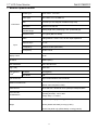
1. Monitor Specifications
Dell E178WFPC
Screen type
Active matrix - TFT LCD
Panel Type
LM171WX3-TLA1 KR ZBD LPL
Size
17 inches (17-inch diagonal viewable image size)
Pixel pitch
0.255 mm x 0.255 mm
Viewable angle
Viewing angle 160° (vertical) typ, 150° (horizontal) typ
Response time
8 ms typical (Black to White)
Video
Analog RGB: 0.7 Volts +/-5%, 75 ohm input impedance
Separate Sync
H/V TTL
H-Frequency
30 kHz to 83 kHz (automatic)
V-Frequency
50 Hz to 75 Hz
LCD Panel
Input
Display Colors
16.7M
Dot Clock
135MHz (Max.)
Max. Resolution
1440 x 900 at 60 Hz
Plug & Play
VESA DDC
EPA ENERGY
STAR®
ON Mode
34 W (typical)
OFF Mode
<1W
Input Connector
Maximum Screen Size
15-pin D-subminiature, blue connector
Horizontal : 367.2 mm(14.46 inches)
Vertical: 229.5 mm(9.04 inches)
Power Source
100 to 240 VAC / 50-60 Hz / 0.6A (100V)& 0.35A(240V)Max.
Environmental
Considerations
Operating Temp: 5° to 35°C
Operating Humidity: 10% to 80%
Storage Temp.: 0° to 60°C
Weight with packaging: 4.85 kg (10.685 lb)
Weight
Monitor (Stand and Head): 3.60 kg (7.93 lb)
Monitor Flat panel only (VESA Mode): 2.70 kg (5.95 lb)
4
17" LCD Color Monitor
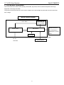
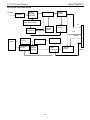
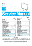
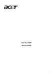
2. LCD Monitor Description
Dell E178WFPC
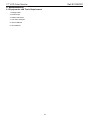
The LCD monitor will contain a main board, power board, key board, which house the flat panel control logic,
brightness control logic and DDC.
The power board will provide AC to DC Inverter voltage to drive the backlight of panel and the main board chips
each voltage.
Monitor Block Diagram
Flat Panel and
CCFL Drive.
CCFL backlight
Power board
RS232 Connector
Main Board
For white balance
adjustment in factory
mode
Key board
Video signal, DDC
AC-IN
Host Computer
100-240V
5
17" LCD Color Monitor
3. Operation instructions
Dell E178WFPC
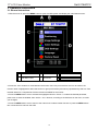
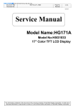
3.1 General Instructions
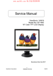
1. With the menu off, press the MENU button to open the OSD system and display the main features menu.
A
Function icons
B
Main Menu
D
Sub-Menu name
E
Resolution
C Menu icon
2. Press the - and + buttons to move between the function icons. As you move from one icon to another, the
function name is highlighted to reflect the function or group of functions (sub-menus) represented by that icon. See
the table below for a complete list of all the functions available for the monitor.
3. Press the MENU button once to activate the highlighted function. Press -/+ to select the desired parameter,
press menu to enter the slidebar, then use the - and + buttons, according to the indicators on the menu, to make
your changes.
4. Press the MENU button once to return to the main menu to select another function or press the MENU button
two or three times to exit from the OSD.
6
17" LCD Color Monitor
Dell E178WFPC
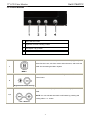
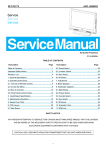
3.2 Control Buttons
1
Menu selection button
2
Brightness Contrast / Down(-) button
3
Auto-Adjust / Up(+) button
4
Power On/Off button with LED indicator
The 'MENU' button is used to open the on-screen display (OSD),
select function icons, exit from menus and sub-menus, and to exit the
OSD. See Accessing the Menu System
1
MENU
Use this button for direct access to the 'Brightness' and 'Contrast'
control menu.
2
Brightness/Contrast Hot Key
Use these buttons to adjust (decrease/increase ranges) items in the
OSD.
2,3
NOTE: You can activate automatic scroll feature by pressing and
holding either + or - button.
- and + buttons
7
17" LCD Color Monitor
Dell E178WFPC
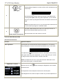
Use this button to activate automatic setup and adjustment. The
following dialog will appear on screen as the monitor self-adjusts to the
current input:
Auto Adjust
Auto Adjust In Progress
3
Auto Adjustment
button allows the monitor to self-adjust to the
incoming video signal. After using 'Auto Adjustment', you can further
tune your monitor by using the 'Pixel Clock' and 'Phase' controls in the
OSD.
NOTE: Auto Adjust will not occur if you press the button while there are
no active video input signals, or attached cables.
The green LED indicates the monitor is on and fully functional. An
amber LED indicates DPMS power save mode.
4
Power Button and Indicator
The Power button turns the monitor on and off.
On Screen Menu/Display (OSD)
Direct-Access Functions
Function
Adjustment Method
Auto adjustment
Use this button to activate automatic setup and adjustment. The following
dialog will appear on screen as the monitor self-adjusts to the current input:
Auto Adjust In Progress
Auto Adjustment
button allows the monitor to self-adjust to the incoming
video signal. After using 'Auto Adjustment', you can further tune your monitor
by using the 'Pixel Clock' and 'Phase' controls in the OSD.
NOTE: Auto Adjust will not occur if you press the button while there are no
active video input signals, or attached cables.
Brightness / Contrast
With the menu off, press
button to display the 'Brightness' and 'Contrast'
adjustment menu.
The 'Brightness' function adjusts the luminance of the flat panel.
Adjust 'Brightness' first, and then adjust 'Contrast' only if further adjustment is
8
17" LCD Color Monitor
Dell E178WFPC
necessary.
"+" increase 'brightness'
" - "decrease 'brightness'
The 'Contrast' function adjusts the degree of difference between darkness and
lightness on the display screen.
"+" increase the 'contrast'
"-" decrease the 'contrast'
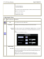
3.3 Adjusting the Picture
Icon
Menu and Submenus
Description
This is used to exit out of the Main Menu.
Exit
Positioning:
'Positioning' moves the viewing area around on the monitor screen.
Horizontal When making changes to either the Horizontal or Vertical settings, no changes
Vertical occur to the size of the viewing area; the image gets shifted based on what you
select.
Minimum is '0' (-). Maximum is '100' (+).
Image settings:
Auto Adjust Even though your computer system can recognize your new flat panel monitor on
startup, the 'Auto Adjustment' function will optimize the display settings for use
with your particular setup.
NOTE: In most cases, 'Auto Adjust' produces the best image for your
configuration; you can directly access this function via Auto Adjustment
9
17" LCD Color Monitor
Dell E178WFPC
hotkey.
Pixel Clock
The Phase and Pixel Clock adjustments allow you to more closely adjust your
monitor to your preference. Select Image Settings in the main OSD to access
these settings.
Use the - and + buttons to adjust interference. Minimum: 0 ~ Maximum: 100
Phase
If satisfactory results are not obtained using the Phase adjustment, use the Pixel
Clock adjustment and then use Phase again.
NOTE: This function may change the width of the display image. Use the
'Horizontal' function of the 'Position' menu to center the display image on the
screen.
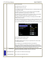
Color Settings
Adjusts the color temperature and saturation.
Color Settings adjust the color temperature.
Color Settings has the following options: Color Management :
Color Settings Mode : You can choose between a Graphics and a Video mode. If
your computer is connected to your monitor, choose Video.
Color Presets: You can choose different color presets for different viewing
modes.
10
17" LCD Color Monitor
Dell E178WFPC
As soon as choose Graphics, you can choose Normal Preset, Red Preset, Blue
Preset or User Preset.
Select Red Preset for a warm color.
Select Blue Preset for a cool color.
You can adjust the monitor color using User Preset, R, G, B.Normal Preset mean
color temperature 6500K.
Select Blue Preset for a bluish tint. This color setting is used for text based
applications (spreadsheets, programming, text editors, etc.).
Select Red Preset for a reddish tint.This color setting is used for color-intensive
applications (photograph image editing, multimedia, movies, etc.).
Select Normal Preset for default color settings. This setting is also the “sRGB”
standard default color space.
User Preset: Use the plus and minus buttons to increase or decrease each of the
three colors (R, G, B) independently, in single digit increments, from 0 to 100.
There are three video modes: Theater Preset, Sports Preset, and Nature Preset.
Select Theater Preset for playing a movie.
Select Sports Preset for viewing sports.
Select Nature Preset for general viewing. For general picture or web or watch
TV, choose Nature Preset.
User can adjust the Hue (Tint)/Saturation based on the preference.
NOTE: 'Color temperature' is a measure of the 'warmth' of the image colors
(red/green/blue). The two available presets ('Blue' and 'Red') favor blue and red
accordingly. Select each one to see how each range suits your eye; or utilize the
'User Preset' option to customize the color settings to your exact choice.
OSD Settings:
Horizontal Position
Vertical Position
Each time the OSD opens, it displays in the same location on the screen. 'OSD
Settings' (horizontal/vertical) provides control over this location.
- and + buttons move OSD to the left and right.
- and + buttons move OSD down and up.
11
17" LCD Color Monitor
OSD Hold Time
OSD Lock
Dell E178WFPC
The OSD stays active for as long as it is in use.
'OSD Hold Time': Sets the length of time the OSD will remain active after the last
time you pressed a button.
Use the - and + buttons to adjust the slider in 5 second increments, from 5 to 60
seconds
NOTE: Default 'OSD hold time' is 20 seconds.
Controls user access to adjustments. When 'Yes' (+) is selected, no user
adjustments are allowed. All buttons, except Menu, are locked.
All buttons can be locked or unlocked. Press the 'Menu' button for over 15
seconds to unlock the OSD menu.
NOTE: When the OSD is locked, pressing the 'Menu' button will take the user
directly to the 'OSD settings' menu, with 'OSD Lock' preselected on entry. Select
'No'(-) to unlock and allow user access to all applicable settings.
Language
Language sets the OSD to display in one of five languages (English, Español,
Français, Deutsch, and Japanese).
NOTE: The language chosen affects only the language of the OSD. It has no
effect on any software running on the computer.
Factory Reset: Factory Reset returns the settings to the factory preset values for the selected
group of functions.
12
17" LCD Color Monitor
Dell E178WFPC
Exit is used to exit out of Factory Reset menu.
For All settings, all user adjustable settings are reset at one time except
Language settings.
IR —
This feature will help reduce minor cases of image retention.
Enable LCD Conditioning: If an image appears to be stuck on the monitor,
select LCD Conditioning to help eliminate any image retention. Using the LCD
Conditioning feature may take several hours. Severe cases of image retention
are known as burn-in, the LCD Conditioning feature does not remove burn-in.
NOTE: Use LCD Conditioning only when you experience a problem with image
retention.
Below warning message appears once user select “Enable LCD Conditioning”:
NOTE: Press any button on the monitor to terminate LCD Conditioning at any
time.
DDC/CI (Display Data Channel/Command Interface) allows you to adjust the
monitor parameters (brightness, color, balance, etc.) via software applications
on your PC.
13
17" LCD Color Monitor
Dell E178WFPC
Select Disable to disable this feature.
For best user experience and optimum performance of your monitor, keep this
feature enabled.
NOTE: If user select 'disable' for DDC/CI, the warning message will appear on
screen. Then user can select Yes or No according to need.
Automatic Save
With the OSD open, if you make an adjustment and then either proceed to another menu, or exit the OSD, the
monitor automatically saves any adjustments you have made. If you make an adjustment and then wait for the
OSD to disappear the adjustment will also be saved.
14
17" LCD Color Monitor
Dell E178WFPC
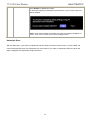
OSD Warning Messages
A warning message may appear on the screen indicating that the monitor is out of sync.
Cannot Display This Video Mode
Optimum resolution 1440 x 900 60Hz
This means that the monitor cannot synchronize with the signal that it is receiving from the computer. Either the
signal is too high or too low for the monitor to use. See Specifications for the Horizontal and Vertical frequency
ranges addressable by this monitor. Recommended mode is 1440 X 900 @ 60Hz.
NOTE: The floating 'Dell - self-test Feature Check' dialog appears on the screen if the monitor cannot sense a
video signal.
Occasionally, no warning message appears, but the screen is blank. This could also indicate that the monitor is
not synchronizing with the computer. See Troubleshooting for more information.
15
17" LCD Color Monitor
4. Input/Output Specification
Dell E178WFPC
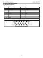
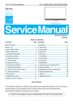
4.1 Input Signal Connector
VGA Connector:
Pin No.
Description
Pin No.
Description
1
Video-Red
9
Computer 5V/3.3V
2
Video-Green
10
GND-sync
3
Video-Blue
11
GND
4
GND
12
DDC data
5
Self-test
13
H-sync
6
GND-R
14
V-sync
7
GND-G
15
DDC clock
8
GND-B
VGA Connector layout
16
17" LCD Color Monitor
Dell E178WFPC
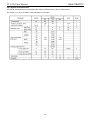
4.2 Factory Preset Display Modes
Display Mode
Horizontal
Vertical
Pixel
Sync Polarity
Frequency
Frequency
Clock
(kHz)
(Hz)
(MHz)
(Horizontal/Vertical)
VGA, 720 x 400
31.5
70.1
28.3
-/+
VGA, 640 x 480
31.5
60.0
25.2
-/-
VESA, 640 x 480
37.5
75.0
31.5
-/-
VESA, 800 x 600
37.9
60.3
40.0
+/+
VESA, 800 x 600
46.9
75.0
49.5
-/+
VESA, 1024 x 768
48.4
60.0
65.0
-/-
VESA, 1024 x 768
60.0
75.0
78.8
+/+
VESA, 1152 x 864
67.5
75.0
108.0
+/+
VESA, 1280 x 1024
64.0
60.0
108.0
+/+
VESA, 1280 x 1024
80.0
75.0
135.0
+/+
VESA, 1440 x 900
55.935
60.0
106.5
-/+
4.3 Power Supply Requirements
A/C Line voltage range
: 100 V ~ 240 V± 10 %
A/C Line frequency range
: 50 ± 3Hz, 60 ± 3Hz
Input Voltage transients
: 280 volts AC for 10 sec @40℃
Current
: 0.6A max. at 100V, 0.35A max. at 240 V
Peak surge current
Leakage current
Power line surge
: < 60A peak at 240 VAC and cold starting
: < 30A peak at 120VAC and cold starting
: < 3.5mA
: No advance effects (no loss of information or defect)
with a maximum of 1 half-wave missing per second
17
17" LCD Color Monitor
Dell E178WFPC
4.4 Panel Specification
HSD170MGW1-B00 ZBD NJ HSD
4.4.1 Display Characteristics
Active Screen Size
17.1 inches(43.3019cm) diagonal (Aspect ratio 16:10)
Outline Dimension
389.2(H)x254.5(V)x11.5(D) mm (Typ.)
Pixel Pitch
0.255mm x 0.255mm
Pixel Format
1440 horiz. By 900 vert. Pixels RGB strip arrangement
Color Depth
16.7M colors
Luminance, White
250 cd/m2 (Center 1 points Typ.)
Viewing Angle (CR>10) R/L 160(Typ.), U/D 160(Typ)
Power Consumption
Weight
Total
12.92 Watt(Typ.) (2.6 Watt@VLCD, 10.32 Watt@250cd/[Lamp=8mA])
1360 g (Typ.)
Display Operating Mode Transmissive mode, normally white
Surface Treatment
Hard coating(3H),Anti-glare treatment of the front polarizer
18
17" LCD Color Monitor
Dell E178WFPC
4.4.2 Optical Characteristics
The optical characteristics are measured under stable conditions at 25℃ (Room Temperature):
Ta= 25±2°C, VLCD=5.0V, fV=60Hz, Dclk=106.5MHz, ILamp=8mA
19
17" LCD Color Monitor
Dell E178WFPC
4.5 Definition of Pixel Defects
4.5.1 Inspection environment conditions:
◆ Room temperature: 20 ~ 25 C
◆ Humidity: 65 ± 5% RH.
◆ Illumination: Fluorescent light (Day-Light Type) display surface illumination to be 300 ~ 700 Lux. (standard
500Lux.)
◆ To be a distance about 35±5 cm in front of LCD unit, viewing line should be perpendicular to the surface of the
module judge the visual appearance with human’s eyes. (Stand up the panel for judge and ±30° viewing edge
will be allowed)
◆ Take off the protection film of polarizer while judging the display area.
◆ If there is any question while judging, check the panel again in operating mode.
4.5.2. Display Defect Requirements
1. Max. 0 red, green or blue bright dots (sub-pixels), max. 0 green dots, max. 0 joined bright dot, min. distance
between 2 bright dots: 10 mm. Bright dots are tested with full screen black pattern (R.G.B. = 0, 0, 0)
2. Max. 4 black dots. Max. 2 joined (2 adjacent) black dots, no defect with 3 adjacent black dots. Min. distance
between 2 black dots: 10mm.Black dots are tested with full screen white (R.G.B. = 255,255,255)/ red (R.G.B. = 255,
0, 0)/green (R.G.B. = 0, 255, 0)/blue (R.G.B. = 0, 0,255) pattern.
3. Total amount of Dot Defects are 5 Max. (Including bright and dark dot defects)
20
17" LCD Color Monitor
5. Block Diagram
Dell E178WFPC
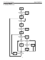
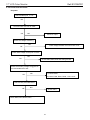
5.1 Software Flow Chart
1
Y
2
3
N
4
N
5
Y
6
N
7
8
Y
9
N
10
11
Y
N
12
13
Y
Y
14
15
Y
17
18
N
N
19
Y
21
N
16
17" LCD Color Monitor
Dell E178WFPC
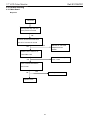
1) MCU Initializes.
2) Is the EEprom blank?
3) Program the EEprom by default values.
4) Get the PWM value of brightness from EEprom.
5) Is the power key pressed?
6) Clear all global flags.
7) Are the AUTO and SELECT keys pressed?
8) Enter factory mode.
9) Save the power key status into EEprom. Turn on the LED and set it to green color. Scalar initializes.
10) In standby mode?
11) Update the lifetime of back light.
12) Check the analog port, are there any signals coming?
13) Does the scalar send out an interrupt request?
14) Wake up the scalar.
15) Are there any signals coming from analog port?
16) Display "No connection Check Signal Cable" message. And go into standby mode after the message
disappears.
17) Program the scalar to be able to show the coming mode.
18) Process the OSD display.
19) Read the keyboard. Is the power key pressed?
22
17" LCD Color Monitor
Dell E178WFPC
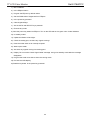
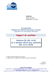
5.2 Electrical Block Diagram
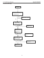
5.2.1 Main Board
LCD Interface
Crystal
14.318MHZ
(CN301)
(X201)
Flash Memory
SST25LF020A-33-4C-SAE
Scalar TSUM16AWR-LF-1
(U203)
(Include MCU, ADC, OSD)
(U401)
R
RXD
TXD
G
B
OSD Control Interface
D-Sub
(CN201)
Connector
(CN101)
23
H
V
DB15_SDA,
DB15_SCL
EEPROM M24C02
(U703)
17" LCD Color Monitor
Dell E178WFPC
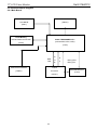
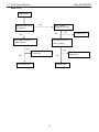
5.2.2 Inverter and Power Board
AC input
Bridge
Rectifier
and Filter
EMI filter
Transformer
Rectifier
diodes
Start Circuit
R904, R932, R933
Over
Voltage
Protect
PWM
Control IC
5V
Feedback
Circuit
12V
ON/OFF
Lamp
Output
Circuit
Feedback
Circuit
MOSFET
Transformer
Over
Voltage
Protect
PWM
Control IC
ON/OFF
Control
DIM
24
CN902
17" LCD Color Monitor
6. Mechanical Instructions
Dell E178WFPC
Tools: 2 Power screwdrivers (φ=5mm,L=60mm); 1 small cross screwdriver; turnbuckle driver;
Setting: Power screwdriver torque A=11 kgF. Cm; torque B=6 kgF. Cm
Note: Firstly, put the monitor on a soft, flat and clean surface, wear gloves.
Fig
Remark
Remove stand:
1. Rotate the stand to allow access
to the stand release button.
2. Press the Stand release button
and lift up the Stand and away from
the monitor.
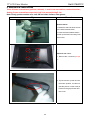
Remove rear cover :
1. Remove the 4 screws by torque
A
2. Pry the monitor up then find out
the hooks’ position, use the tool
(like the picture or other card) to
insert into the gap of bezel and
rear cover.
25
17" LCD Color Monitor
Dell E178WFPC
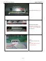
3. Turn over the monitor as the Fig,
hold the rear cover, and then
slightly remove it.
Remove the small shield:
Remove the small shield as the
arrowhead direction, disconnects
the keyboard connector, and then
remove the bezel.
Remove the shield :
1. Remove the screw by Torque B
or by manual and remove the small
shield
26
17" LCD Color Monitor
Dell E178WFPC
Remove the two screws by Torque
B.
Remove the main frame:
Remove the 4 screws by manual
or torque = 3kgF.Cm and remove
the main frame
Install:
Fix the FFC connector as the
figure.
Note: Make LVDS connector’s
metal side adown .
FFC Cable
27
17" LCD Color Monitor
Dell E178WFPC
Remove the Boards:
Remove the seven screws by
Torque B and remove the Power
Board and Main Board.
Screw pillar
Ground cable
Install:
The ground cable should be laid
above the other two cables and
below the screw pillar.
Install:
Note: The pins can’t touch the blue
and purple lines.
28
17" LCD Color Monitor
Dell E178WFPC
The end
45℃
Install:
The angle between CCFL line and
vertical direction should be 45
degree.
29
17" LCD Color Monitor
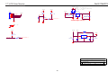
7. Schematic Diagram
Dell E178WFPC
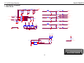
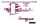
7.1 Main Board
2
2
R101 0R05 1/16W
R106
2K2 1/16W
DSUB_H
DSUB_V
FB102
VGA_B+
C102 C103
22pF
2
2
1
BEAD
2
R104
R107
22pF
VGA_B-
C101
0.047uF
DSUB_B+
2
100R 1/16W
C105
0.047uF
DSUB_B-
2
C106
0.047uF
DSUB_SOG
2
100R 1/16W
C107
0.047uF
DSUB_G+
2
R114
100R 1/16W
C109
0.047uF
DSUB_G-
2
R115
100R 1/16W
C110
0.047uF
DSUB_R+
2
100R 1/16W
C113
0.047uF
DSUB_R-
2
R108
16
CN101
100R 1/16W
C104
5pF/50V
75R 1/16W
1
1
ZD101
UDZS5.6B
2K2 1/16W
R105
ZD102
UDZS5.6B
R102 100R 1/16W
R103 100R 1/16W
2
2
BEAD
2
1
75R 1/16W
C108
5pF/50V
FB101
D104
BAV99
VGA_R+
CMVCC
1
BEAD
2
R116
C112
0.1uF 16V
1
D103
BAV99
390Ω 1/16W
R111
VGA_G-
3 VGA_B+
3
D102
BAV99
1
R112
DB15
2
GND POWER
VGA_G+
ZD104
UDZS5.6B
2
11
ZD106
UDZS5.6B
17
ZD105
UDZS5.6B
R109
FB103
ZD103
UDZS5.6B
VGA_G+
12
2
2
100R 1/16W
DDC1_SDA
R113
1
DDC1_SDA
1
2
VGA_BVGA_B+
VGA_GVGA_G+
VGA_RVGA_R+
3
13
1
14
VGA_PLUG
DSUB_5V
DSUB_5V
1
10
5
9
4
8
3
7
2
6
1
15
2
DDC1_SCL 100R 1/16W
R110
VGA_R+
DDC1_SCL
1
2
75R 1/16W
VGA_R-
C111
5pF/50V
R117
DGND
CMVCC
DSUB_5V
VCC3.3
BAV70
D105
R137
10K 1/16W
0.22uF16V
C414 U703
1
2 A0
3 A1
4 A2
GND
VCC
WP
SCL
SDA
8
7
6
5
R120
4K7 1/16W
R413
10K 1/16W
DDC1_SCL
DDC1_SDA
R121
4K7 1/16W
VGA_PLUG
DET_CABLE
2
EDID_WP 3
M24C02-WMN6TP
TPV (Top Victory) Electronics Co., Ltd.
Title
Size
B
Date:
30
INPUT
Document Number
Rev
G2659-1-DEL-X-1-070530
Monday , June 04, 2007
Sheet
1
of
5
A
17" LCD Color Monitor
Dell E178WFPC
AVDD VDDP
VDDC
VDDP
1
1
1
1
1
1
1
1
1
1
1
DSUB_R+
DSUB_RDSUB_G+
DSUB_GDSUB_SOG
DSUB_B+
DSUB_BDSUB_H
DSUB_V
DDC1_SDA
DDC1_SCL
RIN0P
RIN0M
GIN0P
GIN0M
SOGIN0
BIN0P
BIN0M
HSY NC0
VSY NC0
DDCA_SDA/RS232_TX
DDCA_SCL/rs232_RX
30
53
VDDC
VDDC
51
VDDP
13
12
10
9
11
8
7
16
17
18
19
AVDD_ADC
6
VCC3.3
1
VCTRL
LVA3P
LVA3M
LVA2P
LVA2M
LVA1P
LVA1M
LVA0P
LVA0M
FB203
VCC3.3
33
34
PA0
PA1
35
36
37
38
39
40
PA4
PA5
PA6
PA7
PA8
PA9
C202
VCC1.8
4
AVDD
R204 390Ω 1/16W
15
VCC3.3
REXT
REFP
TSUM16AWR
PB0
PB1
PB2
PB3
PB4
PB5
PB6
PB7
PB8
PB9
PB[0..9]
PA[0..9]
3
PB[0..9]
3
VDDC
Q406
2N3904S-RTK/PS
R414
R210
10K 1/16W
U203
1
2
WP 3
4
CE# VDD
SO HOLD#
WP# SCK
VSS
SI
8
7
6
5
21
22
23
24
R207
SST25LF020A-33-4C-SAE
100R 1/16W
28
SDO
SCZ
SCK
SDI
LVDS
GPIO_P12
PWM1/GPIO_P25
RSTN
GPIO_P00/SAR1
GPIO_P01/SAR2
GPIO_P27/PWM1
C220
+
R219
100K 1/16W
33pF
C221
2
R201
0R05 1/16W
1
RST
GPIO_P06
GPIO_P07
PWM0/GPIO_P26
GPIO_P13
GPIO_P14
XIN
20
27
R232
R230
14.318MHz
2
10K 1/16W
100R 1/16W
55
56
57
58
59
60
61
62
63
64
10K 1/16W
C415
VCC3.3
CMVCC
100R 1/16W
100R 1/16W
R217
R218
4K7 1/16W
4K7 1/16W
R220
NC100R 1/16W
R221
NC
R222
KEY 1
KEY 2
R209
10K 1/16W
PMBS3906
Q202
10K 1/16W
4
Mute
4
POWER_KEY #
R223 10K 1/16W
R212 LED_ORANGE
620R OHM 1/16W 5%
070522
Q203
PMBS3906
R216
LED_GRN/BLUE
620R OHM 1/16W 5%
C219
0.1uF 16V
Volume#
R205
10K 1/16W
R208
6K8 1/16W
R211
R213
R214
VCC3.3
0.1uF 16V
PANEL_ID#
on_BACKLIGHT 4
adj_BACKLIGHT 4
X201
C222
C212
0.1uF 16V
VCC3.3
XOUT
33pF
MODE[0]
MODE[1]
26
25
R215
100R 1/16W
PPWR_ON#
DET_CABLE
3
1
GND
GND
GND
GPIO_P10/I2C_MCL
GPIO_P11/I2C_MDA
31
32
3
5
29
4.7uF16V
1
CMVCC
54
GPIO_P15/PWM0
PWM2/GPIO_P24
C211
0.1uF 16V
+
4.7uF16V
EDID_WP 3
C201
0.1uF
14 16V
REFM
C218
0.1uF 16V
C207
0.1uF 16V
VCC1.8
C209
PA[0..9]
LVB3P
LVB3M
LVBCKP
LVBCKM
LVB2P
LVB2M
LVB1P
LVB1M
LVB0P
LVB0M
C203
0.1uF 16V
+
4.7uF16V
4
41
42
43
44
45
46
47
48
49
50
AVDD
600 OHM
52
R226
10K 1/16W
R227
10K 1/16W
VCC3.3
R228
3.9KΩ 1/16W
R229
3.9KΩ 1/16W
CN201
POWER_KEY #
KEY _LEFT
KEY _RIGHT
R234
KEY _AUTO
KEY 1
KEY 2
R236
R233 1K 1/16W
2KΩ 1/16W
R235 1K 1/16W
NC
3/12
LED_ORANGE
LED_GRN/BLUE
C228
0.1uF 16V
C226
0.001uF
C225
C224 0.001uF
C227
0.001uF
0.001uF
C223
0.001uF
1
2
3
4
5
6
7
8
C229
0.1uF 16V
CONN
070516
TPV (Top Victory) Electronics Co., Ltd.
Title
Size
C
Date:
31
SCALAR
Document Number
Rev
G2659-1-DEL-X-1-070530
Monday , June 04, 2007
Sheet
2
of
5
A
17" LCD Color Monitor
2
PA[0..9]
Dell E178WFPC
PA[0..9]
PANEL_VCC
CN301
PA0 LVA3P
PA1 LVA3M
PA4
PA5
PA6
PA7
PA8
PA9
LVA2P
LVA2M
LVA1P
LVA1M
LVA0P
LVA0M
C302
0.1uF 16V
R302
330R 1/8W 5%
PA0
PA1
PB2
PB3
PA4
PA5
LVA3P
LVA3M
LVBCKP
LVBCKM
LVA2P
LVA2M
PA6 LVA1P
PA7 LVA1M
2
PB[0..9]
PB[0..9]
PB0
PB1
PB2
PB3
PB4
PB5
PB6
PB7
PB8
PB9
LVB3P
LVB3M
LVBCKP
LVBCKM
LVB2P
LVB2M
LVB1P
LVB1M
LVB0P
LVB0M
PA8
PA9
PB0
PB1
PB2
PB3
LVA0P
LVA0M
LVB3P
LVB3M
LVBCKP
LVBCKM
PB4
PB5
PB6
PB7
PB8
PB9
LVB2P
LVB2M
LVB1P
LVB1M
LVB0P
LVB0M
1
2
3
4
5
6
7
8
9
10
11
12
13
14
15
16
17
18
19
20
21
22
23
24
25
26
27
28
29
30
CONN
3D
CMVCC
R303
4K7 1/16W
2006-11-7 Add pull up 4K7 to MVCC
2
PPWR_ON#
PPWR_ON#
1
G
AO3401L
C301
0.1uF 16V
R301
10K 1/16W
R304
Q301
100K 1/16W
PMBS3906
2
S
PANEL_VCC
Q302
AO3401
FB301
120Ω
+
C303
100uF/16V
TPV (Top Victory) Electronics Co., Ltd.
Title
Size
B
Date:
32
OUTPUT
Document Number
Rev
G2659-1-DEL-X-1-070530
Monday , June 04, 2007
Sheet
3
of
A
5
17" LCD Color Monitor
Dell E178WFPC
VCC3.3
VCC3.3
R401
CMVCC
CMVCC
CMVCC
BKLT-VBRI
BKLT-EN
10K 1/16W
R402
10K 1/16W
3.3Ω 2W
C403
C412 100uF/16V
0.1uF 16V
BKLT-EN
VCC1.8
BAT54C
D106
U702
MVCC
R403
3
+
VI
VO
2
C402
C413100uF/16V
0.1uF 16V
C406
NC
CONN
Q403
PMBS3904
1
1
2
3
4
5
6
GND
VCC3.3
CN401
3/16
BAT54C : IF 10mA,VF=0.4V
BAV70 : IF 10mA,VF=0.855V(drop
voltage too much)
R404
4K7 1/16W
+
on_BACKLIGHT 2
*12/28 change to LDO due to
internal ripple too big
DGND
1,2,3
VCC3.3
CMVCC
MVCC
FB402
NC
R405
12K 1/16W
R406
1K 1/16W
VIN
VOUT
2
VSS
3
adj_BACKLIGHT 2
C407
100uF/16V
+
C409
0.1uF 16V
AP1117E33LA
C401
1
BKLT-VBRI
VCC3.3
U701
+
C408
100uF/16V
0.1uF 16V
TPV (Top Victory) Electronics Co., Ltd.
Title
Size
B
Date:
33
Power
Document Number
Rev
G2659-1-DEL-X-1-070530
Monday , June 04, 2007
Sheet
4
of
5
A
17" LCD Color Monitor
Dell E178WFPC
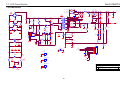
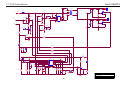
7.2 Power Board
C912
0.001uF
100 1/4W R920
C922
470uF/25V +
+
2
!
1
-
T901
1
C908
22uF/50V
ZD905
RLZ18B
LD7552BPS
100K 1/8W
R961 100 1/4W
C929
0.001uF
8
3
12
+
C939
1000uF/16V
+ C940
1000uF/16V
+5V
0
+
C915
470uF/16V
D907
NC
150R 1/8W
R927
3.6K 1% 1/10W
1
IC903
PC123X2Y FZOF
!
R925
1K 1/8W
FB901
BEAD
C924
0.1uF
C928
0.001uF
C909
470pF/25V
R914
0.47 2W
IC904
KIA431A-AT/P
!
C903
0.47uF/275V
R926
1K 1/10W 1%
R942
1K 1/10W 1%
C925
C921
3300PF/250V
!
!
R902
R901
GND1
GND
680K 1/4W
VAR901
Varistor N.C
!
CONNECTOR
!
F901
FUSE
2
CN901
SOCKET
VOL
1
2
MUTE
HS3
HEAT SINK(Q901)
3
t
!
2.43K 1% 1/10W
1
2
3
4
5
6
7
8
9
10
0.1uF
FG
HS2
HEAT SINK(D906)
NR901
NTCR
+5V
DIM
ON/OFF
C916
1
2
R930
CN902
NC
680K 1/4W
LL4148WP
2
220 1/4W
4.0mH
R900
D916
D915
LL4148WP
R912
!
680K 1/4W
ZD922
RLZ5.1B
ZD921
RLZ13B
1
10K 1/8W
4
!
R940
33K 1/10W
R924
N.C
!
Q901
2SK2645-54MR
R938
F903
L903
1.1uH
R962 100 1/4W
6
1
R939
NC
1000pF
1
2 L901 3
1
D905
31DQ06FC
10
4
R910
10 1/4W
ZD901
NC
1
11
3
5
6
7
8
3
2
R909
5.1 1/4W
D903 LL4148WP
RT
NC
VCC
CS
COMP VCC
GND OUT
R935 100 1/4W
POWER X'FMR
2
4
3
2
1
R915
1
6
4
R907
NC
IC901
!
0.1uF
2
+
C930
R943
1K 1/8W
Q903
PMBS3904
D906
MBFR10150
2
D901
FR103
R933
300K 1/4W
7
1K 1/4W
1K 1/4W
1
C901
0.001uF/250V
!
D900
FR107
ZD906
RLZ22B
5
C918
680uF/25V
C932
100K 2W
R906
NC
C905
0.1uF
9
R908
C906
1500pF/1KV
2
!
7.0mH
R905
NC
R932
300K 1/4W
SG902 NC
3
C902
0.001uF/250V
R904
300K 1/4W
C938
1500pF/1KV
1 L902 2
4
C907
100uF/450V
4
R944
R946
+
C917
680uF/25V
3
+12V
ZD902
RLZ13B
2
4
+
!
SG901 NC
2
3
R941 R945
1K 1/4W
1K 1/4W
1.1uH
1
1
BD901
KBP208G
+
!
L904
100 1/4W R919
2
100 1/4W R918
Title
1
2
1
Size
!
Date:
34
G2545-1-2-X-2-070524
Document Number
Thursday , May 24, 2007
Rev
1
Sheet
1
of
2
17" LCD Color Monitor
Dell E178WFPC
CN801
C839
1000pF
R855
33 1/4W
FB801
F801
1
T801
POWER X'FMR
7
3
4
2
R804
100 1/8W
Q805
PDTC144WK
Q801
PMBS3904
D810
NC
C824
0.1uF
Q802
AM9945N-T1-PF
1
8
S
D
Q808
PDTA144WK
2
ON/OFF
Q804
PMBS3906
1
C825
0.1uF/25V
R839
22R 1/8W
3
4
G
D
S
D
G
D
R856
33 1/4W
7
R817
10K 1/10W
1
R821
1K 1/10W 1%
CONN
C819
0.0022uF
2
3
1
8
R801
1K 1/10W 1%
D801
BAV99
C838
1000pF
6
2
1
5
R828
10K 1/10W
R822
1K 1/10W 1%
2
CN802
CONN
3
C807
0.1uF/25V
C802
470uF/25V +
D805
LL4148WP
C801
15pF/3KV
BEAD
0R05 1/4W
2
+12V
6
1
2
Q811
PMBS3904
DIM
D807
LL4148WP
R811
4.7K 1/10W
Q812
PMBS3906
1
1
D802
BAV99
2
ZD801
RLZ6.8C
R850
22R 1/8W
3
1
Q810
RK7002
3
R814
1K 1/10W 1%
D811
NC
2
D813
LL4148WP
DTC
C823
0.0022uF
R813
1K 1/10W
R827
1K 1/10W 1%
Q806
PMBS3904
R853
68K 1/10W
C835
NC
D817
LL4148WP
R841
68K 1% 1/10W
R851
5.1K 1/10W
C842
0.01uF
R802
91K 1/10W
R829
22R 1/8W
R825
22R 1/8W
R837
47K 1/10W
R830
NC
C822
1uF/25V
D812
LL4148WP
R832
10K 1/10W
R807
10K 1/10W
IC801
1
2
3
4
5
6
7
8
R823
0 1/10W
IN1+
IN1FB
DTC
CT
RT
GND
C1
IN2+
IN2VREF
CONT
VCC
C2
E2
E1
16
15
14
13
12
11
10
9
R818
1K 1/10W 1%
D806
LL4148WP
KA7500CDTF
C821
0.1uF/25V
10K 1/10W
R820
R863
10K 1/10W
R831
1K 1/8W
R810
R865
51K 1% 1/8W
NC
C820
220pF
R861
NC
R864
NC
Q807
NC
R854
NC
R826
1K 1/8W
R824
R803
10M 1/10W
R808
1K 1/10W 1%
1K 1/10W 1%
C817
NC
C845
2.2uF/16V
R862
1M 1/10W 5%
D814
LL4148WP
Q809
RK7002
C846
NC
C834
0.1uF/25V
R835
1M 1/10W 5%
Title
Size
Date:
35
G2545-1-2-X-2-070524
Document Number
Custom 1.0
Thursday , May 24, 2007
Rev
1
Sheet
2
of
2
17" LCD Color Monitor
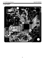
8. PCB Layout
Dell E178WFPC
8.1 Main Board
36
17" LCD Color Monitor
Dell E178WFPC
37
17" LCD Color Monitor
Dell E178WFPC
38
17" LCD Color Monitor
Dell E178WFPC
8.2 Power Board
39
17" LCD Color Monitor
Dell E178WFPC
40
17" LCD Color Monitor
Dell E178WFPC
41
17" LCD Color Monitor
Dell E178WFPC
8.3 Key Board
42
17" LCD Color Monitor
9. Maintainability
Dell E178WFPC
9.1 Equipments and Tools Requirement
1. Voltage meter
2. Oscilloscope
3. Pattern Generator
4. LCD Color Analyzer
5. Service Manual
6. User Manual
43
17" LCD Color Monitor
Dell E178WFPC
9.2 Trouble shooting
9.2.1 Main Board
No power
No power
Press power key and look
if the picture is normal
OK
Please reinsert and make sure
the AC of 100-240 is normal
NG
OK
Reinsert or check the
Adapter/Inverter
section
Measure U701 PIN2=3.3V
U702 PIN2=1.8V
OK
Check CN401 or replace
U701, U702
NG
X201 oscillate waveforms
are normal
OK
NG
Replace X201
Replace U401
44
17" LCD Color Monitor
Dell E178WFPC
No picture (LED orange)
No picture
Measure U701 PIN2=3.3V
U702 PIN2=1.8V
NG
Replace U701, U702
OK
X201 oscillate
waveform is normal
NG
Replace X201
OK
Whether the reset
of the Scalar IC is
useful?
OK
Check C407, C227,
NG
R219
Check HS/VS from
Replace
U401
CN101
is normal
NG
Check Correspondent
component
OK
Replace U401
45
17" LCD Color Monitor
Dell E178WFPC
White screen
White screen
NG
Measure Q301 base
X201 oscillate
waveform is normal
is low level?
OK
OK
NG
Check Q302 is broken or
Check reset circuit of
CN301 solder?
U401 is normal
NG
NG
Check Correspondent
component.
Check Correspondent
component.
OK
OK
Replace PANEL
Replace U401
46
Replace X201
17" LCD Color Monitor
Dell E178WFPC
9.2.2 Power/Inverter Board
No power
Check CN902 pin3, 4 = 5V
NG
Check AC line volt 110V or 220V
OK
NG
Check AC input
Check the voltage of C907(+)
NG
Check bridge rectified circuit and F901 circut
OK
Check start voltage for the pin3 of IC901
NG
OK
Check R904,R932,R933 and Change IC901
Check the auxiliary voltage is bigger than
10V and smaller than 20V
NG
1) Check IC901
OK
2) Check C909, D901, R909…OVP circuit
Check IC901 pin8 PWM wave
OK
NG
Check IC901
Check D906,L904,ZD902,C922,……
47
17" LCD Color Monitor
Dell E178WFPC
No Backlight
Check F801=12V
OK
NG
Check adapter and F801
Check ON/OFF signal
OK
NG
Check Interface board or main board
Check IC801 PIN12=5V
OK
NG
Change on/off circuit
Check IC801 PIN1 have triangle wave
OK
NG
Change IC801
Check ZD801 has the output of square wave at short time.
OK
NG
Check Q805/Q806
Check the resonant wave of pin2 & pin5 for T801
OK
Check the output of T801
NG
NG
Check Q801/Q811/D810/D811
Change T801
OK
Check connecter & lamp
48
17" LCD Color Monitor
Dell E178WFPC
9.2.3 Keypad Board
OSD is unstable or not working
N
Connect Key Pad Board
Is Key Pad Board connecting normally?
Y
N
Is Button Switch normally?
Replace Button Switch
Y
N
Is Key Pad Board normally?
Replace Key Pad Board
Y
Check Main Board
49
17" LCD Color Monitor
10. White balance, Luminance adjustment
Dell E178WFPC
Approximately 2 Hours should be allowed for warm up before proceeding White-Balance
adjustment.
Before started adjust white balance, please setting the Chroma-7120 MEM. Channel 3 to 65000K colors, MEM.
Channel 3 to 93000K colors, MEM. Channel 3 to 57000K (our 9300 parameter is x=283±30, y=297±30;6500
parameter is x =313±30, y=329±30, Y = 200 ±20 cd/m2, and 5700 parameter is x = 328 ±30, y = 344 ±30.)
How to setting MEM.channel you can reference to Chroma-7120 user guide or simple use “ SC” key and “ NEXT”
key to modify x, y, Y value and use “ID” key to modify the TEXT description Following is the procedure to do
white-balance adjust
Enter into the factory mode:
Press MENU and “+” button during press Power button will activate the factory mode,
Gain adjustment:
Move cursor to “-Factory Setting-” and press MENU key to enter this sub-menu.
Move cursor to “Factory” and press MENU key.
Move cursor to “ Auto Level” and press MENU key to adjust Gain and Offset automatically;
a. Adjust sRGB (65000K) color-temperature
1. Switch the Chroma-7120 to RGB-mode (with press “MODE” button)
2. Switch the MEM. channel to Channel 3 (with up or down arrow on Chroma-7120)
3.The LCD-indicator on Chroma-7120 will show x = 313 ±30, y = 329 ±30, Y = 200 ±20 cd/m2
b. Adjust Color1 (93000K) color-temperature
4. Switch the Chroma-7120 to RGB-mode (with press “MODE” button)
5. Switch the MEM. channel to Channel 3 (with up or down arrow on Chroma-7120)
6. The LCD-indicator on Chroma-7120 will show x = 283 ±30, y = 297 ±30.
c. Adjust Color2 (57000K) color-temperature
7. Switch the Chroma-7120 to RGB-mode (with press “MODE” button)
8. Switch the MEM. channel to Channel 3 (with up or down arrow on Chroma-7120)
9. The LCD-indicator on Chroma-7120 will show x = 328 ±30, y = 344 ±30.
10. Move cursor to “Exit/Save” sub-menu and press MENU key to save adjust value and exit.
Turn the POWER-button off to on to quit from factory mode.
Max Brightness measurement: >230 cd/㎡
Test conditions:
a. Switch to the full white pattern, in user mode main menu:
1. Set <Color Settings> Red, Green, and Blue to the max.
2. Set <Brightness> Brightness, Contrast to the max.
b. The Minimum brightness is: < 40% of Max luminance (max luminance = max contrast + max brightness)
Test conditions:
Set <Brightness> Brightness, Contrast to the min.
50
17" LCD Color Monitor
11. ISP Instruction
Dell E178WFPC
Configure and procedure
It is a windows-based program, which cannot be run in MS-DOS.
System and equipment requirements
(1). An i486 (or above) personal computer or computer or compatible.
(2). Microsoft operation system Window 95/98/2000/XP.
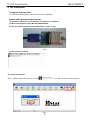
(3). ISP Tool: ISP board/printer cable/VGA cable as shown in Fig.1
Link to Dell
Connect to PC LPT
VGA connector
Fig.1
(4). ISP software checklist
(5). Update the firmware
Step 1: Double click the ISP_Tool v3.772.exe
icon and click Connect, bring up Fig.2
Fig.2
51
17" LCD Color Monitor
Dell E178WFPC
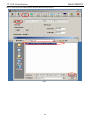
Step 2: Click OK and click Read, select program Bin file, bring up Fig.3
Fig.3
52
17" LCD Color Monitor
Dell E178WFPC
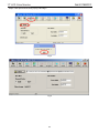
Step3: Click open and OK, bring up Fig.4 and Fig.5
Fig.4
Fig.5
53
17" LCD Color Monitor
Dell E178WFPC
Step 4: Click Auto and Run, bring up Fig.6
Fig.6
Step 5: When appear Verify OK, writer finished as shown Fig.7
Fig.7
54
17" LCD Color Monitor
12. Exploded View
Dell E178WFPC
55
17" LCD Color Monitor
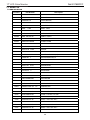
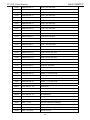
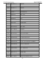
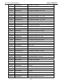
13. BOM List
Dell E178WFPC
T77GMRHKPWDLNN
Location
Part Number
Description
023G3178700 3A
LOGO
026G 800700 6A
S/N LABEL
044G9000 7A
PAPER BOARD
044G9003100
CORNER PAPER
044G9003119
CORNER PAPER
052G
SMALL TAPE
1186
052G6022 1500
SMALL TAPE
085G 702 1
SHIELD WIRE
089G 728LAA 2D
SIGNAL CABLE
089G179S30N501
FFC CABLE
089G402A18NISD
POWER CORD
0M1G 130 6125
SCREW
0M1G1030 6120
SCREW M3X6
0M1G1730 6120
SCREW
0M1G2940 10225 CR3
SCREW
705GQ734168
MAIN FRAME ASS'Y(17")
015G8185 1
HOLDER BRACKET R
015G8186 1
HOLDER BRACKET L
019G 588 3
SPRING -HOLDER
0M1G 130 6120
SCREW M3X6
A20G0007 1
STAND HOLDER
Q15G0212 2
MAINFRAME
750GLG71W3A11Z000D
PANEL LM171WX3-TLA1 KR ZBD LPL
A33G0025 VH 1L
RELEASE BUTTON
CBPC7GMRDLQ1
MAIN BOARD
CN401
033G3802 6B Y
CONN 6PIN 2.0
CN201
033G8019 8T JH
WIRE HARNESS
CN301
033G801930F CH JS
CONNECTOR
040G 457624 1B
LABEL-CPU
040G 45762412B
CBPC LABEL
R402
061G152M339 64
CHIPR 3.3 OHM +-5% 2W
C403
067G305V101 3P
100UF +-20% 16V 105℃
C402
067G305V101 3P
100UF +-20% 16V 105℃
C303
067G305V101 3P
100UF +-20% 16V 105℃
C408
067G305V101 3P
100UF +-20% 16V 105℃
C407
067G305V101 3P
100UF +-20% 16V 105℃
C220
067G305V479 3P
4.7UF 16V 105℃
E089B
E089A
56
17" LCD Color Monitor
Dell E178WFPC
C202
067G305V479 3P
4.7UF 16V 105℃
C209
067G305V479 3P
4.7UF 16V 105℃
CN101
088G 35315F H
D-SUB 15PIN
X201
093G 22 53
CRYSTAL 14.318MHZHC-49US
U401
056G 562548
IC TSUM16AWR-LF-1 MSTAR
U702
056G 563 27
IC AIC1117A-18PYTR-R SOT223
U701
056G 585 4A
AP1117E33LA
U703
056G1133 34
M24C02-WMN6TP
U203
056G1133 81
SST25LF020A-33-4C-SAE
Q403
057G 417 4
PMBS3904/PHILIPS-SMT(04)
Q202
057G 417 6
PMBS3906/PHILIPS-SMT(06)
Q203
057G 417 6
PMBS3906/PHILIPS-SMT(06)
Q301
057G 417 6
PMBS3906/PHILIPS-SMT(06)
Q406
057G 417 12 T
KEC 2N3904S-RTK/PS
Q302
057G 763 1
A03401 SOT23 BY AOS(A1)
R101
061G0402000
RST CHIPR 0 OHM +-5% 1/16W
R201
061G0402000
RST CHIPR 0 OHM +-5% 1/16W
R213
061G0402101
RST CHIPR 100 OHM +-5% 1/16W
R207
061G0402101
RST CHIPR 100 OHM +-5% 1/16W
R117
061G0402101
RST CHIPR 100 OHM +-5% 1/16W
R115
061G0402101
RST CHIPR 100 OHM +-5% 1/16W
R114
061G0402101
RST CHIPR 100 OHM +-5% 1/16W
R113
061G0402101
RST CHIPR 100 OHM +-5% 1/16W
R111
061G0402101
RST CHIPR 100 OHM +-5% 1/16W
R110
061G0402101
RST CHIPR 100 OHM +-5% 1/16W
R108
061G0402101
RST CHIPR 100 OHM +-5% 1/16W
R104
061G0402101
RST CHIPR 100 OHM +-5% 1/16W
R103
061G0402101
RST CHIPR 100 OHM +-5% 1/16W
R102
061G0402101
RST CHIPR 100 OHM +-5% 1/16W
R214
061G0402101
RST CHIPR 100 OHM +-5% 1/16W
R215
061G0402101
RST CHIPR 100 OHM +-5% 1/16W
R222
061G0402101
RST CHIPR 100 OHM +-5% 1/16W
R230
061G0402101
RST CHIPR 100 OHM +-5% 1/16W
R406
061G0402102
RST CHIPR 1 KOHM +-5% 1/16W
R235
061G0402102
RST CHIPR 1 KOHM +-5% 1/16W
R233
061G0402102
RST CHIPR 1 KOHM +-5% 1/16W
R414
061G0402103
RST CHIPR 10 KOHM +-5% 1/16W
R413
061G0402103
RST CHIPR 10 KOHM +-5% 1/16W
R403
061G0402103
RST CHIPR 10 KOHM +-5% 1/16W
R401
061G0402103
RST CHIPR 10 KOHM +-5% 1/16W
57
17" LCD Color Monitor
Dell E178WFPC
R301
061G0402103
RST CHIPR 10 KOHM +-5% 1/16W
R232
061G0402103
RST CHIPR 10 KOHM +-5% 1/16W
R227
061G0402103
RST CHIPR 10 KOHM +-5% 1/16W
R226
061G0402103
RST CHIPR 10 KOHM +-5% 1/16W
R223
061G0402103
RST CHIPR 10 KOHM +-5% 1/16W
R211
061G0402103
RST CHIPR 10 KOHM +-5% 1/16W
R210
061G0402103
RST CHIPR 10 KOHM +-5% 1/16W
R209
061G0402103
RST CHIPR 10 KOHM +-5% 1/16W
R205
061G0402103
RST CHIPR 10 KOHM +-5% 1/16W
R137
061G0402103
RST CHIPR 10 KOHM +-5% 1/16W
R219
061G0402104
RST CHIPR 100 KOHM +-5% 1/16W
R304
061G0402104
RST CHIPR 100 KOHM +-5% 1/16W
R405
061G0402123
RST CHIPR 12KOHM +-5% 1/16W
R234
061G0402202
RST CHIP 2K 1/16W 5%
R105
061G0402222
RST CHIPR 2.2 KOHM +-5% 1/16W
R106
061G0402222
RST CHIPR 2.2 KOHM +-5% 1/16W
R109
061G0402390 0F
RST CHIP 390R 1/16W 1%
R204
061G0402390 0F
RST CHIP 390R 1/16W 1%
R229
061G0402392
RST CHIP 3.9K 1/16W 5%
R228
061G0402392
RST CHIP 3.9K 1/16W 5%
R404
061G0402472
RST CHIPR 4.7 KOHM +-5% 1/16W
R303
061G0402472
RST CHIPR 4.7 KOHM +-5% 1/16W
R218
061G0402472
RST CHIPR 4.7 KOHM +-5% 1/16W
R217
061G0402472
RST CHIPR 4.7 KOHM +-5% 1/16W
R120
061G0402472
RST CHIPR 4.7 KOHM +-5% 1/16W
R121
061G0402472
RST CHIPR 4.7 KOHM +-5% 1/16W
R212
061G0402621
RST CHIP 620R 1/16W 5%
R216
061G0402621
RST CHIP 620R 1/16W 5%
R208
061G0402682
RST CHIP 6K8 1/16W 5%
R107
061G0402750
RST CHIPR 75 OHM +-5% 1/16W
R112
061G0402750
RST CHIPR 75 OHM +-5% 1/16W
R116
061G0402750
RST CHIPR 75 OHM +-5% 1/16W
R302
061G0805331
RST CHIPR 330 OHM +-5% 1/8W
C415
065G0402104 12
CHIP 0.1UF 50V X7R
C413
065G0402104 12
CHIP 0.1UF 50V X7R
C412
065G0402104 12
CHIP 0.1UF 50V X7R
C409
065G0402104 12
CHIP 0.1UF 50V X7R
C401
065G0402104 12
CHIP 0.1UF 50V X7R
C302
065G0402104 12
CHIP 0.1UF 50V X7R
C301
065G0402104 12
CHIP 0.1UF 50V X7R
58
17" LCD Color Monitor
Dell E178WFPC
C229
065G0402104 12
CHIP 0.1UF 50V X7R
C228
065G0402104 12
CHIP 0.1UF 50V X7R
C219
065G0402104 12
CHIP 0.1UF 50V X7R
C218
065G0402104 12
CHIP 0.1UF 50V X7R
C212
065G0402104 12
CHIP 0.1UF 50V X7R
C211
065G0402104 12
CHIP 0.1UF 50V X7R
C207
065G0402104 12
CHIP 0.1UF 50V X7R
C203
065G0402104 12
CHIP 0.1UF 50V X7R
C201
065G0402104 12
CHIP 0.1UF 50V X7R
C112
065G0402104 12
CHIP 0.1UF 50V X7R
C102
065G0402220 31
CHIP 22PF 50V NPO
C103
065G0402220 31
CHIP 22PF 50V NPO
C414
065G0402224 17
CAP CER 0.22UF -20%-80%
C221
065G0402330 31
33PF +-50% 50V NPO
C222
065G0402330 31
33PF +-50% 50V NPO
C101
065G0402473 12
CHIP 0.047UF 16V X7R
C105
065G0402473 12
CHIP 0.047UF 16V X7R
C106
065G0402473 12
CHIP 0.047UF 16V X7R
C107
065G0402473 12
CHIP 0.047UF 16V X7R
C109
065G0402473 12
CHIP 0.047UF 16V X7R
C110
065G0402473 12
CHIP 0.047UF 16V X7R
C113
065G0402473 12
CHIP 0.047UF 16V X7R
C111
065G0402509 31
CHIP 5PF 50V NPO
C108
065G0402509 31
CHIP 5PF 50V NPO
C104
065G0402509 31
CHIP 5PF 50V NPO
C223
065G0603102 32
1000PF +-10% 50V X7R
C224
065G0603102 32
1000PF +-10% 50V X7R
C225
065G0603102 32
1000PF +-10% 50V X7R
C226
065G0603102 32
1000PF +-10% 50V X7R
C227
065G0603102 32
1000PF +-10% 50V X7R
FB301
071G 56K121 M
CHIP BEAD
FB203
071G 56Z601
CHIP BEAD 600 OHM 0805
FB101
071G 59K190 B
19 OHM BEAD
FB102
071G 59K190 B
19 OHM BEAD
FB103
071G 59K190 B
19 OHM BEAD
D106
093G 60505
DIO SIG SM BAT54C(PHSE)R
D104
093G 64 33
DIO SIG SM BAV99 (PHSE)R
D102
093G 64 33
DIO SIG SM BAV99 (PHSE)R
D103
093G 64 33
DIO SIG SM BAV99 (PHSE)R
D105
093G 64 42 PP
BAV70 SOT-23
59
17" LCD Color Monitor
Dell E178WFPC
ZD106
093G 39S 34 T
UDZS5.6B
ZD105
093G 39S 34 T
UDZS5.6B
ZD104
093G 39S 34 T
UDZS5.6B
ZD103
093G 39S 34 T
UDZS5.6B
ZD102
093G 39S 34 T
UDZS5.6B
ZD101
093G 39S 34 T
UDZS5.6B
715G2659 1
MAIN BOARD PCB
KEPC7QD2
KEY BOARD
052G6022 20
SMALL TAPE
SW1
077G 500 4 CJ
DOME SWITCH 4PCS ARRAY
CN1
089G176S 8521
FFC CABLE
Q52G6022 28
TAPE
081G 14501 GP
LED GPTD1210YGC3-HB GUANGPU
715G1564 1 4
KEY BOARD PCB
PWPC721GD1
POWER BOARD
CN801
033G8020 2E F
CONNECTOR
CN802
033G8020 2E F
CONNECTOR
040G 45762412B
CBPC LABEL
IC903
056G 139 3A
IC PC123Y22FZ0F
NR901
061G 58080 WT
8 OHM NCT
R908
061G152M10458G
100K OHM 5% 2W
R914
061G152M478 64
0.47 OHM 5% 2W
C903
063G 10747410V
0.47UF 275VAC ARCO
C801
065G 3J1506ET
15PF 5% CC45SL 3KV TDK
C901
065G305M1022BP
Y2 1000PF M 250VAC Y5P
C902
065G305M1022BP
Y2 1000PF M 250VAC Y5P
C921
065G305M3322BP
3300PF 250VAC/400VAC
C907
067G 40Z10115K
CAP 105℃ 100UF M 450V
C922
067G215D4714KV
E.C 105℃ CAP 470UF M 25V ED SERIES
C802
067G215D4714KV
E.C 105℃ CAP 470UF M 25V ED SERIES
C918
067G215D6814KV
CAP 105℃ 680UF M 25V
C917
067G215D6814KV
CAP 105℃ 680UF M 25V
C940
067G215S1023KV
105℃ 1000UF M 16V
C939
067G215S1023KV
105℃ 1000UF M 16V
C915
067G215S4713KV
EC 105℃ CAP 470UF M 16V
L902
073G 174 65 H
LINE FILTER
T901
080GL17T 33 N
POWER X'FMR
T801
080GL17T 40 DN
X'FMR TK.2001U.101
CN901
087G 501 32 S
AC SOCKET
BD901
093G 50460 28
BRIDGE DIODE KBP208G LITEON
LED01
60
17" LCD Color Monitor
Dell E178WFPC
D905
093G3006 1 1
31DQ06FC3 NIHON INTER
CN902
095G8014 6D655
WIRE HARNESS
705GQ757006
Q901 ASS'Y
057G 724 11
STP9NK65ZFP
0M1G1730 8128 CR3
SCREW
Q90G6263 3
HEAT SINK
705GQ793027
D906 ASS'Y
093G 60294
DIODE MBRF10150CT 10A/150V ITO-220
0M1G1730 8128 CR3
SCREW
Q90G6263 2
HEAT SINK
IC801
056G 368 14
IC SMPS KA7500CDTF SOIC-16
IC901
056G 379 76
IC LD7552BPS SOP-8
Q801
057G 417 4
PMBS3904/PHILIPS-SMT(04)
Q806
057G 417 4
PMBS3904/PHILIPS-SMT(04)
Q811
057G 417 4
PMBS3904/PHILIPS-SMT(04)
Q903
057G 417 4
PMBS3904/PHILIPS-SMT(04)
Q804
057G 417 6
PMBS3906/PHILIPS-SMT(06)
Q812
057G 417 6
PMBS3906/PHILIPS-SMT(06)
Q809
057G 759 2
RK7002
Q810
057G 759 2
RK7002
Q808
057G 760 4B
PDTA144WK SOT346
Q805
057G 760 5B
PDTC144WK SOT346
Q802
057G 763 14
AM9945N
R823
061G0603000
RST CHIPR 0 OHM +-5% 1/10W
R801
061G0603100 1F
RST CHIPR 1 KOHM +-1% 1/10W
R808
061G0603100 1F
RST CHIPR 1 KOHM +-1% 1/10W
R814
061G0603100 1F
RST CHIPR 1 KOHM +-1% 1/10W
R818
061G0603100 1F
RST CHIPR 1 KOHM +-1% 1/10W
R821
061G0603100 1F
RST CHIPR 1 KOHM +-1% 1/10W
R822
061G0603100 1F
RST CHIPR 1 KOHM +-1% 1/10W
R824
061G0603100 1F
RST CHIPR 1 KOHM +-1% 1/10W
R827
061G0603100 1F
RST CHIPR 1 KOHM +-1% 1/10W
R926
061G0603100 1F
RST CHIPR 1 KOHM +-1% 1/10W
R942
061G0603100 1F
RST CHIPR 1 KOHM +-1% 1/10W
R863
061G0603100 2F
RST CHIPR 10 KOHM +-1% 1/10W
R832
061G0603100 2F
RST CHIPR 10 KOHM +-1% 1/10W
R828
061G0603100 2F
RST CHIPR 10 KOHM +-1% 1/10W
R820
061G0603100 2F
RST CHIPR 10 KOHM +-1% 1/10W
R817
061G0603100 2F
RST CHIPR 10 KOHM +-1% 1/10W
R807
061G0603100 2F
RST CHIPR 10 KOHM +-1% 1/10W
Q901
HS3
D906
HS2
61
17" LCD Color Monitor
Dell E178WFPC
R813
061G0603102
RST CHIP 1K 1/10W 5%
R862
061G0603105
RST CHIPR 1 MOHM +-5% 1/10W
R835
061G0603105
RST CHIPR 1 MOHM +-5% 1/10W
R803
061G0603106
RST CHIPR 10 MOHM +-5% 1/10W
R930
061G0603243 1F
RST CHIPR 2.43 KOHM +-1% 1/10W
R940
061G0603330 2F
RST CHIPR 33 KOHM +-1% 1/10W
R927
061G0603360 1F
RST CHIPR 3.6 KOHM +-1% 1/10W
R811
061G0603472
RST CHIPR 4.7KOHM +-5% 1/10W
R851
061G0603510 1F
RST CHIPR 5.1 KOHM +-1% 1/10W
R841
061G0603680 2F
RST CHIPR 68 KOHM +-1% 1/10W
R853
061G0603683
RST CHIPR 68 KOHM +-5% 1/10W
R802
061G0603910 2F
RST CHIP 91K 1/10W 1%
R831
061G0805100 1F
RST CHIPR 1KOHM +-1% 1/8W
R915
061G0805100 3F
RST CHIPR 100KOHM +-1% 1/8W
R804
061G0805101
RST CHIPR 100 OHM +-5% 1/8W
R826
061G0805102
RST CHIPR 1KOHM +-5% 1/8W
R925
061G0805102
RST CHIPR 1KOHM +-5% 1/8W
R943
061G0805102
RST CHIPR 1KOHM +-5% 1/8W
R938
061G0805103
10 KOHM 1/10W
R924
061G0805151
RST CHIPR 150 OHM +-5% 1/8W
R850
061G0805220
22&8 1/10W
R839
061G0805220
22&8 1/10W
R829
061G0805220
22&8 1/10W
R825
061G0805220
22&8 1/10W
R837
061G0805473
RST CHIPR 47 KOHM +-5% 1/8W
R810
061G0805510 2F
RST CHIPR 51 KOHM +-1% 1/8W
F801
061G1206000
RST CHIPR 0 OHM +-5% 1/4W
JR801
061G1206000
RST CHIPR 0 OHM +-5% 1/4W
JR901
061G1206000
RST CHIPR 0 OHM +-5% 1/4W
JR902
061G1206000
RST CHIPR 0 OHM +-5% 1/4W
R910
061G1206100
RST CHIP 10R 1/4W 5%
R962
061G1206101
100 1206
R961
061G1206101
100 1206
R935
061G1206101
100 1206
R920
061G1206101
100 1206
R919
061G1206101
100 1206
R918
061G1206101
100 1206
R941
061G1206102
RST CHIPR 1 KOHM +-5% 1/4W
R944
061G1206102
RST CHIPR 1 KOHM +-5% 1/4W
R945
061G1206102
RST CHIPR 1 KOHM +-5% 1/4W
62
17" LCD Color Monitor
Dell E178WFPC
R946
061G1206102
RST CHIPR 1 KOHM +-5% 1/4W
R912
061G1206221
RST CHIPR 220 OHM +-5% 1/4W
R904
061G1206304
300 KOHM 1/8W
R933
061G1206304
300 KOHM 1/8W
R932
061G1206304
300 KOHM 1/8W
R855
061G1206330
RST CHIPR 33 OHM +-5% 1/4W
R856
061G1206330
RST CHIPR 33 OHM +-5% 1/4W
R909
061G1206519
RST CHIPR 5.1 OHM +-5% 1/4W
R900
061G1206684
RST CHIPR 680 KOHM +-5% 1/4W
R901
061G1206684
RST CHIPR 680 KOHM +-5% 1/4W
R902
061G1206684
RST CHIPR 680 KOHM +-5% 1/4W
C842
065G0603103 32
0.01UF +-10% 50V X7R
C807
065G0603104 22
CHIP 0.1UF 25V X7R
C821
065G0603104 22
CHIP 0.1UF 25V X7R
C825
065G0603104 22
CHIP 0.1UF 25V X7R
C834
065G0603104 22
CHIP 0.1UF 25V X7R
C823
065G0603222 22
CHIP 2200PF 25V X7R
C819
065G0603222 22
CHIP 2200PF 25V X7R
C932
065G0805102 31
1000PF 50V NPO
C839
065G0805102 31
1000PF 50V NPO
C838
065G0805102 31
1000PF 50V NPO
C928
065G0805102 32
CHIP 1000P 50VX7R 0805
C930
065G0805104 32
CHIP 0.1U 50V X7R
C924
065G0805104 32
CHIP 0.1U 50V X7R
C916
065G0805104 32
CHIP 0.1U 50V X7R
C905
065G0805104 32
CHIP 0.1U 50V X7R
C824
065G0805104 32
CHIP 0.1U 50V X7R
C822
065G0805105 22
CHIP 1UF 25V X7R 0805
C820
065G080522131G
220PF 50V NPO 2%
C845
065G0805225 12
CHIP 2.2UF 16V X7R 0805
C909
065G0805471 21
CHIP 470PF 25V NPO
C929
065G1206102 72
CHIP 1000PF 500V X7R
C912
065G1206102 72
CHIP 1000PF 500V X7R
D802
093G 64 33
DIO SIG SM BAV99 (PHSE)R
D801
093G 64 33
DIO SIG SM BAV99 (PHSE)R
D916
093G 64 44 S
LL4148WP
D915
093G 64 44 S
LL4148WP
D903
093G 64 44 S
LL4148WP
D817
093G 64 44 S
LL4148WP
D814
093G 64 44 S
LL4148WP
63
17" LCD Color Monitor
Dell E178WFPC
D812
093G 64 44 S
LL4148WP
D807
093G 64 44 S
LL4148WP
D806
093G 64 44 S
LL4148WP
D805
093G 64 44 S
LL4148WP
D813
093G 64 44 S
LL4148WP
ZD801
093G 39S 10 T
RLZ6.8B LLDS
ZD906
093G 39S 20 T
RLZ22B LLDS
ZD922
093G 39S 25 T
RLZ5.1B LLDS
ZD921
093G 39S 40 T
RLZ 13B LLDS
ZD902
093G 39S 40 T
RLZ 13B LLDS
ZD905
093G 39S 44 T
RLZ18B LLDS
CN901
006G 31500
EYELET
T901
006G 31502
1.5MM RIVET
IC904
056G 158 10 T
IC AZ431AZ-AE1 TO-92 BY AAC
C938
065G 1K152 1T
1.5NF/1KV Z5F+-10%
C906
065G 1K152 1T
1.5NF/1KV Z5F+-10%
C908
067G215Y2207KT
CAP 105℃ 22UF M 50V KINGNICHI
FB801
071G 55 9 T
FERRITE BEAD
FB901
071G 55 29
FERRITE BEAD
F901
084G 55 7W
FUSE 3.15A 250V WICKMANN
D900
093G 6026T52T
RECTIFIER DIODE FR107
D901
093G 6038P52T
PS102R
715G2545 1 2
POWER BOARD PCB
T801
006G 31502
1.5MM RIVET
Q901
006G 31502
1.5MM RIVET
HS5
Q85G0002 1
SHIELD_MAIN
L901
S73G17476V
FILTER
Q01G6019 2
SCREW
Q33G0122 SNA1L
BUTTON FUNC
Q34G0171 VH 1B
BEZEL L17W-7DELL
Q34G0172 VH 1B 30
REAR COVER(17)
Q37G0053 1
HINGE ASS'Y
Q40G 17N70013A
RATING LABEL
Q40G0001700 4A
DELL CARTON LABEL
Q41G780070098A
PIG FOR DAO
Q41G7800700A04
E178FP QSG
Q44G7063 1
EPS
Q44G7063 2
EPS
Q44G7063 3EPE
EPE
Q44G7063700 1A
CARTON
64
17" LCD Color Monitor
Dell E178WFPC
Q44GSLIP10046A
Q45G 88606 8
Q45G 88607DE8
PLASTIC SLIPSHEET
R
R
PE BAG FOR BASE
PE BAG FOR MONITOR
Q50G 505 17
BAND
Q52G
BIG TAPE FOR DELL CARTON
1185 86
Q52G6020 46
PROTECT FILM
Q70G1700700 8A
CD MANUAL
Q85G0051 1
INVERTER SHIELD
65
17" LCD Color Monitor
14. Different Parts List
Dell E178WFPC
Diversity of T77HMRHKPWDLNN compared with T77GMRHKPWDLNN
Location
Part No.
Description
705GQ734170
MAIN FRAME ASS'Y(17")
Q15G0212 1
MAINFRAME
750GLH70GWB12Z000D
PANEL HSD170MGW1-B00 ZBD NJ HSD
CBPC7HMRDLQ1
MAIN BOARD
PWPC721HD1
POWER BOARD
044G3231 15571
EVA WASHER
Q52G6025 13114
INSULATE SHEET
66