1
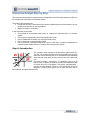
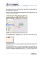
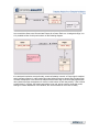
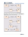
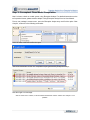
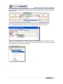
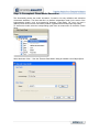
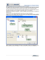
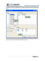
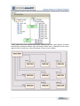
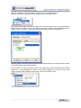
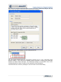
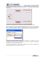
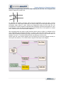
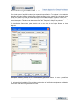
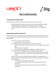
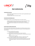
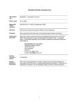
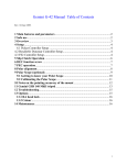
Step by Step
Table of Contents
Step 0: Introduction ................................................................................................. 3
Step 1: Conceptual Class Model Construction ........................................................ 4
Step 2: Conceptual Class Model Compilation ......................................................... 7
Step 3: Conceptual Class Model Execution .......................................................... 10
Paso 4: Conceptual Class Model Documentation ................................................. 27
Page 2 of 29
Visit us at www.enterpriseanalyst.net
Enterprise Analyst Step by Step
This document demonstrates a typical scenario of application of the Enterprise Analyst tool (EAn) in
the analysis and construction of a software system.
The goals of this document are:
• Provide the new EAn users with their first tutorial, explaining some common steps in its use,
as well as an idea of their own applications
• Mark the benefits of using EAn
In this document you will learn:
• The potential of a conceptual class model to capture the “business rules” of a software
system
• How to get to a syntactically correct conceptual class model
• How to validate the semantics of a conceptual class model
• How to document a conceptual class model
• How to generate a detailed design and a source code from a platform independent of
conceptual class model and how to continue fine-tuning the new system
Step 0: Introduction
The problem under analysis is the well-known game called TicTac-Toe. The system should let two human players start a game,
make their moves following the set of well-defined rules and finally
detect the end of the game, be it the victory of one of the players or
a tie.
The rules are simple – each player is ) assigned a sign (X or O)
that he uses to capture the fields of a board. The board has a total
of 9 fields, laid out in a 3x3 pattern. The players play alternately ,
until one of them captures 3 fields in a row (horizontal, vertical or
diagonal). If neither player gets to win a game and there are no
free fields left, the game ends with a tie.
Page 3 of 29
Visit us at www.enterpriseanalyst.net
Step 1: Conceptual Class Model Construction
The main source of information for this task is the problem specification from the previous section.
The goal is simple: to identify the critical problem concepts, their features and interrelations. To
learn the basics of the conceptual modeling, the chapter “UML Modeling in Enterprise Analyst” from
the User Manual can be of a great help.
For a conceptual class model construction in this example, the Enterprise Architect tool is used. The
first step is to create a new Enterprise Architect project. After this, select a class diagram (or create
a new one) and add it a new package:
The most adequate name for this package is “Tic Tac Toe”, showing the game name. After this
action, you should see the following situation on the UML diagram:
This package will be container for the rest of the element in our conceptual model. Double click on
this package will “open” it and create the first diagram automatically. Now we can proceed to a
conceptual model design.
The most obvious part of the Tic Tac Toe game is the game Board. The problem specification says
that a Board consists of a 9 Fields. This situation is clearly represented in the following class model
(note that the Field distribution is modeled as a UML note, that is, a comment. It is possible to make
a more formal modeling of a 3x3 Field distribution, but it is not necessary in this context):
Page 4 of 29
Visit us at www.enterpriseanalyst.net
Let us model the Game now. We need two Players for a Game. Each one is assigned a Sign: X or
O. A possible solution for this part is shown on the following diagram:
If we analyze this solution more profoundly, a serious limitation is noted – a Player sign is modeled
as his permanent feature. In other words, this model obliges Players to always play the same Sign!
A further consequence of this is that two Players with the same Sign could never play against each
other (without the Sign reassignment of course, but this leaves us with new problem – how to follow
a game history?). Anyway, the starting assumption is not real, and we need to modify the model,
looking for a better abstraction of the situation, the one that would be more close to reality.
Page 5 of 29
Visit us at www.enterpriseanalyst.net
The following model segment fixes the problem:
Now, the Sign is not a Player’s exclusive feature, but a feature of the relationship between the
Player and a Game. This makes those two concepts independent in the context of a Game.
To finish the initial Tic-Tac-Toe game modeling, the Moves should be incorporated. After adding this
concept and joining the parts in a whole, the final model is ready:
Page 6 of 29
Visit us at www.enterpriseanalyst.net
Step 2: Conceptual Class Model Compilation
Now it’s time to check our model syntax, using Enterprise Analyst. For detailed instructions on the
tool’s practical issues, please read the chapter “Using Enterprise Analyst” from its User Manual.
From a root package’s context menu, open the Enterprise Analyst entry and find the option “New
Compile”, as shown in the following screenshot:
Insert the class model and confirm the input:
Take a few moments to review the compilation report generated by Enterprise Analyst:
Note the single error message:
“The role of the class: <Game>, in the association between the classes: <Game> and <Player> is not
pecified.”
Page 7 of 29
Visit us at www.enterpriseanalyst.net
To fix this problem, we have to get back to our model in EA and update the mentioned association
properties. To do this, please open the association context menu and select the option “Association
Class Properties…”
From the properties dialog, open the “Source Rol” tab and set the Game rol to “game”:
Check out the class diagram to assure that the role has been correctly updated. After that,
recompile the class model from its context menu in the “EAn Control Panel”. The control panel has
been activated during the previous compilation.
Page 8 of 29
Visit us at www.enterpriseanalyst.net
Now, the compilation process finishes without errors and the class model elements are displayed in
the Control Panel:
Before continuing to the next step of this tutorial, take some time to investigate the properties of the
elements of the compiled model using Enterprise Analyst’s Control Panel.
Page 9 of 29
Visit us at www.enterpriseanalyst.net
Step 3: Conceptual Class Model Execution
This functionality permits the model “simulation”, focused to its early validation and semantics
correctness assurance. The facts that this is a platform independent model (in the terms of the
implementation details, such as programming language: Visual Basic, C#, Java, etc) and a
relatively small amount of time was used to produce it, guarantees the analysis process quality.
To execute the model, select the corresponding option from its context menu in the EAn’s Control
Panel:
Select the button “New…” from the “Execute Class Model” dialog to establish a new Object Space.
Page 10 of 29
Visit us at www.enterpriseanalyst.net
The Object Space provides a class model execution environment, acting like the container for the
objects and links created during the execution. Its main property is the package which will store the
object diagrams generated for you by the Enterprise Analyst. Insert the needed information to start
the execution (“TTT Simulation” for the object space name, “Objects” for the root package and a
“Game board” for the initial diagram).
After configuring the object space, the “Execute” button on the initial dialog is enabled. Select this
button to start the execution.
The Control Panel now permits the action execution:
Page 11 of 29
Visit us at www.enterpriseanalyst.net
To begin a Tic Tac Toe game, the first thing we need is a Game Board. The class model contains a
Board class for this purpose. Instantiate a new Board using the context menu of this class in the
Control Panel:
Just upon executing this action, the tool activates the Actions Dialog, which means that this object
cannot be created correctly without some additional actions. This dialog implements a
comprehensive inconsistency diagnostics and resolution tool for the model execution. Its goal is to
helpa modeler to execute all the needed actions, to “fix” the inconsistencies and leave the system in
a consistent state. Difficulties in the process of inconsistencies correction could discover class
model defects and assist a modeler to improve it.
Difficulties in consistent class model execution
reflect the difficulties in the consistent execution of the system after its implementation!
Enterprise Analyst permits to prevent the running system problems, that is, discover and fix the
analysis errors early in the development process.
Let us analyze just produced new Board instance inconsistency, using EAn.
Page 12 of 29
Visit us at www.enterpriseanalyst.net
Actions Dialog discoveres a lot of interesting information for a modeler.
The upper left part enlists the executed action(s). Its color indicates the action state in the terms of
its possibility to be actualy executed (red – the action’s execution cannot be finnalized because one
or more of the object affected by it is inconsistent. Green means it is ok to execute the action).
The upper right section of the dialog shows the objects affected by the individual actions. Its color
indicates its consistency (red – the object is inconsistent, green – it is consistent).
Selecting a “red” object, the “Diagnose…” button is enabled to show you the way to inconsistency
diagnostics tool.
The bottom part of this dialog displayes the action’s input and output “parameters”.
Getting back to our example, the Actions Dialog tells us that the executed action is “Object
Creation” of the Board class instance. However, the red color indicates that an inconsistency is
produced while trying to finish the action execution:
After a review of the information delivered by this dialog, select the inconsistent object
(Board1:Board) and press the “Diagnose…” button to see the EAn’s inconsistence diagnostics.
Page 13 of 29
Visit us at www.enterpriseanalyst.net
The Inconsistency diagnostics tool informs an inconsistence produced during the intent to create a
Board class instance. Its description clearly states that it is due to the association with the Field
class and the need to link the new object (Board1) with 9 Field class instances.
The inconsistence is perfectly reasonable and expected, since the Tic Tac Toe Board contains
excactly 9 Fields.
Let us see the possible inconsistence solutions, offered by Enterprise Analyst:
In this case we should choose to create the missing link and complete the game Board
construction. The next step is to actually employ the solution of our choice:
Page 14 of 29
Visit us at www.enterpriseanalyst.net
The chosen solution is to establish the missing links between the inconsistent object (Board1) and 9
instances of the Field class. However, those instances don’t exist in this moment (remember that
we have only created a single Board object), so we first need to create nine Field objects (“Create
Object” button) and then link them to the Board1 (enable the corresponding checkboxes).
Note that EAn won’t permit you to create more object than needed to resolve the actual problem.
Finally, press the button “Resolve”.
Page 15 of 29
Visit us at www.enterpriseanalyst.net
Getting back to the Actions Dialog, the extended list of the actions will be displayed, fixing the initial
inconsistence. There are 18 additional actions that were executed. Nine of them correspond to a
creation of the 9 Field instances and other 9 to a creation of the 9 links of each Field with the game
Board.
When the “Commit” button is pressed, the pending actions will be permanently executed in our
Object Space and the Game Board will be completely constructed!
Page 16 of 29
Visit us at www.enterpriseanalyst.net
The following screenshot shows the updated Control Panel display, including all the created objects
and links:
A More natural view of the updated object space certainly is the UML object diagram, generated
automatically by Enterprise Analyst. Open the diagram “Game board”, established as the current
diagram on the execution start. Layout the diagram to make it more readable:
Page 17 of 29
Visit us at www.enterpriseanalyst.net
The object names are generated automatically by Enterprise Analyst and they may be left like that.
However, sometimes is may be usefull to manually set more meaningfull values.
Select the “Attributes” menu item from the context menu of the object Field2:
Assuming that this object represents the upper left Field of the Board, we set its correct attribute
values (including the object name). The attribute “horizontal” indicates the horizontal position of the
Fileld (1 – left, 2 – middle, 3 – right), while the attribute “vertical” sets its vertical position:
After the update is confirmed, EAn will make the modifications effective and they will become visible
in the Object Space and the object diagram.
The next step in our game simulation may be the construction of the Players data base. Before
doing this, it is recommendable to switch to a new object diagram, due to the new view it will
provide. From the Object Space’s context menu, select the “Properties” item:
Page 18 of 29
Visit us at www.enterpriseanalyst.net
Press the button “New…” and set the new diagram name to “Players”. Using different object
diagrams for different object space views, a better clarity of the execution is achieved.
Once this new current diagram is established, the exercise may continue.
Applying the same instantiation procedure, just demonstrated with the Board class, create a Player
instance. Note that this time the object construction is finished without the Actions Dialog activation.
This is due to the fact the Player class does not require any mandatory links.
Set the new Player name to Peter. Create two more Players: Rene and Vera.
Take a look to the object diagram “Players”:
Our object space now has a full game Board and a small Players data base.
Page 19 of 29
Visit us at www.enterpriseanalyst.net
Enterprise Analyst permits customization of the execution process. Open, from the Enterprise
Architect mail menu, the following option: Add-ins Æ Enterprise Analyst Æ Execution Æ Options…
Modify, from the execution options dialog, the color of the links and edges of the association class
instance, as shown.
Now, we are ready to start a new Game! Before proceeding, let us once more switch to a new
current object diagram: “The game Peter vs Vera”.
Create, from the Control Panel, a new instance of the Game class. The Actions Dialog will be
displayed again, indicating failed intent to directly create the object.
Repeat the same diagnostics and resolution procedure shown before: select the inconsistent object
and press the “Diagnose…” button. After the Game object inconsistency analysis, we get to the
proposed solution – link it to two Player objects. Select the “Create Missing Link(s)” option and
press the “Resolve…” button.
Page 20 of 29
Visit us at www.enterpriseanalyst.net
Now, there is no need to create new objects, as we have already created three Players. We only
need to select two Players. Select Peter and Vera and press “Resolve”
Before leaving the Actions Dialog, note the pending actions list:
Two new actions created during the inconsistency resolution are of a type “Association Class
Instance Creation”. This is due to the modeling solution employed in resolving the relationship
between the classes Game and Player. This relationship actually is an association class, so the
corresponding action creates an instance of the association class Participation.
Commit the actions to continue, pressing the “Commit” button on the Actions Dialog.
Page 21 of 29
Visit us at www.enterpriseanalyst.net
Review the diagram “The game Peter vs Vera”. To complete the diagram, drag the objects Peter
and Vera from the Enterprise Architect’s Project View to it. The existing links are drawn
automatically:
The color of the new objects and its links indicates the instance of the association class.
Before making the first move, let us establish the Player’s Signs: Peter may play “O” and Vera may
take “X”. Note that this attribute belongs to a Participation class, due to the reasons explained
during the conceptual modeling. So, set the Participation15’s sign to “O” and the other one to “X”.
Enterprise Analyst offers additional assistance for the modification of the attributes of the type
enumeration: a selection list with the legal values only. This is a measure to prevent the
inconsistencies of the type “Inconsistent Attribute”.
After making the game Board, creating a Game between Peter and Vera and assigning the
corresponding game Signs, let us make the first move!
Page 22 of 29
Visit us at www.enterpriseanalyst.net
According to the game Signs, Vera should begin capturing the first Field. Let us suppose Vera
wishes to capture the central Field:
To represent this situation, the Move class should be instantiated in the first place. Just like
expected from our class model relationship, the Actions Dialog is activated again showing a new
inconsistent object (Move17). Upon entering the Diagnostics dialog, this time there are two
inconsistencies: the Move should be linked with both Participation (select the Participation16, since
it corresponds to Vera) and with the Field instance (select Field6, since it corresponds to a central
Field – check this out on the “Game Board” diagram”).
After committing those new actions, modify the Move object’s name to a Move1, to indicate the first
move. Additionally, set its attribute “sequence” to a value 1, due to the same reason. Here, you can
practice the inconsistence resolution by trying to set this attribute’s value to a non-number value, for
example “First move”. The Actions Dialog will show up, asking you to fix this error.
Review again the current object diagram (the new object’s color has been changed manually to
mark-up the new situation). You will also need to drag the Field6 object to the diagram.
Page 23 of 29
Visit us at www.enterpriseanalyst.net
The Control Panel offers an alternative view of the created objects and their corresponding links.
Check out the object Move1 and its links:
It’s a perfect moment to take an execution “photo”, that is to “memorize” this key situation of the
game. It would be very useful to have it well documented. To take an execution “photo”, select the
following option:
Now, it’s Peter’s turn. He wants to take the first Field, as shown:
To make this effective, another instance of the class Move must be made and linked with the
corresponding Field and Participation objects, etc.
After the first two execution steps, let’s stop the
execution and generate a sequence diagram
showing the actions executed by now:
Page 24 of 29
Visit us at www.enterpriseanalyst.net
The generated diagram should be similar to the following one:
After the execution session interruption, the logical execution thread was not broken; it can be
continued if the Object Space execution is started again.
The readers are encouraged to finish the exercise, until Vera’s final victory: The following figure
shows the final position:
The simulation was executed successfully. This means that the
conceptual model is correct and that it forms a solid base for
further development. The detail class model specification may
follow (Step 4 of this document), or maybe direct transformation to
the corresponding detail design or code. There are different
possible scenarios of following steps, but the most important is that
after exhaustive class model simulation, we have some indicators
that tell us that the analysis process has been done correctly.
In the case of more complex systems (models), it is most probable that some additional problems
will occur during the model execution. In those cases, the conceptual model should be reviewed,
fixed and improved, the model should be recompiled and the critical part of the execution should be
repeated. This process is highly iterative and leads to a model that supports all projected scenarios.
Besides the conceptual class model, the system use cases and/or test cases will typically form an
input to this kind of simulation. The preconditions, post conditions and some critical (or all!) use
case steps might be simulated using the proposed method and later documented using Enterprise
Analyst’s documentation feature. This way, the produced use case model will be a lot richer and
less ambiguous.
Page 25 of 29
Visit us at www.enterpriseanalyst.net
Note that the current version of this tool does not permit to capture detailed business rules. For
example, in the example shown here, there is no way to specify that two Players in the same Game
should have the different Signs, or that they should alternate in making Moves. Those details must
be added in the detailed system design and during implementation tasks. However, the validated
class model makes a solid base for further refinements. New releases of EAn will gradually
incorporate additional UML diagram compilers and simulators: state machines, sequence diagrams,
etc.
Page 26 of 29
Visit us at www.enterpriseanalyst.net
Paso 4: Conceptual Class Model Documentation
The visual aspect of any UML model is just a part od its specification. To complete it, it is needed to
describe the model element tipically using natural language. In the case of the conceptual class
model, this means to provide the textual descriptions for model packages, diagrams, classes, etc.
All of the UML elements in EA have a “Notes” property which is used to input the corresponding
textual description. This value can be accessed from the “Properties” dialog of any element:
To describe the Game class, please double click on the class in the Project Browser or class
diagram:
Enterprise Architect provides a RTF documentation generation feature. It uses a predefined
fdocument formats (templates) to generate model specifications.
To enhance this functionality, EAn provides a mechanism of specification completeness validation,
previous a usual document generation from EA.
Page 27 of 29
Visit us at www.enterpriseanalyst.net
Select the “Validate Documentation” option from the class model context menu in EAn Control
Panel:
This will open the Documentation Validation dialog.
Please select the object space to include it in the validation process and set the rigor level to
Medium. The rigor level establishes the set of elements which will be validated. The Low level
means that only high-level model elements (packages, diagrams) will be validated. The higher rigor
levels introduce class, association and attribute validation.
For this exercise, please select the Medium rigor level and press button “Validate”:
The following output is produced as a result – a list of model elements without proper specification
in the EA model:
Page 28 of 29
Visit us at www.enterpriseanalyst.net
The element list gives the information about the element type and location in the EA model. From
here you can easily detect not specified elements and complete their specifications.
Finnaly, you can generate the a model RTF document using one of EAn templates.
Page 29 of 29
Visit us at www.enterpriseanalyst.net