1
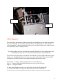
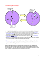
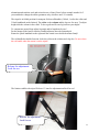
Gemini G-42 Manual Table of Contents
Rev.: 02.June 2009.
1 Main features and parameters.............................................................................2
2 Safe use ...................................................................................................................2
3 Overview.................................................................................................................3
4 Setup .......................................................................................................................4
4.1 Pulsar Controller Setup .....................................................................................4
4.2 Boxdörfer Dynostar Controller Setup..................................................................4
4.3 FS2 Controller Setup............................................................................................4
5 Slip Clutch Operation ...........................................................................................6
6 DEC function screw ..............................................................................................7
7 PEC operation........................................................................................................7
8 Polar alignment......................................................................................................8
9 Polar Scope (optional)...........................................................................................9
9.1 Getting to know your Polar Scope...............................................................10
9.2 Collimating the Polar Scope .........................................................................11
10 Notes on the pointing accuracy of the mount .................................................12
11 Gemini GHS 140 MkII tripod..........................................................................13
12 Troubleshooting.................................................................................................15
13 Options ...............................................................................................................15
13.1 RA head lock ................................................................................................16
13.2 Colour ...........................................................................................................16
14 Maintenance.......................................................................................................16
1
Gemini G-42 German Equatorial Telescope Mount
User’s manual
1 Main features and parameters
• Capacity: approximately 40 kg, depending on tube length.
• Weight: 22 kg (without cw. shaft)
• Power: 2A@12V or preferably 3A@24V (the values represent the recommended power supply
rating, not the actual consumption)
• Wide range of polar elevation adjustment (0 – 70 degree latitude)
• Adjustable, stick-free slip clutches
• Removable counterweight shaft (30.5mm counterweight bore required)
• max 7deg/sec slewing speed (with Pulsar and 24V only)
• 200 step, 1Nm, 1,32 Ohm-2A/phase stepper motors in both axes
• single cable connection from mount to driver
• PE of ±5 arcseconds (without P.E.C.) , cca 2” total with PEC (Pulsar only)
• Worm rotation period 200 sec
• Elevation screw pitch/turn: 2mm, cca 78’/turn
• Azimuth screw pitch/turn: 1,25mm, radius: 60mm, cca 72’/turn
• Mounting OTAs: (A) tube rings attached using the existing platform holes (304mm spacing),
(B) tube rings or other hardware attached to the optional universal adapter plate (you provide
fixing holes), (C) optional Losmandy (3”size) adapter fixed to the mount platform.
A precision drive system comprising ground steel worms, large 217 mm brass (RA) and anodised
aluminium (DEC) gear and microstepped stepper motors are standard. The worms are hardened
ground steel (18mm diameter), lapped in RA. Only high grade aluminium alloys, brass and
stainless steel are used for the machined parts. The RA and DEC heads are NC machined from an
oversized solid block. 2x2pc tapered roller bearings hold the axes.
2 Safe use
Make sure that the power source used is stable! Noisy power will cause malfunctions and may
eventually damage the Driver (Pulsar, FS2 or other). Switching Mode (e.g. laptop) power supplies
may (but not necessarily do) interfere with the Pulsar driver.
When rotating the telescope, watch the motor cable! It should never be stressed!
Keep the mount away from dust, sand and other kinds of dirt! Protect it from rain!
The mount should NEVER rest on the motors when stored or transported! Use your transport
case!
2
During transport the slip clutches should NOT be locked! The worm may suffer damage
otherwise.
3 Overview
OTA
platform
DEC
Function screw
DEC clutch
handle
RA clutch
handle
Polar finder mounting
Position.
Electronic
connector
Ra head lock
Counterweight
Shaft hole
PEC encoder
Azimuth
adjuster
Elevation
adjuster
3
4 Setup
1.
2.
3.
4.
5.
Polar align roughly,
Connect the mount to the Driver Unit,
Put the counterweight(s) on (slip clutches released),
Mount the telescope (dec motor towards the sky end),
Release the slip clutches and balance the telescope. (Remember that finders, guidescopes, large
focussers may introduce significant unbalanced weight, especially with Newtonians.),
6. Check and adjust polar alignment (see section 8 and 9),
7. Adjust the DEC function screw (see section 6),
8. Check Driver setup! (please read the Quickstart section of the Pulsar manual)
The mount is ready for use.
4.1 Pulsar Controller Setup
Please set the parameters in the Mount Parameters menu as follows. For a more complete guide
see the Pulsar Manual!
Total reduction RA/DEC 432
Main Gear
432
RA Rotation the correct value is to be found by trial (worm rotates clockwise when viewed from
motor end)
TrackCurr
800mA @12V or 950mA @24V
GoToCur
1200mA (max 1400mA)
Stop Curr
100-300mA (or same as tracking current for autoguiding)
MotFreq
255 for most quiet operation, cca 190 for smoothest tracking
These current settings give low noise and consumption (0,5A @ tracking, 0,9A@ GoTo) If you
need more torque, change the settings!
4.2 Boxdörfer Dynostar Controller Setup
Note: the Boxdörfer is not a supported driver and while it can drive the mount under most
circumstances no responsibility will be accepted for any malfunctioning.
Motor Current: Slow - Dec 0800 - Ra 0800 Fast - Dec 1000 - Ra 1000
Frequency: RA Slow 000.200548
Dec Slow 000.200548
Set Gearing: RA -005.529.600 (if the mount tracks incorrectly please change the sign)
Dec +005.529.600
4.3 FS2 Controller Setup
Note: the FS2 is not a supported driver and while it can drive the mount under most
circumstances no responsibility will be accepted for any malfunctioning.
4
Please set the parameters in the Mot1 and Mot2 menu as follows!
F*4
Curr1
0.7 A
Curr2
1.4 A (maximum)
Offset
Freq1
20 Hz
Accel
Freq2
0 Hz
Clear
Offset
0.02 A
Freq3
S/Rev
200
L/R
Gear
432
EncR
Wave
micro
EncD
0%
0.01
5 or best value
usually 0
40Hz
Left
none
none
Please set Misc/Teeth at 432!
Rate 5, which will be used for the GoTo function also, depends on the load and the power supply.
Try 500 and decrease if the drive fails! The maximum slewing speed depends also on supply
voltage. Acceleration (Accel) should be slow for heavy loads. For autoguiding select rate 1 which
should be set below 1 (siderial) to exclude any backlash.
To use any other controller that can drive bipolar stepper motors with at least 1A/phase you can
prepare your cable based on the DB15 connector (on the side of the DEC head of the mount)
pinout below.
RA
phase1 pins 4,5
DEC phase1 pins 1,2
phase2 pins 7,8
phase2 pins 9,10
5
The illustration below shows a typical physical setup of the mount, tripod and driver. Please
note the correct position of the declination motor (toward the sky end of the tube)!
5 Slip Clutch Operation
(RA. and DEC.)
Turn the handle right to lock, left to release!
Do NOT use excessive force on the locking handle! Lock it gently!
The slip clutch may be adjusted by lifting and turning the handle.
6
Please remember that the slip clutch is also a protection feature that prevents excessive force
from acting on the worm and gear! When the clutch is too tight and the telescope cannot slip
when accidentally bumped, the worm and gear will sufffer damage.
6 DEC function screw
To obtain the highest precision in autoguiding you can adjust the DEC function screw that acts
against the worm tensioning spring. To have no lost motion in DEC during guiding:
1) center your guidestar,
2) start with turning the screw out until it is definitely not acting against the spring. Now turn
the screw in about ¼ turn after you feel resistance (when the screw touches the worm
bearing) OR watch the guidestar on the computer display while turning the screw in and
stop after the star moves a few arcseconds. The second method is more sensitive.
3) Now the drive will respond instantly to changes in direction (it is necessary to slightly
unbalance the OTA in dec to obtain the best result).
Please note:
1 each time you change the position of the telescope the function screw has to be withdrawn
several turns and the above procedure repeated.
2 For visual observing and GoTo the screw should be withdrawn 2-3 turns.
Explanation: lost motion is the amount of rotation eaten up by small flextures in a mechanical
system. It is not backlash. Backlash is when there is play between two parts.
7 PEC operation
The PEC function is available with the Pulsar driver only. The PEC encoder is wired internally to
the electronic connector, there is no need to plug any cable in it.
To program PEC use a high magnification crosshair eyepiece (600x-800x) or a CCD autoguider
with about 1sec integration time. PEC can also be programmed using PemPro (CCDSoft). For
more details on programming see the Pulsar manual!
Once programmed, the PEC is kept accurate by the encoder, which uses a magnet glued to the RA
coupling.
7
Encoder
Magnet
8 Polar alignment
Elevation can be adjusted after slightly releasing the two handknobs (one on either side) locking
the polar or RA head. The elevation of the polar shaft can be adjusted by the rigt/left handed
screw mechanism. To adjust azimuth the central (on pier or tripod) locking screw (and the lateral
ones when fitted) must be slightly released
Tip: Adjust slightly above the pole and fine adjust after loading OTA and counterweight! Lock
the hand knobs firmly. Do not use tools other than your hands on the handknob!
There are three elevation ranges of the mount. The difference is in the length of the longer (right
hand) screw. Attention: the (lower) elevation screw safety mark indicates 8mm safety margin!
Turning it more out risks failure of the support mechanism and a serious injury.
Standard: 35 – 57 degrees latitude (shipped unless specified otherwise).
Low: 0 – 35 degrees latitude (the RA head must be reversed in the fork base)
High: 45 – 70 degrees latitude.
To make a drift alignment use the screw pitch values given in the first paragraph!
To use the mount in the Low range, the RA head must be reversed in the base!
The elevation scale will not work in this position unless the mount was ordered for low elevation originally.
8
9 Polar Scope (optional)
The G-42 can be equipped with an optional high precision, bright field Polar scope. This 12x30
finder uses a 20mm Plössl eyepiece and offers a smaller than usual field but provides better
precision than most other models. The large objective permits seeing faint stars that make the
alignment very accurate. The first time the mount is used the Polar scope should be collimated
with the Hour Axis using the 3 small thumbscrews (M4) in its adapter.
Off axis
plate
Collimation
thumbscrews
The 3 allen screws (1 spring loaded) hold the polar scope centered in the adapter,
the 3 thumbscrews are for collimation.
The 2 handknobs of the off axis plate should be turned a small amount at a time,
one ofter the other to avoid seizing of the positioning pin.
9
9.1 Getting to know your Polar Scope
To take advantage of the GoTo function of a transportable mount, Gemini have developed a high
precision Polar Scope (HP2). Compared to the previous model it has better eye relief and two
concentric circles in the center to make the collimation easier. When used with care this product
gives results comparable to a good drift alignment.
Counterlock
nut
Eyepiece locking
setscrew
Objective
lens
Illuminator
To focus the reticle remove the eyepiece but mark the position first with a piece of tape! You
must put it back exactly where it was, otherwise the starts (Polaris and the two companions) will
not match the circles on the reticle.
To focus the polar scope release the counterlock nut and rotate the objective lens!
10
9.2 Collimating the Polar Scope
field of wiev
Polaris
wanders on
this circle
Polaris
centered
0.
Sight Polaris through the Hour Axis bore! Attach the Polar Scope with the off-axis plate!
1. Center Polaris and focus the polar scope (by rotating the objective lens)! Use the elevation
and azimuth controls only! (see fig. above, left) Fix the objective lens (counternut). Rotate the
Hour Axis cca.180 degrees! Stop where Polaris goes farthest from the center!
2. Move Polaris halfway towards the center as shown (above, right)! Use only the Polar Scope
collimation thumbscrews now!
3. Repeat from 1 (except focusing) until Polaris stays in the center when the Hour axis is rotated
180 degrees! Until now you have been collimating the Polar Scope.
5 Rotate and adjust (in Az and Elev.) the Hour Axis until Polaris is in the large circle and the
two fainter stars around are in the smaller circles. Pay particular attention to the correct
position of the far-off-the pole star!
Note: you can go through steps 1-4 in daytime using a terrestrial object a few hundred meters
away. Do NOT remove or rotate the polar finder’s eyepiece after the alignment was done! You
will lose collimation. If the polar finder is stored carefully it will keep good collimation for a long
period. In this case you need to repeat step 5 only during the next setup.
11
10 Notes on the pointing accuracy of the mount
The pointing accuracy with a given setup is ensured by paying attention to the following:
1. Polar alignment The final alignment must be made with the telescope on the mount.
Otherwise mechanical effects will jeopardise accuracy. Polar finders without a collimation feature
will not give good results.
2. OTA optical axis (not mechanical) perpendicular to Declination axis
It is not always enough to use two identical tube rings. With reflecting and catadioptic telescopes
you should always make sure that the orthogonality is correct. After collimation of the optics it
will be necessary to repeat the test.
To check the orthogonality do the following:
1 Collimate your polar scope as described above!
2 Center Polaris in the fileld!
3 Align the telescope parallel with the Hour axis (should point to the Pole, or 90deg DEC)!
4 When you swing the tube in RA, Polaris should cross in the center of the field! If not, adjust the
tube on the platform! (put spacers under one end)
The DEC head of the G42 is milled from a solid block of aluminium on an NC machine and the
axes are perpendicular to each other within a few arcminutes. In practice most of the GoTo
pointing error comes from the optical axis misalignment. Inaccurate coordinate databases are also
to blame sometimes. Rotating a diagonal mirror after a GoTo for comfortable viewing can also
push the object off center.
Alternative method (without touching the polar alignment)
1 Center a bright star near the Meridian and preferably between 40-60 deg DEC!
2 Now slew to the North until you cross the Pole, then start to slew in RA towards the Meridian
(yes, about 12h in RA)!
3 when you are close to the target make a GoTo to the same star or slew manually to the
coordinates noted before so that the OTA is on the other side of the meridian! (Steps 2, 3 can be
done by activating a meridian flip with the Pulsar controller. Read the relevant section of the
Pulsar manual before proceeding!)
4 Ideally the star should be in the center of the field again (no star diagonals please!). If it is not,
correct half of the error in RA with spacers under the tube rings/adapter plate!
Note: it is important to have a good polar alignment when doing this test.
12
11 Gemini GHS 140 MkII tripod
Azimuth pin
Qlock
handknob
Collar
This tripod was designed using my experience with several traditional models (pier with
legs at the bottom, surveyor’s type tripod, SC field tripods, etc.). The most common problems of
these designs are: backlash at leg junctions, weak legs, small resistance to torsion, difficult setup,
interference with long OTAs. To overcome all these shortcomings I have developed the GHS
(Gemini High Stability) design which does not save on material where there is need for it (the
legs and the column have 5mm wall) but is still easily transportable (15.5kg). This design uses the
weight you put on it to stabilize itself due to a favorable geometry. It is constructed out of
13
aluminium and stainless steel and resists the test of time (I have left an example outside for 2
years and had to change the rubber grommets only, which are not UV resistant).
The tripod is in folded position for transport. Release all handles (2 black, 1 red) at the collar and
3 black handknobs at the limiters! The collar on the column and the legs are free now. To adjust
height slide the column in the collar! To do so grab and fix one leg between your thighs!
To compensate ground slope adjust leg angle and/or length one by one!
Put the mount on the head so that the azimuth adjusters meet the azimuth pin!
Rotate the Qlock handknob to the right until the central screw holds the mount firmly!
The red handle has double function: locks the collar on the column and a leg also. Do not release
the red handle when the mount is on the tripod!
Release for adjustment /
Lock for use
The limiters stabilize the tripod. Release 1/2 turn for adjustment and lock for use!
Release for adjustment /
Lock for use
14
The above photos illustrate the high (left) and low position of the GHS 140 tripod.
12 Troubleshooting
Drive does not start.
Incorrect polarity,∗ insufficient current, ∗ unstable/noisy power, ∗broken power cable, ∗
electronic transient, ∗ fuse blown .
Motors vibrate and do not turn the telescope.
Large unbalanced mass. Rebalance the telescope! ∗ Motor cables broken. Repair or replace!
Cable connector became loose at mount or driver end.
Motors run but do not turn the telescope.
Motor/worm coupling became loose. Tighten setscrews!
No PEC encoder signal arrives.
Magnet missing. Encoder broken.
There is backlash in declination. – The DEC function screw is turned in. Read section 6
carefully!
13 Options
15
13.1 RA head lock
The mounts ordered with the GHS tripod are shipped with the handknob shown in the overview
section. The mounts ordered for permanent setup are shipped with an M10 allen head screw. This
version allows more overhang after the meridian has been crossed.
13.2 Colour
Black mount with red handknobs and elevation adjuster.
Red mount with black handknobs and elevation adjuster.
Natural (silver) mount with black handknobs and elevation adjuster.
Blue mount with black handknobs and elevation adjuster.
The base, gear covers, worm blocks and platform are always black.
14 Maintenance
Anodised aluminium surfaces must be protected from the UV radiation by silicone or paraffin oil
a few times a year, or when dry. Use a soft cloth to apply the oil to the surface!
Apply silicone oil (aerosole) to the rubber grommets of the tripod regularly! Avoid prolonged
exposure to direct sunlight!
Acknowledgements
Special thanks to Dr. Dietmar Hager, Eiji Mori and Maarten Vanleenhove for their valuable
advice on the details of this manual.
16