1
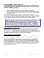
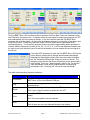
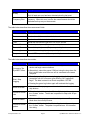
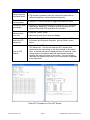
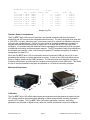
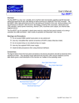
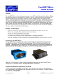
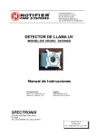
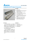
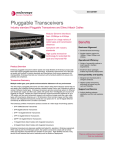
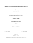
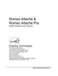
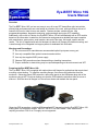
Eye-BERT Micro 10G Users Manual Overview: The Eye-BERT Micro 10G is a low cost, easy to use, all-in-one XFP based fiber optic test solution offering high performance bit error rate testing at a fraction of the cost while providing a rich set of features not found in other bit error rate testers. Features include: variable bit rate, user programmable patterns, diagnostic monitoring, and wavelength tuning (per XFP capability). Additionally, with a click of a button, the Eye-BERT Micro 10G will automatically test an XFP module based on the information it reads from the transceiver and generate a detailed test report complete with manufacturer, part number, serial number, date code, fiber type, link length, speed, and test results. The Unit is supplied with anti-skid bumpers for bench use, flanges for chassis mounting, and is small enough to be integrated into larger systems for dedicated link verification. Warnings and Precautions: Do not exceed XFP manufacturers recommended optical input power on any port Use only compatible fiber optical connectors and modules Use only the supplied 5VDC power supply Observe ESD precautions when disassembling or handling transceivers Proper ventilation or heat sinking may be required depending on the environment and XFP Preparing the Eye-BERT Micro 10G: The Eye-BERT Micro 10G is supplied with optional dove tail flanges for applications that require hard mounting or heat sinking. To install the mounting flanges, first remove the rubber feat from the enclosure. Observing proper ESD protection, remove the panel on the USB/power plug side of the enclosure using a #10 Torx driver making sure that the PCB inside the enclosure does not move or slide out. Slide the dove tail flanges in to the rails as shown and reattach the rear panel. Observing ESD precautions, install an MSA compliant XFP transceiver into the Eye-BERT Micro 10G making sure it is completely seated. See SFF INF-8077i for more details. Note: transceivers requiring more than 3.5W or a -5V supply are not supported. www.spectronixinc.com Page 1 Eye-BERT Micro 10G User’s Guide V 1.2 Installing the USB Driver and Powering the Unit On In order for Windows to recognize the Eye-BERT Micro 10G the USB driver must first be installed; after which the Eye-BERT Micro 10G appears as an additional COM port on the computer. Currently Windows XP, Vista, and 7 are supported. 1. Copy the file “cdc_NTXPV764.inf” from the supplied CD to the hard drive. 2. Connect power to the Eye-BERT Micro 10G using the supplied 5VDC adapter 3. Plug the Eye-BERT Micro 10G into a free USB port. When the hardware installation wizard asks for the driver location, browse to the “cdc_NTXPV764.inf” location on the hard drive and complete the installation. Note, on some operating systems such as Window 7, manual USB driver installation may be necessary. If the hardware installation wizard fails, go to “My Computer” > “Properties” > “Hardware” > “Device Manager”, and find the “Spectronix” or “SERIAL DEMO” entry under “Other Devices” and select “Update Driver”. At this point you will be able to browse to the location of the driver. Optional The Eye-BERT Micro 10G emulates a serial port via USB. When the device is plugged into a USB port, Window automatically assigns it a COM port number. This COM port is then used to communicate with the device. In order to determine what COM port Windows has assigned to the Eye-BERT Micro 10G, right click on “my computer” and select “properties”. In the properties window select the “hardware” tab. Click on “device manager” and expand the “Ports (COM & LPT)” item. Locate the “Spectronix, Inc.” entry and note the assigned COM number, (ie “COM3”). Install the Eye-BERT Micro 10G Application The Eye-BERT Micro 10G application requires Microsoft .NET Framework 4. This application will automatically be downloaded and installed over the internet if required during the installation process. If the installation fails or if a network connection is not available manually install the .NET Framework from the “MS NET Framework 4” directory on the CD then reinstall the application. Using the Supplied Eye-BERT 10G Application The Eye-BERT 10G Application is used for both the Eye-BERT 10G and the Eye-BERT Micro 10G and is able to determine which port Windows has assigned to the Eye-BERT and then automatically begin communicating with it. The Eye-BERT must be powered on and connected to a USB port prior to launching the Eye-BERT 10G Application. After starting the application, press the “Connection” button to automatically connect to the Eye-BERT, upon successful connection this button will turn green and the fields will begin to update. The user may also choose to select a specific COM port number from the drop down list; this is useful when there is more than one Eye-BERT connected to a computer. After communication is established the “Connection” indicator will turn green, the screen will be populated with the current measurements, and the XFP model and serial numbers will be displayed in the application header. www.spectronixinc.com Page 2 Eye-BERT Micro 10G User’s Guide V 1.2 The Eye-BERT Micro 10G has three modes of operation: Bit Error Rate Test mode, Repeater mode, and Frequency Generator mode. In repeater mode the input signal is simply looped through the XFP and retransmitted; this is the power up default. In bit error rate test mode the Eye-BERT Micro generates the specified pattern / bit rate while the detector attempts to synchronize to the pattern and count the bit errors. In frequency generator mode a 50/50% square wave is generated at the specified frequency. The frequency generator makes use of the programmable pattern generator to create 6 different frequencies at ratios of /64, /32, /16, /8, /4, /2. In this mode the pattern detector can be used to test at an effectively lower bit rate but the detector will over sample the received signal at the full rate. If a tunable XFP transceiver is used, the Eye-BERT Micro 10G has the unique feature of being able to change the transmitted wavelength. Selecting the Wavelength indicator from the main screen will display the “Set Transmitter Wavelength” dialog box shown to the left. The dialog box gives the user the option of specifying a new wavelength in units of either THz or nm. When entering a value in the THz box the “New Wavelength” value will be updated with the corresponding wavelength in nm. Pressing “OK” will set the new wavelength. The table below describes the status indicators: Indicator Description Connection Green indicates that the application is communicating with the EyeBERT Micro 10G on the indicated COM port. Log Green indicates logging is in process with the number of samples / seconds shown. Signal Sync Green: No loss of signal is reported by the XFP Red: A loss of signal condition is reported by the XFP Green: The BERT pattern detector is synchronized with the selected pattern Red: The correct pattern was not detected Error www.spectronixinc.com Green: No errors were detected during the last reading Red: At least one error was detected during the last reading Page 3 Eye-BERT Micro 10G User’s Guide V 1.2 Indicator History Frequency Error Description Green: No errors since the last reset Red: At least one error has been detected since the last reset Indicates that the device cannot generate the specified bit rate / frequency. When this error is active the measurements should be discarded as they may not be accurate. The table below describes the measurement fields: Measurement Description BER Bit Error Rate = number of bits errors / total bit count Errors Total number of bit errors since the last reset Count Total number of bits tested since the last reset Time Actual test time since the last rest = bit count / bit rate Receive Power Received optical power (dBm) as reported by the transceiver. Transmit Power Transmitted optical power (dBm) as reported by the transceiver. Wavelength Transmitted wavelength (nm) as reported by the transceiver Temperature Internal XFP temperature (°C) as reported by the transceiver. The table below describes the controls: Description Connect to The Eye-BERT Micro Start / Stop Logging Procedure • Press the “Connection” button to automatically search for the device and begin communications. • Alternatively, select the proper COM port using the drop down list; this is useful when more than one unit is connected to the same computer. • Press the gray “Log” button to start logging data. A dialog box will prompt the user for a file name; after clicking “OK” logging will begin. The data is stored in an Excel compatible .CSV file. • Pressing the green Log button again will terminate the logging. Select a bit rate • Select one of the preprogrammed standard bit rates from the tool strip buttons. Choose a custom rate • Enter the desired bit rate in the “Custom” bit rate text box and press the “Custom” button. The bit rate is specified in Gbps with 10 bps resolution. Select a Pattern • Select one of the preprogrammed standard patterns or Repeater Mode from the tool strip buttons. Choose a custom pattern • Enter any 64 bit pattern in the “Custom” pattern text box and press the “Custom” button. The pattern is specified as a 160 character Hex string. www.spectronixinc.com Page 4 Eye-BERT Micro 10G User’s Guide V 1.2 Description Generate a signal using Frequency Generator Mode Procedure • Select a standard or custom bit rate. • The frequency generator tools strip values will update with six different frequencies; select the desired frequency. Enable / Disable the transmitter • Select the Tx Power indicator to toggle the transmitter output Change the laser wavelength • Select the Tx Wavelength indicator to display the “Set Transmitter Wavelength” dialog box. Entering a value in the dialog box will have no effect if the XFP transceiver is not tunable. Reset the error history and bit error rate • Press the “History” button Get information about the XFP transceiver • Press the “Read XFP” button to decode and display the “XFP Information and Diagnostic Registers” pop-up window, shown below. Test an XFP Module • Press the “Test XFP” button to perform automated testing on an XFP transceiver. The test first reads the XFP registers then performs bit error rate testing on the device based on the values read. A detailed test report is displayed within 20 seconds. Note: testing requires a loopback cable and attenuator be attached between the input and output of the module. Failure to properly attenuate the loopback may result in poor performance or damage to the transceiver. • Alternatively press the bit error rate display “Read XFP” Registers and “Test XFP” Results www.spectronixinc.com Page 5 Eye-BERT Micro 10G User’s Guide V 1.2 Eye-BERT Micro 10G Log file 5/4/2011 Time Rate Pattern Temp(C) Rx Power (dBm) Count Errors BER 10:15:33 AM 1.07E+10 PRBS31 30 -9.3 4.4E+11 2 4.54E-12 10:15:34 AM 1.07E+10 PRBS31 30 -9.3 4.48E+11 2 4.47E-12 10:15:35 AM 1.07E+10 PRBS31 30 -9.4 4.56E+11 2 4.38E-12 10:15:36 AM 1.07E+10 PRBS31 30 -9.4 4.68E+11 2 4.27E-12 10:15:37 AM 1.07E+10 PRBS31 30 -9.3 4.78E+11 2 4.19E-12 10:15:38 AM 1.07E+10 PRBS31 30 -9.4 4.89E+11 2 4.09E-12 10:15:39 AM 1.07E+10 PRBS31 30 -9.4 4.97E+11 2 4.02E-12 Sample Log File Thermal / Power Considerations The Eye-BERT Micro 10G enclosure provides a low thermal resistance path from the internal electronics and XFP module to the extruded aluminum housing. The unit is designed to be used with a 3.5W XFP in an open “laboratory type” environment (such as on a bench) or attached to a thermal sink using the included flanges. If the unit is to be utilized at elevated temperatures, mounted in a stagnant environment where heat build up might occur, or is used with an XFP with high power dissipation, it is recommended that additional thermal management be employed such as using fans or additional heat sinking and thermal gasket material. The XFP temperature may be monitored from the software user interface. Note, most commercial grade XFP modules are rated for an ambient temperature of at least 70°C. When the Eye-BERT Micro 10G is connected to an active (powered) USB port, the unit is on and generating heat whether or not the application is running. In order to turn off the unit either remove power or unplug / deactivate the USB connection. The unit will power down when the connected computer powers down, providing that the computer removes power from the USB cable. This allows the unit to remain connected to a system and powered on / off with the controlling computer. Mechanical Dimensions 3.50” 1.20” 1.43” 0.220” Slot width 3.20” 3.66” (mounting centers) 3.80” (overall) 2.75” Calibration The Eye-BERT Micro 10G utilizes optical power and temperature measurements as reported by the XFP module therefore the accuracy and calibration of these measurements is entirely dependent upon the XFP module. The Eye-BERT Micro 10G pattern generation, detection, and timing parameters are all based on digital circuitry within the module and therefore require no calibration. www.spectronixinc.com Page 6 Eye-BERT Micro 10G User’s Guide V 1.2 Letter of Volatility The Eye-BERT Micro 10G contains both volatile and non volatile memory. Only the Eye-BERT Micro 10G firmware application is stored in non volatile memory and program variables and settings are stored in volatile RAM which is cleared upon power down. The user has no means of altering the non volatile memory without opening up the unit and reprogramming the device using a special programming adapter. www.spectronixinc.com Page 7 Eye-BERT Micro 10G User’s Guide V 1.2