1
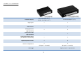
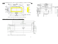
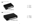
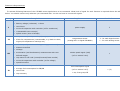
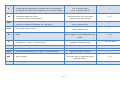
Universal Trip Computer (UTCOMP-3 & UTCOMP-PRO)
User & assembly manual.
Last update: 2015-09-11
www.REVELTRONICS.com
Please read this manual carefully before device using.
Contents
1.
Technical data and requirements .......................................................... - 5 -
2.
Assembly manual ................................................................................ - 11 -
2.1. General remarks ............................................................................................................................................................................ - 11 2.2. Pinout........................................................................................................................................................................................... - 12 2.3. Pinout description .......................................................................................................................................................................... - 13 2.4. Wiring diagram .............................................................................................................................................................................. - 14 2.4.1. POWER SUPPLY ........................................................................................................................................................................ - 15 2.4.2. KEYBOARD .............................................................................................................................................................................. - 15 2.4.3. BUZZER .................................................................................................................................................................................. - 16 2.4.4. TEMPERATURE SENSORS DS18B20............................................................................................................................................. - 16 2.4.5. FUEL CONSUMPTION SIGNAL ..................................................................................................................................................... - 17 2.4.6. VSS – Vehicle Speed Signal ....................................................................................................................................................... - 19 2.4.7. HEADLIGHTS or FAN COOLER .................................................................................................................................................... - 20 2.4.8. ANALOG SENSORS - Adc and AdcVcc inputs ................................................................................................................................ - 20 2.4.9. LPG System ............................................................................................................................................................................. - 20 2.5. Graphic display: LCD or OLED.......................................................................................................................................................... - 21 2.6. Additional instructions for assembly ................................................................................................................................................. - 22 -2-
3. User manual ............................................................................................. - 23 3.1. Quick start .................................................................................................................................................................................... - 23 3.2. First start in the vehicle .................................................................................................................................................................. - 25 3.3. Calibration of speed and fuel consumption ........................................................................................................................................ - 26 3.3.1. Initial calibration ...................................................................................................................................................................... - 26 3.3.2. Accurate calibration - achieving accuracy better than 1% .............................................................................................................. - 28 3.4. Menu navigation ............................................................................................................................................................................ - 30 3.5. Overview of screens and related functions......................................................................................................................................... - 30 3.5.1. Screen 1 - Temperatures ........................................................................................................................................................... - 31 3.5.2. Screen 2 - Tacho ...................................................................................................................................................................... - 31 3.5.3. Screen 3 – TRIP (daily counter) ................................................................................................................................................. - 33 3.5.4. Screen 4 – Trip-meter for off-road .............................................................................................................................................. - 34 3.5.5. Screen 5 – Fuel tanks ............................................................................................................................................................... - 35 3.5.6. Screen 6 – Measurement of acceleration/deceleration ................................................................................................................... - 35 3.5.7. Screen 7 – Oscilloscope ............................................................................................................................................................. - 36 3.5.8. Screen 8 – Clock ...................................................................................................................................................................... - 37 3.5.9. Settings screens ....................................................................................................................................................................... - 37 3.6. Review of other functions ................................................................................................................................................................ - 38 3.6.1. Headlights reminder ................................................................................................................................................................. - 38 3.6.2. Inspection / Service .................................................................................................................................................................. - 38 3.6.3. Travel costs ............................................................................................................................................................................. - 39 -
-3-
3.6.4. Black ice alert .......................................................................................................................................................................... - 39 3.6.5. Alerts ...................................................................................................................................................................................... - 39 3.6.6. Trip summary .......................................................................................................................................................................... - 40 3.6.7. Units change ............................................................................................................................................................................ - 40 3.6.8. Battery voltage (Voltmeter) ....................................................................................................................................................... - 40 3.6.9. User defined screens................................................................................................................................................................. - 41 3.6.10. Adjusting brightness ............................................................................................................................................................... - 42 3.6.11. Adjusting contrast .................................................................................................................................................................. - 42 3.6.12. Data-Logger........................................................................................................................................................................... - 42 3.7. Settings device parameters ............................................................................................................................................................. - 43 3.7.1. Configuration parameters .......................................................................................................................................................... - 43 3.7.2. User preferences ...................................................................................................................................................................... - 44 3.7.3. Screen settings ........................................................................................................................................................................ - 44 3.7.4. Advanced settings .................................................................................................................................................................... - 44 4.
Attachments........................................................................................ - 45 -
4.1. APPENDIX A – Analog temperature sensors (NTC) calibration .............................................................................................................. - 45 4.2. APPENDIX B - Troubleshooting ........................................................................................................................................................ - 46 4.3. APPENDIX C - Frequently Asked Questions (FAQ) ............................................................................................................................... - 49 -
-4-
1. Technical data and requirements
Universal Trip Computer (UTCOMP) developed and manufactured by REVELTRONICS is an on-board computer designed for wide range of
vehicles. It takes information from main sensors then process data and sends to LCD or OLED screen with user friendly interface.
Technical parameters
•
power supply from 12V or 24V installation (safe range: +8… +32V DC),
•
power consumption in standby mode: 4-12mA@12V (typ. 8mA@12V),
•
power consumption in idle mode: 40-500mA@12V (depends on used display, brightness, connected sensors etc.),
•
operating temperature: -40C…+85C,
•
LCD operating temperature: -20C...+70C (recommended +10C...+40C),
•
OLED operating temperature: -40C...+85C,
•
digital temperature sensors measurement range: -55C...+125C, accuracy 0,5C, resolution 0,1C,
•
vehicle speed accuracy: +/- 1km/h or mph (calibration possible),
•
acceleration measurement accuracy: +/- 0,1s (for VSS constant < 0.2 [m/imp]),
•
fuel consumption accuracy: 1% for petrol engines, 2% for petrol + gas engines, 1-3% for diesel engines (calibration possible),
•
sampling time of real-time fuel consumption: average from 1s, 2s or 3s,
•
sampling frequency from analog sensors: 50Hz,
•
analog sensors measurement accuracy: +/- 0,1 [V],
•
voltmeter accuracy: +/- 2% range +/- 0,1V (calibration possible),
•
supported units: km, km/h, l/100km, l/h, km/l, mil, mph, mpg, Celsius, Farentheit, bar, psi, volt,
•
communication with PC via USB 2.0 (HID).
-5-
UTCOMP-3 vs. UTCOMP-PRO
Compatible displays:
LCD 122x32pix (2,5")
OLED 122x32pix (2,3")
OLED 256x64pix (3,2")
Digital inputs:
4
5
Digital outputs:
-
1
2
4
-
1
1
2
2
4
4
6
(2 digital + 2 analog)
(4 digital + 2 analog)
-
logging up to 10 parameters
Analog inputs 0-5V:
(high impedance)
Analog inputs 0-30V:
(high impedance)
Analog inputs with 5V pull-up:
(for resistance or NTC sensors)
Digital temperature sensors:
Total no of temperatures:
Data-Logger
-6-
Display dimensions [mm]: LCD 2,5" (left) and OLED 2,3" (right) for UTCOMP-3*:
*NOTE: on the bottom side is soldered socket for IDC40 tape.
Display dimensions [mm]: OLED 3,2" for UTCOMP-PRO**:
**NOTE: on the bottom side is soldered socket for IDC16 tape.
-7-
Module dimensions: UTCOMP-3:
Width:
90 mm
Depth:
65 mm
Height:
20 mm
Width:
120 mm
Depth:
83 mm
Height:
29 mm
Module dimensions: UTCOMP-PRO:
-8-
Features & Requirements:
To activate following features of the UTCOMP some signals have to be connected. What kind of signal for each function is required shows the table
below. You should connect only what are you interested with. You do not have to connect all signals.
Group
I
II
Example features
•
date and time
•
battery voltage (voltmeter) + alerts
•
travel time
•
service & inspection with reminder (x2 for motohours)
•
customizable user screen(s)
•
splash screen (text or bitmap)
•
temperatures (inside, outside, oil, engine, user-1, user-2)
•
alerts for temperatures (customizable, e.g. black ice alert,
engine/oil temperature warnings etc.)
III
IV
•
vehicle speed (real-time velocity, average, maximum)
•
distance travelled
•
mileage
•
acceleration (and deceleration) measurement with user
trip meter for off-road (normal/reverse/freeze modes)
•
service & inspections with reminder (x4 for milage)
•
speed limit alert
•
current fuel consumption for PB/ON
•
average fuel consumption for PB/ON
•
travel cost
•
trip summary
No of wires
power supply
3
temperature sensor
3 - for each digital sensor
(analog NTC or digital DS18B20)
1 - for each analog sensor
vehicle speed signal (VSS)
defined ranges
•
Requirements
(ref. to section 2.4.6)
1
fuel consumption signal
(ref. to section 2.4.5)
+ req. from group III
-9-
1 (2)
V
•
full support for vehicles with LPG system
•
independent measurements of distance & fuel consumption
signal from LPG electrovalve or injector
(ref. to section 2.4.9)
for PB and LPG (with auto-recognition of current fuel supply)
VI
VII
VIII
1
+ req. of groups III & IV
•
fuel level in fuel tank(s)
•
estimated distance to refuel
•
low fuel level alert (configurable)
(measurement from sensor)
•
headlights reminder (for the vehicle in traffic)
signal from headlights relay
•
dimmer (2 modes of brightness e.g. day/night)
•
fan cooler status (on/off)
req. of groups III, IV, (V) (differential
measurement) or fuel level signal
(ref. to section 2.4.7)
signal from fan cooler relay
(ref. to section 2.4.7)
0 (1)
1
1
from fuel consumption signal (some
IX
•
RPM
petrol engines) or signal from RPM hall
0 (1)
sensor
•
boost/turbo pressure + alerts + real-time chart
•
oil pressure + alerts + real-time chart
XI
•
lean/reach real-time chart from O2 sensor
XII
•
air fuel ratio (AFR) + alerts + real-time chart
XIII
•
exhaust temperature (EGT) + alerts + real-time chart
X
pressure sensor
(voltage or resistance type)
1 - for each sensor
signal from o2 lambda sensor
1
signal from wideband o2 controller
1
signal from EGT controller
1
req. of groups III & IX (measurement
XIV
•
gear indicator
from gear ratio) or signal from gear
0 (1)
position sensor
XV
•
data logger
function available only in UTCOMP-PRO
- 10 -
-
2. Assembly manual
IMPORTANT: Read the following instruction before installing UTCOMP. The warranty does not include damage caused by improper installation.
2.1. General remarks
UTCOMP-3 has a 24-pin MOLEX connector. UTCOMP-PRO has a 24-pin and 12-pin MOLEX connectors. The kit comes with a plug with cables to solder.
Pay special attention to the numbered pins. All cables used to be install must be the dedicated automotive (FLRY), recommended 0.35 – 0.5 mm2
cross-section with insulation resistant to mechanical damage (abrasions, cracks etc.). All connections must be effectively soldered and hotair shrink
insulation (unconnected wires too). First you need to solder all the needed wires to the pins, and only then connect the plug to the socket device.
Before the first connecting plug to the device, make sure that the appropriate signals have been soldered to the corresponding pins of
the plug. Connect the LCD/OLED display before connecting the 24-pin connector.
- 11 -
2.2. Pinout
Connectors pinout (module side):
Plugs pinout (wire side):
Connector "A" (UTCOMP and UTCOMP-PRO)
Connector "B" (UTCOMP-PRO)
PIN
LABEL
PIN
LABEL
PIN
LABEL
PIN
LABEL
A1
SW_GND
A13
-
B1
DigInUser (RPM)
B7
DigOutUser
A2
-
A14
SW_3
B2
Adc3 (0-5V)
B8
AdcVcc2 (0-5V, +5V PULL-UP)
A3
SW_2
A15
SW_1
B3
Adc4 (0-5V)
B9
Adc5 (0-30V)
A4
DS18B20-A_GND
A16
DS18B20-B_GND
B4
DS18B20-D_GND
B10
DS18B20-C_GND
A5
DS18B20-A_DQ (signal)
A17
DS18B20-B_DQ (signal)
B5
DS18B20-D_DQ (signal)
B11
DS18B20-C_DQ (signal)
A6
DS18B20-A_VCC (+5V OUT)
A18
DS18B20-B_VCC (+5V OUT)
B6
DS18B20-D_VCC (+5V OUT)
B12
DS18B20-C_VCC (+5V OUT)
A7
BUZZER_GND
A19
BUZZER_VCC (+5V OUT)
A8
Adc1 (0-5V)
A20
AdcVcc1 (0-5V, +5V PULL-UP)
A9
Adc2 (0-5V)
A21
DigInHC - HEADLIGHTS/COOLER
A10
DigInFc1 - FUEL CONS. SIGNAL
A22
VEHICLE SPEED SIGNAL (VSS)
A11
DigInFc2 - LPG/RPM
A23
+12/+24V IGNITION
A12
GND (vehicle ground)
A24
+12/+24V BATTERY
- 12 -
2.3. Pinout description
GROUP
DESCRIPTION
Battery A12 (-), A24 (+)
power supply for the device, safe range is +8V...+32V DC (0,6A fuse is built-in in UTCOMP module)
Ignition (A23)
positive voltage from ignition switch (0V - low state, 5V and more - high state) - wake up UTCOMP from sleep mode
SW...
output for the three-button keypad (monostable switches, powered +5V from UTCOMP, press button shorts to GND)
DS18B20...
output for digital temperature sensors (3 wires for each sensor) – keep out for power supply! – reverse connection VCC/GND can damage sensor
Buzzer...
pinout for buzzer (VCC = +5V OUT)
Adc...
input voltage signal from analog sensors, e.g. lambda o2 sensor, wideband o2 controller, pressure sensors, temperature sensor (NTC), TPS etc.
AdcVcc...
input for resistance sensors (pull-up to +5V from UTCOMP), e.g. temperature sensor (NTC), resistance pressure sensors etc.
DigInFc1 (A10)
input injector control signal (PWM 0V… +12V, or 0V….+5V) or fuel consumption signal (PWM/FREQ)
DigInFc2 (A11)
input signal from the LPG system (e.g. status LED indicator or electrovalve: 0V (OFF) – petrol +3…12V (ON) – lpg) or RPM signal from hall sensor
DigInHC (A21)
input signal from headlights or fan cooler relay: +12V (ON), 0V (OFF)
DigInUser (B1)
user input signal, e.g. RPM signal from hall sensor
DigOutUser (B7)
user output signal, e.g. relay 5V@100mA control
VSS (A22)
input signal from vehicle speed sensor - VSS (0V – low state, 5V and more – high state)
- 13 -
2.4. Wiring diagram
- 14 -
2.4.1. POWER SUPPLY
Pin A24 connect to +12V/+24V (BAT), and pin A23 to +12V/+24V ignition switch (voltage occurs when the ignition key is turned on). Pin A12
connect to the vehicle ground (GND). The power line is already protected with 0,63A fuse built-in UTCOMP, so additional fuse is not necessary.
2.4.2. KEYBOARD
Kit includes three-button keyboard. You should solder 4 wires to keyboard from UTCOMP: A1, A15, A3, A14.
- 15 -
2.4.3. BUZZER
2.4.4. TEMPERATURE SENSORS DS18B20
Kit includes two (UTCOMP-3) or four (UTCOMP-PRO) digital temperature sensors DS18B20. Each sensor has 3 terminals: GND (GROUND), DQ
(SIGNAL) AND VCC (POWER SUPPLY).
Pay special attention to the outputs – it is easy for mistake changing side wires and burning the sensor (if mistake is done then nothing may be
displayed on the screen). Isolation wire leads are recommended using hotair shrink insulation1. In UTCOMP-3 application you can associate sensors with
1
please take a look at short video tutorial: https://www.youtube.com/watch?v=R8Z66qtYowA
- 16 -
temperatures, so connection order does not matter. For inside temperature sensor we recommend to place it in the place of free heating air, sun rays
etc. For outside temperature sensor we recommend to place it ahead cooler in a low place or at the bottom of side mirror. The correct placement of
sensors is a key influence on subsequent accuracy of the actual temperature.
2.4.5. FUEL CONSUMPTION SIGNAL
Injector control signal (PWM) or dedicated fuel consumption signal (PWM/FREQ) connect to pin A10. There are few places when you should looking
for these signals - it depends on engine type:
Petrol engines:
•
option 1 : directly on the injector connector – two pins should be in there (or more in case of mono injection). When the engine is ON, one pin is
+12V constant signal, the other one is pulse signal 12V…0V (PWM injectors GND controlled). Pulse signal should be connected to pin A10 of
UTCOMP (sample waveform is shown below),
•
option 2: to the appropriate pin in the ECU connector (injector control) - pinout for ecu connector can be found in electrical documentation
(wiring diagrams) of the vehicle
Petrol engines with LPG:
•
option 1: to the appropriate pin in the ECU connector (petrol injector control) - pinout for ecu connector can be found in electrical documentation
(wiring diagrams) of the vehicle. You should not connect directly to injector connector because there is no signal when engine is running on lpg.
- 17 -
Diesel engines:
In diesel engines you should looking for dedicated fuel consumption signal (PWM or FREQ). Usually it is called as “Trip Computer – TC”, “fuel
consumption signal” or less specific: “instrument panel signal”, “multifunction display” , “mfa” etc. Remember – some diesel engines do not have such
signal. Feel free to contact us if you have problems with locating such signal – we will try to help.
•
option 1: to the appropriate pin in the ECU connector,
•
option 2: the signal may be often located on the injection pump connector,
•
option 3: in most cases appropriate signal can be found in instrument panel connector (e.g. in TDI, HDI, DTI, TDDI etc. ) - note: CAN signal is
not supported!
•
option 4: in cars with PD injectors (e.g. 1.9TDI PD) signal can be taken directly from appropriate pin in the ECU connector (PD injector control)
but most these engines have dedicated fuel consumption signal (fuel consumption measurement will be more accurate with dedicated signal)
Please note: In every case search for PWM (pulse width modulated) or FREQ (frequency pulses) signal (controlled by the GND or +12V). Sample
waveform is shown above. Pulse width (for PWM signal) or pulse quantity (for FREQ signal) should be proportional to the current consumption. In most
cases injector control signal will be PWM(-) controlled. Dedicated fuel consumption signal will be PWM(+) controlled (rarely FREQ) but this is no rule.
Later, you will need to set type of signal in UTCOMP settings.
In latest diesel vehicles with CAN system (generally since ‘05) there is not available dedicated fuel consumption signal. Most diesel engines from 1994
to 2004 (with electronic injection pump or common rail) have such signal.
There is also alternative method for common-rail engines without fuel consumption signal - there are two important requirements:
•
possibility to measure fuel injection timing (from injector2) – max 150V amplitude,
•
possibility to measure fuel pressure: signal from fuel pressure sensor (it's located on common-rail tube) connect to Adc1 or Adc2 inputs and set
input configuration as "fuel pressure sensor (diesel common-rail)"
2
piezoelectric injectors with 2-pin connector are compatible ; for electromagnetic 2-pin injectors you will need additional signal converter, e.g. CR-PWM
- 18 -
2.4.6. VSS – Vehicle Speed Signal
The pulse speed signal (VSS) connect to pin A22. There are few places when you should looking for speed signal:
•
option 1: some vehicles have a VSS signal in the ISO socket of the radio (function volume up with increasing velocity) – generally pin 1 in socket
A (called as SPD, GAL, VSS etc.)
•
option 2: in most cases speed signal can be located in instrument panel connector (marked usually as speed1, speed2, vehicle speed etc.) –
take a look in the vehicle's electrical system documentation for the signal connector from tachometer (pinout).
•
option 3: if vehicle is with electronic injection system , VSS signal can be found at the ECU connector (even for vehicles with tachometer "on
cable") – check ECU pinout (electrical system documentation) which pins to select,
•
option 4: connect straight to VSS sensor, which you can find in a gearbox body. The sensor can be two-pins (power and VSS signal) or threepins (additionally the GND wire is connected). Connect to the pin on which there is a pulsed signal (0..+12V) when the car is moving (usually
few pulses for one turn of the wheel),
•
option 5: if your car is equipped with ABS than required signal can be found in one of the ouputs of ABS control unit,
•
option 6: if your car definitely does not have VSS signal than you can install universal speed sensor (hall sensor + magnets) – described in other
manual (can be downloaded from our webpage)
Below is an example of a pulse signal from the VSS sensor (vehicle pushed)
In most latest cars, instead of speed sensor, there is signal sending from ABS control module or from instrument panel – signal will be the same as
this one at the picture above.
There is a small percentage of vehicles that have electronic fuel injection, and do not have the speed sensor. In this case, the sensor can be installed
yourself (in the gearbox - if the manufacturer predicted such possibility), or assembly the usual hall sensor (option 6).
- 19 -
2.4.7. HEADLIGHTS or FAN COOLER
In order to activate the signaling function of the radiator fan OR headlight reminder, appropriate signal (+12V when the fan/headlights is turned on,
0V when turned off) should be connected to pin A21. After assembling, appropriate option should be chosen in UTCOMP PC application (cooler state
info or headlight reminder).
2.4.8. ANALOG SENSORS - Adc and AdcVcc inputs
UTCOMP-3 supports 3 analog inputs (Adc1, Adc2, AdcVcc1), UTCOMP-PRO supports 7 analog inputs (Adc1, Adc2, Adc3, Adc4, Adc5, AdcVcc1,
AdcVcc2). Example of use: analog temperature sensors (NTC), boost pressure from MAP/MAF, oil pressure sensor, lambda o2 sensor, AFR readings
from wideband o2 controller, exhaust temperature from EGT controller, fuel level, gear indicator etc.
Adc1, Adc2, Adc3, Adc4 and Adc5 are high impedance, buffered inputs - you can connect voltage signals from any analog sensors assembled in the
vehicle. Adc1-Adc4 are 0-5V range. Adc5 input is 0-30V.
AdcVcc1 and AdcVcc2 inputs have built-in divider with pull-up to +5V, so you can connect to them any additional resistance sensors, e.g. NTC
temperature sensors, resistance pressure sensor, fuel level sensor etc. UTCOMP measures voltage drop directly at resistance sensor. Please note: you
should NOT connect any factory vehicle sensors to AdcVcc inputs! (factory sensors are already powered from vehicle installation - in this case
connect voltage signal to any of Adc1 - Adc5 inputs).
In UTCOMP application you can associate each sensor with appropriate analog input, so connection order does not matter. For all analog inputs you
can activate oscilloscope (real-time voltage drawing on chart) and set dedicated alerts (e.g. to low oil pressure, to high boost pressure, to high
engine/oil temperatures, AFR outside safe range, to high EGT etc.).
2.4.9. LPG System
There are two solutions for connecting LPG signal: (1) binary signal or (2) lpg injector control signal. In both cases appropriate signal should be
connected at pin A11. UTCOMP auto-recognize current fuel type (petrol/lpg) and do independent measurements (distance and fuel consumption) for
both modes.
- 20 -
1. LPG binary signal (recommended)
This type of signal inform UTCOMP about current fuel type (low state 0V - petrol, high state 3V and more - lpg). It can be signal from LED
indicator or from LPG electrovalve. This solution is recommended for most vehicles with 4th generation of LPG system.
2. LPG injector control signal
This solution is recommended only for vehicles with factory LPG system (single ECU for petrol and lpg). In this case at pin A10 is connected
petrol injector control signal and at pin A11 is connected lpg injector control signal. Only single injector should be controlled at the
moment. Working injector indicate UTCOMP about current fuel type. Both injectors should be controlled the same method (both PWM- or
both PWM-). Common ECU guarantee that signal at pin A10 will not appear when there is already signal at pin A11.
2.5. Graphic display: LCD or OLED
Kit includes a graphical display with a resolution of 122x32 pixels for UTCOMP-33
and 256x64 pixels for UTCOMP-PRO. The display must be
connected to the UTCOMP using a dedicated ribbon tape. The tape has a special key so that it cannot be wrong side connected. Standard tape length is
60cm for UTCOMP-3 and 100cm for UTCOMP-PRO. To properly run, the display should be connected before power is connected to the device.
Due to the huge variety of mounting preferences of users, the display is supplied without housing (there is possibility to buy enclosure too). Take
special care during installation. Do not use any glues or substances that can conduct electricity. If you use two-component epoxy adhesives avoid
electrical pads. Before connecting the display, wait until the glue completely dries (evaporate moisture). The display can be freely located in the car - it
all depends on the user imagination and dexterity. The most frequently used locations are around the center console/dashboard or in the instrument
panel. Display should be assembled in a visible place, as close as possible driver's eye level. Avoid selection of direct sun and very warm places. LCD
contrast and refresh rate is optimized for 10-40C temperature range. OLED is characterized with about 180deg. view, high contrast and refresh rate in
wide range of temperatures (-40C...+85C). You will find many examples of assembly on our webpage.
3
There are two version of UTCOMP-3: LCD and OLED
- 21 -
2.6. Additional instructions for assembly
The most important notes are given in Chapter 2.1. Notes of the LCD/OLED assembly are given in Chapter 2.4. Additional assembly guidelines are
listed below:
•
before connecting the signal to the device, make sure you connect the appropriate cable (check the signal with a multimeter or
oscilloscope) – warranty does not cover damage caused by unprofessional and improper installation,
•
while connecting / disconnecting the plug wires do not pull the cables - only for housing,
•
before installing plan ahead component locations (central unit, keyboard, display, temperature sensors) having regard to the length of wires,
•
it is recommended to mount the unit with a USB cable connected to the UTCOMP and lead the USB cable outside (possibility to change the
device parameters from a PC at any moment) - protect USB connector e.g. with pendrive connector housing,
•
you can connect UTCOMP to PC (using USB cable) and pre-configure it before assembling (details described in next chapters),
•
if you connect UTCOMP outside the vehicle, do NOT connect it directly to car battery charger (there's required DC voltage in range of
+8V...+32V)
- 22 -
3. User manual
3.1. Quick start
Initial start-up can be performed before assembly - in order to check the device and its initial configuration. Connect the device using the USB 2.0
cable to the PC. Windows should detect new hardware and automatically install the drivers. Next download, install and run the UTCOMP4 application. If
the device is working properly the status window will display "UTCOMP connected (v3.x)".
There are five main tabs in the left menu:
•
information about device: software version, firmware version and
hardware version,
•
current readings from inputs/outputs,
•
device settings,
•
help: calibration assistant is used to calculate vss/inj constants
for speed/distance and fuel consumption measurements,
•
4
update: for devices with previous version of firmware.
UTCOMP software can be downloaded from manufacturer page (technical support tab) - the same application is for UTCOMP-3 and UTCOMP-PRO
- 23 -
Click "Settings" button. Appropriate dialog should popup (similar to that shown in the screenshot below). The program should read the settings from
the device. Some options are dedicated only for UTCOMP-PRO so in UTCOMP-3 may be inactive.
You can save settings to the device by clicking
"Settings -> Save settings to UTCOMP" or using
shortcut "CTRL + S". Success information will be
displayed in status bar. All important settings are
stored
in
non-volatile
memory
(the
device
remember the settings even after a power failure).
You can set engine settings before assembling.
Other functions left default at the moment. Default
settings can be loaded any time from "Settings ->
Restore default settings" or using "CTRL + ALT +
R" shortcut.
If the device has communicated with a PC and
can read and save new settings it means that the
device is working properly and you can proceed to
its assembly.
Prior
to
installation,
thoroughly
read
the
assembly instructions (Chapter 2).
- 24 -
3.2. First start in the vehicle
If the installation was performed correctly it you can connect main 24-pin connector to the device. Previously, connect the LCD/OLED connector.
When you turn the ignition key, the display should illuminate and show the splash screen. The welcome screen is displayed for 2 seconds, then
displays the default user screen (varies depending on the preferences selected in the settings). If you connect UTCOMP with no signs of life, please read
the section "Troubleshooting" - APPENDIX B
Then we can go to check the readings from individual sensors (checking connections). The first button (SW1) on the keyboard is used to move
between successive screens. A long press SW1 (1s) will take you to the user mode settings. A long press SW2 (1s) will take you to the configuration
settings mode. Next long press SW1 will return to the main screen.
Start the engine. Indications speed and fuel consumption will not show correct values yet – the device should be calibrated first. Go to the
configuration settings mode (long press SW2) and then to the screen "DIAGNOSTICS” (short press of SW1 will jump to the next screen).
The screen shows the main readings associated with the fuel consumption signal (INJ) and speed signal (VSS). When the engine is running, injection
times should be counted [ms], while the pulses [imp] from the speed sensor should not increase. When we move the vehicle, the display should show
increasing pulses value [i]. If it not happen, than make sure that you have proper signals connected and there's
correct configuration for fuel consumption signal (ref. to section 2.4.5). Please note that readings are displayed
for each fuel separately - you can switch between PB/LPG5/ON by pressing "SW2".
If the injection time [ms] and VSS pulses [imp] are counted, then we can proceed to calibrate readings of speed/distance and fuel consumption.
5
In case of vehicles with LPG you should choose engine type "petrol + lpg" in UTCOMP settings in UTCOMP application
- 25 -
3.3. Calibration of speed and fuel consumption
In order to calibrate speed and fuel consumption readings, two constants have to be set:
•
VSS constant, expressed in meters per pulse [m/imp],
•
injection constant, expressed in liters per second [l/s].
Calibration assistant built-in UTCOMP application will help you calculate these constants.
3.3.1. Initial calibration
To calculate these constants, go to the configuration screens (long press SW2) and to the "DIAGNOSTICS" screen. This screen displays counted
injection time and pulses from vehicle speed/distance since last reset (for current fuel type). Long press third button (SW3) will reset displayed values
for current fuel type.
In order to calibrate you should:
•
reset displayed values in DIAGNOSTICS screen (it will reset also current readings of traveled distance and fuel consumption in tacho screen),
•
reset displayed distance on the vehicles's odometer or in GPS navigation,
•
go for test drive.
UTCOMP will be collecting data. It's recommended to travel at least few kilometers or miles6 (in reference to distance displayed on the vehicle's
odometer or GPS), however there is no time & distance limitation (UTCOMP may collect data for a few days, e.g. since refuel to refuel).
6
units can be changed in UTCOMP settings from UTCOMP application (Settings -> Preferences -> Units)
- 26 -
You can end calibration process at any time. Run UTCOMP application, click "Help" button and go to "Calibration Assistant" tab. You can import
collected data from UTCOMP or rewrite it manually (they are displayed in DIAGNOSTICS screen). First step is to calculate VSS constant which is
responsible for speed and distance readings. Type real distance travelled by the vehicle (displayed on odometer or GPS) and click "Calculate". In order
to calculate injection constant (which is
responsible for fuel consumption readings)
type average fuel consumption on the same
distance (you can use information from
vehicle's user manual at this moment) and
click "Calculate". Enter and save calculated
constants
(Settings
in
->
UTCOMP
Configuration
configuration
->
Vehicle
have just
finished
Data).
Congratulations!
You
initial calibration - was not so hard, was it?
If you would like to achieve better accuracy
of readings, we recommend to do accurate
calibration described in next Chapter.
- 27 -
3.3.2. Accurate calibration - achieving accuracy better than 1%
Accurate calibration is based on comparing real distance and fuel consumption values with values displayed on UTCOMP. You will calculate percentage
difference and make correction of constants. Start UTCOMP application, click "Help" and "Measurement Correction" tab.
In
order
to
calibrate
speed
and
distance
readings, you need to enter distance counted by
UTCOMP
and
real
distance
traveled
by
the
vehicle. Type also current VSS constant and click
"Calculate". Rewrite and save fixed VSS constant
to
device
settings.
UTCOMP
will
recalculate
counted distance displayed in tacho screen.
In order to calibrate fuel consumption readings,
you need to enter average fuel consumption
counted
by
UTCOMP
and
real
average
fuel
consumption (you can calculate it using data
displayed on fuel distributor - measured on the
same
distance).
Type
also
current
injection
constant and click "Calculate". Rewrite and save
fixed
injection
UTCOMP
will
constant
to
recalculate
device
settings.
average
fuel
consumption displayed in tacho screen.
Please check also tips for calibration on the
next page.
- 28 -
TIPS for calibration:
•
•
for accurate calibration it's recommended to make longer distance:
o
tank to full (remember to set proper tank capacity before)
o
reset statistics in tacho screen (distance and average fuel consumption) by long pressing SW3 and follow display instructions,
o
travel long distance (at least 100 km or miles - you don't have to do it single trip),
o
refuel to full and calculate real average fuel consumption from distributor data,
o
make correction using Measurement Correction function in UTCOMP application.
displayed readings are recalculated by UTCOMP each time you change vss and injection constants. Please note that if you change VSS constant
than UTCOMP will also recalculate average fuel consumption because travelled distance have changed.
•
you can calibrate vehicle speed with: tachometer (generally it has 10% mistake), vehicle's odometer and GPS. Most users calibrate it with
vehicle's odometer (in this case utcomp's mileage will cover vehicle's mileage and current speed will be more accurate than speed displayed on
tachometer but less accurate than speed from GPS)
•
it is very important to set appropriate type of fuel consumption signal in UTCOMP application (Settings -> Configuration -> Vehicle Data) - if
you make mistake here than fuel consumption will not work or will be not accurate. In most petrol engines it will be PWM(-). In most diesel
engines (with dedicated fuel consumption signal) it will be PWM(+), rarely FREQ signal:
o
when you accelerate, current fuel consumption should increase - if it decrease than you have probably inverted signal (swap + with -),
o
when you braking with engine (release gas pedal at higher rpm) than current fuel consumption should be equal to zero or almost zero
- 29 -
3.4. Menu navigation
The device can be controlled using 3-buttons keypad. Depending on the currently selected screen, functions of the buttons may vary:
Button 1 (SW1)
short press - go to the next screen
long press (1s) - change display modes screens (reading screens / user settings mode)
Button 2 (SW2)
short press - action depends on the currently displayed screen
long press (1s) – configuration settings mode
Button 3 (SW3)
short press - action depends on the currently displayed screen
long press - reset settings (specific to the currently displayed screen)
3.5. Overview of screens and related functions
Available screens and templates are described in the following sections. Please note that data display methods may vary due to used display
type and user configuration. There is possibility to active or deactivate each screen, personalize user screens and change units.
- 30 -
3.5.1. Screen 1 - Temperatures
Available information: temperatures (outside, inside, oil, engine), battery voltage level, fan cooler state (on/off), date and time. Press SW3 to switch
between battery voltage, engine temperature (icon represents also fan state) and oil temperature.
OLED 2,3" display (UTCOMP-3)
3.5.2. Screen 2 - Tacho
Available information: vehicle speed, current fuel consumption, travelled distance, estimated distance to refuel, fuel left in fuel tank, vehicle mileage
and time. For vehicles with LPG there is also additional icon on the center of the screen indicating current fuel type (p - petrol, g - lpg). Press SW2 to
switch between options displayed in bottom-left corner. Long press SW3 will jump to menu for statistics reset.
OLED 2,3" (UTCOMP-3) on the left, OLED 3,2" (UTCOMP-PRO) on the right
Following diagram on the next page shows resetting sequence.
- 31 -
Notes for the diagram:
•
you can jump to reset menu from screens: tacho,
fuel tanks and user screens,
•
if you connect fuel level signal than you do not
need to enter fuel quantity,
•
if you do not enter fuel quantity and do not
connect fuel level signal than two functions will not work
properly: estimated distance to refuel and fuel level in
fuel tank (average fuel consumption will still work),
•
for vehicles with LPG displayed sequence is for
current fuel type (UTCOMP measure distance and fuel
consumption separately for PB/LPG).
- 32 -
3.5.3. Screen 3 – TRIP (daily counter)
Measurements in TRIP are independent from measurements in TACHO. You can reset trip at any moment. Trip screen consist of T1 and T2
subscreens - press SW2 to switch between them.
Available information on T1 and T2:
•
T1 & T2: travel time,
•
T1 & T2: distance,
•
T1 & T2: average fuel consumption,
•
T1: average speed,
•
T1: maximum speed,
•
T2: travel cost7
•
T2: fuel quantity used (in liters or gallons).
Hold SW3 to reset TRIP statistics or to change fuel cost.
LCD 2,5" (UTCOMP-3) on the left, OLED 3,2" (UTCOMP-PRO) on the right
Tip: for vehicles with LPG trip measured fuel consumption is averaged from petrol fuel consumption and lpg fuel consumption.
7
travel cost calculation is based on average fuel consumption (from trip screen) and fuel cost (per liter or per gallon). You can change fuel cost by long pressing SW3
and following screen instructions. If you have car with LPG system than you can provide fuel costs for PB and LPG separately.
- 33 -
3.5.4. Screen 4 – Trip-meter for off-road
Trip-meter for off-road measure accurate distance (in meters) with fast and easy way to reset readings (short SW3 reset DIST, long SW3 reset
TOTAL). Button SW2 switch modes: normal / reverse / freeze.
LCD 2,5" (UTCOMP-3)
- 34 -
3.5.5. Screen 5 – Fuel tanks
The fuel level in tanks is visualized on the screen. If the car does not have LPG than only one tank is shown.
LCD 2,5" (UTCOMP-3) on the left, OLED 3,2" (UTCOMP-PRO) on the right
3.5.6. Screen 6 – Measurement of acceleration/deceleration
Acceleration measurements are made automatically. For example, if you want to measure vehicle acceleration 0-100kmh, you should:
•
stop the vehicle,
•
press SW3 button (reset measurements) 8,
•
go! (measurement will start automatically)
LCD 2,5" (UTCOMP-3)
8
you don't have to press SW3 when you measure decelerations
- 35 -
UTCOMP upon detection of the first pulse (vehicle moved) will start counting the time. Take a look that you do not have to move immediately after
resetting the measurements. When the vehicle reaches the desired speed level then counter stops. Measurement accuracy depends on resolution of
vehicle speed signal, e.g. accuracy is + / - 0.1s for VSS constant <0.2 m/imp.
The screen displays the currently set intervals, and current speed measurements. Refreshing parameters on the screen are slower and less accurate
than measurement procedure.
User can set the ranges of accelerations/decelerations in which the measurement will be made (via UTCOMP application)
3.5.7. Screen 7 – Oscilloscope
Oscilloscope allows real-time observation of constantly varying voltage on Adc1-Adc5 and Adc1Vcc1-AdcVcc2 inputs. You can active this function for
each channel in advanced settings (Settings -> Advanced -> Oscilloscope). You can set label and voltage range for each channel. Press SW2 to switch
between inputs.
Oscilloscope on OLED 2,3" (UTCOMP-3) - on the left, and OLED 3,2" (UTCOMP-PRO) - on the right
Typical applications are: signal from lambda o2 sensor (oscillations between lean and reach mixture), boost pressure chart, threshold position sensor
or any other voltage signal changing in time.
- 36 -
3.5.8. Screen 8 – Clock
Dedicated screen with clock will be useful if you assembled display in place of factory watch. On the bottom are displayed also two temperatures:
outside and inside the vehicle.
Press SW3 to change current font.
3.5.9. Settings screens
There are two groups of settings:
•
user preferences settings (language, clock etc.) – to access this group of settings you should press and hold SW1 button,
•
calibration settings (vss constant, injection constant, diagnostics) – to access this group of settings you should press and hold SW2 button.
To back to main screens you should press and hold SW1 button again. Short press of SW1 switches to next screen.
In the user preferences mode, you can change only the most important options (all options can be configured from a PC application), such as:
language, brightness, contrast, auto-disable time, preview/reset inspections, date and time settings.
- 37 -
3.6. Review of other functions
3.6.1. Headlights reminder
At the stage of assembly, decide what signal would you like to connect at pin A21 – a signal from headlights or fan cooler. If you choose headlight
reminder function, you should connect appropriate signal from headlights relay (+12V headlights on, 0V headlights off).
If vehicle speed is greater than 10 [km/h or mph] and headlights will not be turned on, the screen will show a message “Turn headlights on” and you
will be additionally informed with sound signal (from buzzer).
The screen will disappear only when you turn on headlights or you press any button (this way reminder is deactivated until next ignition switch).
3.6.2. Inspection / Service
There is a possibility to set inspection/service reminder – how many kilometers (or miles) left to service (eg. oil change) or how many hours left to
service. Up to 4 different inspections can be set for distance and up to 2 inspections for moto-hours. Mileage and inspection function should be set in
UTCOMP application. If it is less than 1500 km/mil (or 10 hours) than reminder screen appears (for 5 seconds) with information how many km/mil (or
hours) left to inspection. If inspection label is set it will be also displayed.
You can reset inspection in user settings mode (long press SW1) or directly from UTCOMP application. You can preview next inspection by pressing
any button during splash screen.
- 38 -
3.6.3. Travel costs
It is possible to calculate travel costs in TRIP screen. For calculation are used: average fuel consumption in trip screen, distance and fuel price (per
liter or per gallon).
3.6.4. Black ice alert
You should have outside temperature sensor connected. In the case of temperature below two degrees, the outside temperature icon will change
(snow instead of clouds). You can also set custom alerts below user threshold (ref. to section 3.6.5).
3.6.5. Alerts
It is possible to set custom alerts for all temperatures, battery voltage, distance to refuel, speed limit and signals from analog inputs (boost pressure,
oil pressure, AFR, EGT). It's fully customizable: thresholds (min/max value), hysteresis, alert mode (display or display + sound) etc. Examples of
typical application:
•
black ice alert - set alert mode below minimum level, set min. level for +2C and hysteresis for 3C. When temperature drops below +2C user will
be notified with sound alert and appropriate info on screen (you can set display time). Second alert will threshold only if temperature raises over
hysteresis (+2C +3C = +5C) and next drops again below +2C.
•
alarm for high engine/oil temperature – set alert mode above maximum level, set max. level e.g. +100C with 5C hysteresis,
•
alarm for to high/to low battery voltage charging,
•
alarm for over-boost (to high pressure from turbo),
•
alarm for to low oil pressure,
•
alarm for AFR out of the safe range,
•
alarm for to high exhaust temperature (EGT),
•
speed limit (warning for exceeding speed limit),
•
and other.
All alerts can be configured from UTCOMP application (Settings -> Alerts).
- 39 -
3.6.6. Trip summary
After each trip summary screen will be displayed (with traveled distance, trip time, fuel consumption and cost). You can change time for how long
screen will appear (0-180s). For vehicles with LPG, summary calculations include both fuel types.
Trip summary on OLED 3,2" (UTCOMP-PRO)
3.6.7. Units change
There is possibility to change units of velocity, fuel consumption and temperatures. Distance can be displayed in kilometers or miles. Speed can be
measured in km/h or mph. Fuel consumption can be measured in l/100km and l/h (liters per hour) or in mpg (miles per gallon) and gph (gallons per
hour). Temperatures can be displayed in Celsius or Fahrenheit degrees. Units can be changed in UTCOMP application (Settings -> Preferences ->
Units).
3.6.8. Battery voltage (Voltmeter)
By default, battery voltage is displayed on Temperature screen (shared area with engine and oil temperature - switched using SW3).
There is possibility to calibrate voltage readings in UTCOMP application (Settings -> Advanced -> Voltmeter).
- 40 -
3.6.9. User defined screens
In UTCOMP application, you can define your own screen. You can decide what to display in each place. In UTCOMP-3 there is available single user
screen. In UTCOMP-PRO there are four user screens (different templates).
Here is an example of configuration user screen for UTCOMP-3 and UTCOMP-PRO (user-1 has template from tacho screen):
Top regions (UL and UR) are single choose. Bottom regions are multi choose (DL and DR) - press SW2 and SW3 to switch between options.
- 41 -
3.6.10. Adjusting brightness
You can change the brightness of LCD/OLED display. To do this, go to user preferences settings (long press SW1) and then to adjust brightness
screen (short press SW1). Adjusting the backlight intensity can be done with a threshold at about 1-2%. By default, the display brightness is set at
80%. There is possibility to set day & night modes in UTCOMP application (dimmer function) based on signal from headlights.
3.6.11. Adjusting contrast
You can change the contrast of LCD display. To do this, go to user preferences settings (long press SW1) and then to adjust contrast screen (short
press SW1). Adjusting the contrast intensity can be done with 1/10 steps. By default, the LCD contrast is set to 7/10. It's recommended to set contrast
in ambient temperature (~20C) than it should be optimal for range of +10C...+40C. OLED display does not require contrast adjust.
3.6.12. Data-Logger
Function is available only in UTCOMP-PRO. You can record up to 10 parameters and store it in internal memory. Parameters are logging
simultaneously at a constant interval time (e.g. every 1 sec). There's possibility to import all recorded data and save it to external .csv file. This type of
file can be opened e.g. in Excel or OpenOffice where you can make visualization (charts) for these parameters.
- 42 -
3.7. Settings device parameters
Important device parameters can be entered from the screens. To change all parameters of the device in a convenient way connect the USB cable to
the device (you can left usb cable led out in car in an accessible place) and run the UTCOMP application on your PC. How to run and manage the
program is explained in Section 3.1.
From the application you can change all device settings. There are few groups of settings:
o
configuration parameters,
o
user preferences,
o
screen settings,
o
inspection/service settings,
o
alerts configuration,
o
advanced settings.
All important settings are stored in non-volatile memory, so after a power failure (disconnected from battery) UTCOMP does not lose these settings. A
copy of configuration is done for each turning off ignition.
3.7.1. Configuration parameters
The most important group of settings related to the configuration of the vehicle. Without proper configuration, performance of certain function may
be incorrect.
In this group you can change the following settings:
•
engine type (fuel type + number of cylinders),
•
type of fuel consumption signal (PWM/FREQ ground-controlled or plus-controlled),
•
vss and injection constants (if car is equipped with LPG then injection constant is different for PB and for LPG - usually the injection constant for
LPG is 10-20% higher than the injection constant for PB),
•
tank capacity (enter the actual volume, which you are able to refuel),
- 43 -
•
I/O configuration (settings of additional signals and sensors connected to UTCOMP)
3.7.2. User preferences
In this group you will find settings associated with the user preferences, such as: language, key press sound, current fuel consumption average time,
sleep mode configuration, units change, welcome screen (text or bitmap), acceleration/deceleration thresholds.
3.7.3. Screen settings
In this group you will find settings associated with displaying data, such as: default start screen, trip summary display time, auto-disable display
time, dimmer settings (two modes of brightness), activation/deactivation each screen, configuration of user screens.
3.7.4. Advanced settings
In this group you will find settings associated with additional sensors & analog signals, oscilloscope settings, sensors calibration, voltage calibration,
clock calibration, temperature sensor configuration, gear indicator configuration, rpm settings etc.
- 44 -
4. Attachments
4.1. APPENDIX A – Analog temperature sensors (NTC) calibration
In order to properly display the temperature from the NTC sensor, approximate of the characteristics by an exponential function of the form:
=
∗
+ 0
, where:
T – calculated and displayed by the device temperature,
A, t, T0 – constants,
U – read the voltage level from the sensor (preview is available in UTCOMP application -> Readings)
You need to know characteristics for the sensor (a few points): a temperature in function of resistance (or voltage).
Here you can find spreadsheet which will help to calculate these constants:
http://reveltronics.com/downloads/adds/NTC.xls
Please visit also our forum, where you can find parameters for some sensors calibrated by other users.
- 45 -
4.2. APPENDIX B - Troubleshooting
Each unit is tested by the manufacturer. The following table lists examples of issues and possible solutions:
problem
possible solution
and
•
No power supply,
connecting UTCOMP in the
•
No power at ignition,
vehicle
•
Defective display tape,
•
Defective display,
•
Burned fuse.
After
mounting
display
shows
nothing.
You should also check whether the UTCOMP is communicating with a PC (via USB).
and
•
To low contrast on LCD display
connecting UTCOMP in the
•
Defective display tape.
vehicle
Set LCD contrast to 7/10 (in UTCOMP application).
After
mounting
illuminate
LCD
but
display
shows
Change display tape if adjusting contrast not fixed the problem.
nothing.
USB communication is not
•
USB communication error
working
Please hard-reset UTCOMP module: disconnect main power supply for at least 5 minutes (USB should not be
connected during this time). After 5 minutes connect main power supply. UTCOMP will "beeep" for about 0.5s it means that it have been successful restarted. On next step you can connect USB to PC and device should be
already recognized.
- 46 -
UTCOMP does not count
•
No fuel consumption signal at input or wrong settings (type of fuel consumption signal: PWM/FREQ ,
plus/gnd controlled)
the time of injection.
Please check the connection (if signal appears at the input of UTCOMP) and check fuel consumption type
configuration.
UTCOMP does not count
•
No pulses from VSS sensor,
pulses of the road (does
•
Defective VSS sensor in the car.
Please check the connection – whether a signal from the speed sensor comes to the input of UTCOMP when
not show the speed).
the vehicle moves.
The car does not move but
•
Incorrect signal from speed sensor pulses,
the display shows some
•
Connected signal is invalid,
speed value
•
Pulse signal is strongly disturbed.
Check the connection (if connected to a valid signal). If connections are okay, check the signal on an
oscilloscope and contact technical support.
Speed
indications
are
incorrect
Fuel
•
VSS constant was incorrectly entered in the device settings
Calibration must be performed.
consumption
indications are incorrect
•
Incorrect injection constant was introduced in the device settings
Calibration must be performed.
•
Incorrect fuel consumption signal connected to UTCOMP or incorrect fuel consumption signal
configuration (PWM/FREQ).
- 47 -
During
fuel
acceleration
the
consumption
is
decreasing
instead
of
increasing
•
Reverse type of fuel consumption signal
If in UTCOMP application, type of fuel consumption signal has been set to "controlled by GND" then select
controlled by +").
•
Wrong type of fuel consumption signal (PWM/FREQ)
In most cases PWM signal should be choosen.
One of the digital sensors
•
the temperature sensor is not connected
does
•
the temperature sensor is connected incorrectly
•
defective/damaged temperature sensor
not
show
temperature
Check the connections according to the documentation installation. If correct, replace the sensor.
NTC
temperature
sensor
•
incorrect characteristics approximation of the NTC
readings are incorrect
Approximations must be performed again and introduce new fixed settings in UTCOMP.
When inside the car is
very
hot
/
cold
•
LCD contrast is set optimally for the temperature range from +10 C to +40 C
the
contrast in the LCD display
significantly
increases
/
The contrast can be adjusted from user preferences settings.
decreases.
UTCOMP application is not
•
NET Framework out of date
working.
You need to install .NET Framework 4.0 (free download from Microsoft).
- 48 -
4.3. APPENDIX C - Frequently Asked Questions (FAQ)
In the previous chapter the table shows examples of issues and possible solutions - maybe there you find a solution of your problem. In this chapter
there is a supplement in the form of frequently asked questions.
Q: What is the minimum required number of connections to run UTCOMP in the car.
A: Absolute minimum are three power signals (+12V/24V battery +12V/24V , ignition and vehicle ground). Once they are connected UTCOMP should
work and display information on the display. To switch between screens, connect a keyboard. Connecting the next signal will activate more features.
Q: Can I use my own buttons or keyboard?
A: Yes. You can use any mono-stable buttons. Please note! Buttons are powered from UTCOMP (+5V) and pressing button shorts line to ground.
Q: Can I use my own display, e.g. a different color or size?
A: UTCOMP-3 is compatible with all graphic displays with a resolution 122x32pix based on the controller NJU6450, SED1520 and related. UTCOMP-3
works also with OLED displays with SSD1305 driver. UTCOMP-PRO is compatible with all OLED displays with a resolution 256x64pix and SSD1322
controller.
Q: Is it possible to upgrade the firmware on the device?
A: Yes - if a newer firmware version will be released to the hardware version of UTCOMP.
Q: Where can I find my hardware & firmware version of UTCOMP?
A: Hardware and firmware version are displayed in the first screen of UTCOMP settings. In addition, both are displayed in the UTCOMP application when
the device is connected via USB cable.
- 49 -
Q: Where to find the signal from the VSS speed sensor?
A: If you have an electronically controlled counter (e.g., on "cable") the easiest and fastest way is to check whether such a signal is connected to the
radio socket (some radios have the option volume up with increasing speed) – the ISO pin no.1, designated generally as VSS, Vehicle Speed, GALA,
GAL, etc. Another place where this signal is for sure (in case of an electronically controlled counter) is a tachometer (instrument cluster) – output is
usually marked on the diagram as VSS, Vehicle Speed, Speed1, Speed2 etc. If you have a mechanical counter, "with the cable" the signal is to be found
in the ECU socket (marked as Vehicle Speed Sensor - VSS) or take a signal directly from the speed sensor which is mounted in the gearbox of the
vehicle (sensor has three terminals: power, ground, and the pulse signal).
Q: My car has no speed sensor what can be done?
A: Even some cars with a mechanical counter "on the cable" have the speed sensor located in the gearbox (its signal is fed to the ECU). However, if the
car actually have not a VSS sensor, you can always assembly additional hall sensor with magnets.
Q: I have car with diesel engine , does fuel consumption function will work?
A: If there is a signal in the car that represents the injection time (voltage, pulse, where pulse width is the time of injection), assuming a constant fuel
supply pressure, so it will work. Injection times (or pulse width) should decrease with increasing engine speed (idling). Such a signal is found in most
diesel engines with unit injectors or common rail. You should look at the ECU or the fuel injection pump controller for such a signal. Diesels with
mechanical injection pump "on the cable," certainly do not have such a signal. Latest common-rail engines also does not have such signal, but in most
cases you can measure fuel consumption from injector control signal (signal converter may be required) and from fuel pressure sensor.
- 50 -