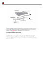
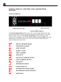
1
owner’s manual
Table of Contents
Page
WELCOME
1
WHAT’S NEW IN THE Z4
2
SAFETY INSTRUCTIONS
3
GETTING STARTED
4
SETTING UP THE ZENDRUM TO PLAY
6
DIGITAL DISPLAY, CONTROL PAD, AND SUSTAIN BUTTON
8
FUNCTIONS
11
FACTORY PRESET NOTE MAP LIST
19
TECHNICAL SPECIFICATIONS
20
APPENDIX
GENERAL MIDI
PERCUSSION NOTES
ZENDRUM MIDI IMPLEMENTATION CHART
GENERAL MIDI DRUM MAP
GARAGE BAND DRUM MAP
EZ DRUMMER DRUM MAP
21
21
23
24
25
26
27
WARRANTY
28
1
WELCOME
Thank you for purchasing your Zendrum. The Zendrum is a hardware MIDI controller
that was designed and built by drummers to allow all musicians to find new avenues of
expression and creativity. Transportation and set-up cease to be a time-consuming chore,
recording projects can be performed in the studio control room through the monitor
speakers, and the Zendrummer can now move to the front of the stage!
Please take time to read this manual. We have made every effort to design a user-friendly
instrument. Because it is a MIDI device, there are certain rules that will need to be
understood to avoid “user-error” and frustration. KNOW THIS – We, the inventors, are
drummers. We would rather play than program or read manuals. We’ll do our best to
make the instructions short and to the point, and get you up and running with the least
amount of “gear fear”. You can help by looking over this manual as you get started. If
you’re a first-time electronic musician, read ALL of the manual. It’s not long, and we’ll
try to give you tips while you’re learning so it will make logical sense.
We recommend reading the “Getting Started” section for anyone. It’s to your advantage
to understand the basics as you unpack your instrument and cable up for the first time.
The goal is to get you safely and surely playing as soon as possible without a lot of headscratching or guessing. Any tech support questions can be directed to:
www.zendrum.com
[email protected]
(404) 352-1646
Keep your sales receipt, shipping box, and manual.
For your future reference:
SERIAL NUMBER:
DATE OF PURCHASE:
____________________
____________________
2
WHAT’S NEW IN THE Z4
The Zendrum Z4 Series represents a huge step forward in precision, speed,
resolution, and dynamic articulation. The Zendrum was already the perfect MIDI
percussion controller for both hardware and software instruments. Now with the
new Z4 upgrade, the best has just gotten even better!
The new Dedicated Save Function makes it much easier to try out edits before
committing them. You can change several parameters of a preset then simply revert back
to the previously saved version with ease. Or you can easily commit the changes to be
there when you fire the Zendrum back up.
The new MIDI Channel-Per-Trigger Feature has vastly opened up the programming
options. Now you can control multiple Virtual Studio Technology (VSTi) instruments
with one preset. You can set up some triggers to play drums, some to control a soft synth,
and still others to fire off audio loops in your VSTi host...all simultaneously! New Hi-hat
Pedal Control Input, Volume Pedal Control Input and additional trigger pad
capability maximize today’s software and hardware.
Now, you can hear as well as see MIDI note number changes with the new Audible Note
Assignment Feature, which allows you to hear note changes as you scroll through the
MIDI note numbers.
The new Automatic Calibration Feature allows you to physically set the minimum and
maximum touch of each trigger and pedal.
Most importantly, the playing "feel" has been improved. It was already the best of
any MIDI controller out there, but the designers at Zendrum have managed to make it
even more "live" feeling with a state-of-the-art processor and advanced circuitry. The
Zendrum was already able to detect even the softest of hits, and now it picks up every
single stroke and nuance of even 32nd note and 64th note finger rolls. It's like you’re
touching the sounds themselves! There is no other controller on the market that can equal
the Zendrum’s touch sensitivity and quality construction.
3
SAFETY INSTRUCTIONS
1.
2.
3.
4.
5.
6.
Read and understand all instructions.
Follow all warnings and instructions marked on the product.
Unplug Zendrum from power source before cleaning.
Clean with a soft, dry cloth for fingerprints. DO NOT USE WET CLEANERS.
Do not place the Zendrum where it may fall.
Do not attempt to replace the 12V DC transformer without first contacting
Zendrum Technical Support.
7. Do not allow anything to rest on the power or MIDI cords.
8. Do not attempt to open backplate without qualified assistance from Zendrum
Technical Support.
9. Do not tamper with circuitry, wiring, or components. Doing so will void your
warranty.
PLEASE USE COMMON SENSE! The Zendrum is an electrical device.
Zendrum Technical Support
[email protected]
404-352-1646
4
GETTING STARTED
A Brief Overview of the Zendrum
The Zendrum is a MIDI (Musical Instrument Digital Interface) triggering controller
designed by drummers to allow musicians to express their creativity in rhythmic and
intuitive ways. However, the Zendrum can trigger ANY sound via MIDI, so it is much
more than drums yet as easy to play as tapping your desk with your fingers. Unlike a
keyboard, there are no moving parts to break or wear out. Anyone can enjoy it, but it is
not a toy. It is a real instrument carved and handcrafted from fine woods, assembled and
tested by the inventors. Each Zendrum is a work of art, manufactured with careful
attention to detail and high quality.
Remember, this is a Zendrum. You CAN hit it hard, but you don’t HAVE TO in order to
get the maximum dynamic MIDI volume. The louder you monitor yourself through
speakers or headphones, the lighter and more intricate your touch can become through
practice.
5
Basic Programming Functions
The Zendrum was designed by drummers to access the vast array of MIDI sounds. To
maximize the compatibility with other manufacturers’ MIDI devices, a certain number of
user-definable parameters were necessary.
One of the most basic programming functions is the MIDI Channel Select. CH
Matching the transmitting channel of the Zendrum to the receiving channel of the
hardware or computer interface is what makes it possible for them to communicate with
each other.
The other most basic programming function is the MIDI Note Select NO.
Each trigger can have a MIDI note number between 0 and 127 for each of the 16 Setup/note maps. This can be used to designate chord changes or change the playing position
of drum sounds. Most hardware drum sound modules have a range of 61 MIDI notes per
drum kit, any of which may be assigned to any Zendrum trigger you wish by changing
that trigger’s MIDI note to match. You can save any changes you make permanently
using the dedicated SAVE feature.
Dynamic Response Features
The Zendrum is the most dynamically expressive touch controller ever created. It has
several functions that combine to allow the user to tailor the touch response to personal
preferences.
The Noise Floor Function FL allows the user to set the minimum touch required to his
or her own personal hand strength and dexterity, while also setting a threshold so that
accidental vibrations or loud sound will not trigger false signals.
The MIDI Volume Function UL allows the user to set the maximum velocity sent by
the Zendrum. The combination of this parameter with the Noise Floor function sets the
Zendrum’s full dynamic range from soft to loud. The widest dynamics can occur when
the volume is maxed at 127 and the noise floor is at zero.
The Variable Velocity Response Curve Function rC lets the user choose between seven
different logarithmic response curves to create the best feel for his or her hardware or
computer generated sounds.
6
SETTING UP THE ZENDRUM TO PLAY
MERGE BRICK
The Zendrum Merge Brick combines the 12V DC transformer power with the MIDI
signal coming from the Zendrum using one all-pins active MIDI cable (supplied),
eliminating any extra cable connection to the Zendrum for power. The Merge Brick is a
sturdy metal box with an LED power indicator which has a MIDI IN port, a MIDI OUT
port, and a locking power input.
MIDI CABLES
You were supplied 2 all-pins active MIDI cables with your Zendrum. They are easily
identified by their longer length. You also received a 3’ MIDI cable that is only threepins active. This shorter cable should only be used between the MIDI OUT of the
Merge Brick and the MIDI IN of your hardware module or computer interface.
This cable WILL NOT power the Zendrum.
POWER SUPPLY
You received a 12 volt DC power supply rated at 800 mA with a positive center pin along
with your Zendrum. Please use ONLY THIS SUPPLY to power your Zendrum.
Please contact Zendrum Technical Support for replacement information.
POWERING UP THE ZENDRUM (see figure 1)
1. Connect the 15’ or 45’ all-pins active MIDI cable from the MIDI OUT port of the
Zendrum to the MIDI IN port of the Merge Brick.
2. Connect the 3’ three-pin active MIDI cable from the MIDI OUT of the Merge
Brick to your hardware module or computer interface.
3. Connect the 12V power supply pin to the Merge Brick power input and screw
locking mechanism from power supply pin on to Merge Brick power input jack to
lock in place.
4. Plug the 12V power supply into your electrical outlet and you are ready to begin.
7
Once the Zendrum is connected and powered up, its internal processor runs a series of
checks, flashes all the current settings on the digital display and comes to rest on the
Program Change Pr function. The Zendrum is now ready to play.
OTHER REQUIRED EQUIPMENT
In order to trigger sounds with the Zendrum, you must also have a hardware sound
module, drum machine, keyboard, or a computer with a MIDI/USB or Firewire
connection and sound card. You will also need headphones or an amplifier and speakers
to hear yourself play.
8
DIGITAL DISPLAY, CONTROL PAD, AND SUSTAIN
BUTTON
DIGITAL DISPLAY
The Zendrum digital display allows you to view current settings and functions, and
perform custom edits. It is a three-character alphanumeric display with two extra LED
indicator lights. The larger LED (Mode Change Light) to the left indicates Mode
Changes for each function, while the smaller LED indicator (Note-on Light) to the right
blinks whenever a MIDI message is sent. Each menu function is denoted by a twocharacter abbreviation (see below).
UP
Pr
UL
FL
CH
NO
dF
CP
PL
rC
Fd
Ed
Er
bC
SETUP/MEMORY BANK
PROGRAM CHANGE
MAX VOLUME
NOISE FLOOR
MIDI CHANNEL
MIDI NOTE
DEFAULT CURRENT SETUP
COPY CURRENT SETUP
POLARITY
RESPONSE CURVE
FORCE DISPLAY
SYSTEM EXCLUSIVE DUMP
SYSTEM EXCLUSIVE RECEIVE
MIDI BANK
9
Sd
S?
SA
d?
CI
C2
[]
FI
SAVE/DISCARD
SAVE?
SAVE ACCEPTED
DISCARD?
CALIBRATE MINIMUM
CALIBRATE MAXIMUM
SELECT BRACKETS
FACTORY INITIALIZE
CONTROL PAD/CURSOR SWITCH
The purpose of the control pad/cursor switch is to allow you to edit functions.
All functions of the Zendrum are selected and edited using the 4-button control
pad/cursor switch and shown on the digital display. You can press and hold any
button to scroll quickly in any direction for fast edits. Left and right buttons display
letters as the function abbreviations, + and – change/edit the numbers.
Selecting Functions
Press either left (I) or right (J) control button to access each specific Function page.
You can press and hold either button to scroll quickly.
Editing Functions
Press either the increment (+) or decrement (-) control button to see/change numeric
value of any function. You can press and hold either button to edit numbers quickly.
10
Any time an edit is made, the larger LED (Mode Change Light) to the left of the
digital display will begin blinking continuously to remind you to *save your edits*
before you power down or they will be lost. Any edits you make are active when you
change the numbers, but nothing is ever saved until you intentionally save it.
Saving Edits
Press the right (J) control button to the Save/Discard Sd display page.
Press (+) once to show blinking S?
Press (+) again to SAVE your changes.
Save Accepted SA display will flash once and then automatically return to Program
Change Pr display. The larger LED (Mode Change Light) to the left of the digital
display will stop blinking after your edits have been successfully saved.
To exit without saving, press left or right. Any edits you make are active when you
change the numbers, but nothing is ever saved until you intentionally save it.
Discarding Edits
Press the right (J) control button to the Save/Discard
Sd display page.
Press (-) once to show blinking d?
Press (+) to DISCARD your changes and revert back to previously saved edits.
The smaller LED (Note-On Light) will blink once and then automatically return to
Program Change Pr display. The larger LED (Mode Change Light) to the left of the
digital display will stop blinking after your edits have been successfully discarded.
SUSTAIN BUTTON
The Momentary Sustain Switch can be designated as either a Sustain or a Damper,
depending on its polarity. You can change its polarity from 0 (sustain) to 1 (damper)
using the Polarity PL function in the Functions Menu. It can also perform other
functions as well as sustaining notes with cc #64. (See Advanced User-Definable
Calibration)
11
FUNCTIONS
This section will walk you through the purpose and editing process of each function of
the Zendrum.
UP SETUP/MEMORY BANK (1-16)
There are 16 memory banks in the Zendrum called Setups UP. Each one of the 16
setups is comprised of ten functions: Program Change Pr, Max Volume UL, Noise
Floor FL, MIDI Channel CH, MIDI Note NO, Default Current Setup dF, Copy
Current Setup CP, Polarity PL, Response Curve rC, and MIDI Bank bC.
Access the Setup UP function of the Zendrum by pressing the left (I) button on the
control pad once when the Zendrum is on Program Change Pr. Scroll through setups
1-16 by pressing (+) or (-) and choose which setup you want to use by pressing left (I)
or right (J). Once you have selected a setup as the current one, you can begin editing
each function in that setup by scrolling to the right to view, then using +/- to make
numeric changes.
Pr PROGRAM CHANGE
(0 -127)
The purpose of the MIDI Program Change Pr function is to select an entire instrument
sound or “voice” remotely from the Zendrum. For example, this could be an entire
drumkit patch or a piano voice from a hardware sound module, or a performance patch
from a VST instrument. The MIDI Program Change numerical values range from 0 to
127 and must be matched with the numerical value for the instrument voice you want to
play within your hardware or software. While in Program Change Pr, you can select
the numerical value of your program by pressing (+) or (-) and then pressing left (I) or
right (J) to send the program change.
UL MAX VOLUME (0 -127, Default =127)
The purpose of the Max Volume UL function is to scale the maximum velocity that the
triggers can send to your MIDI device. This is where you can adjust the peak levels of an
entire instrument sound and “squeeze” its dynamic output. For widest possible playing
range from soft to loud leave Max Volume at 127. When set to maximum the actual
strike velocity will be sent. When set below maximum the velocity will be scaled. If the
volume is set to 64 = 1/2 then a maximum strike which would normally send a value of
127 will send a value of 64 and a medium strike that would normally send a value of 64
will send a value of 32, etc. This max velocity/volume is stored in the currently selected
setup ONLY. You must save it using the Save/Discard Sd function.
12
FL NOISE FLOOR (0-127, default=6)
The purpose of the Noise Floor FL function is to establish the minimum force required
to trigger a note while preventing vibrations or loud sound from sending unintentional
notes by setting a threshold below which nothing will be sent. This function is important
when considering that all software and hardware devices have limits of polyphony or
simultaneous voices that they can process and respond to. Without the correct noise floor,
the Zendrum’s hypersensitivity could cause it to send too many simultaneous “ghost”
notes and overwhelm the sound device’s simultaneous voice capacity (polyphony)
causing all the sounds to be clipped or chopped off. Carefully setting this level will help
to streamline the communication between the Zendrum and your other devices and
allow the Zendrum Display to show ONLY the exact notes you intend to edit. For
best dynamic range leave the noise floor as low as possible, but high enough so that false
triggering does not occur. One increment either way makes a noticeable and audible
difference, so make changes sparingly from the default of 6 and test thoroughly before
you permanently save to the currently selected Set up UP using the Save/Discard Sd
function .
CH MIDI CHANNEL (1-16)
The purpose of the MIDI Channel CH function is to match the MIDI channel of the
Zendrum with the MIDI channel of your hardware or software program. This is what
allows MIDI devices to communicate with each other properly. There are 16 MIDI
channels available. General MIDI specifications (see Appendix section) designate
channel 10 as the drum channel, and for this reason, your Zendrum is factory preset to
power up with Setup number 16 on Channel 10 to work with the vast majority of drum
map programs. You can change this number to whatever you like. There is also an
individual MIDI channel per trigger feature that may be stored as part of each of the 16
setups (see MIDI-Channel Per Trigger Feature)
While in the MIDI Channel CH function, press (+) once to view your current MIDI
channel. Use (+) or (-) to select your MIDI channel, and then press left (I) or right
(J ) to send the change.
MIDI CHANNEL PER TRIGGER FEATURE
The purpose of the MIDI Channel Per Trigger feature is to designate “trigger zones”,
or groups of triggers, on the Zendrum to play different instruments, or “voices” at the
same time using different MIDI channels. For instance, you can have a group of triggers
for drums, another group for piano, and another group for guitars all at the same time.
While in the MIDI Channel CH function, press (+) and (-) simultaneously to show
the Select Brackets [ ]. Tap each trigger and use (+) or (-) to change the numeric value
to the channel you wish to assign to that trigger, and then press left (I) or right (J ) to
send the change. Save to the currently selected Set up UP using the Save/Discard Sd
function.
13
NO MIDI NOTE (0-127)
The purpose of the MIDI Note NO function is to assign individual drums or melodic
notes to each trigger. The standard numeric value ranges from 0 to 127. However, the
Zendrum allows for a 4-note sequential velocity switch per trigger. (see 4-Note Velocity
Switch Feature)
While in the MIDI Note NO function, press (+) or (-) to show the Select Brackets [ ].
Tap the trigger you wish to change once, then use (+) or (-) to change the numeric value
of that trigger. You will hear the sound that corresponds to that MIDI note number as you
scroll through the numbers with the new Audible Note Assignment feature of the Z4.
4-NOTE VELOCITY SWITCH FEATURE
The purpose of the 4-Note Velocity Switch feature is to allow for the most realism and
articulation of each trigger when using drum libraries. It sends four sequential MIDI
notes when played soft to loud to take advantage of multi-sampled articulations such as
hi-hat and snare drum sounds. For instance, you can designate a different sound for soft,
medium, loud, and hot on each trigger based on the realistic sound dynamics of a drum or
cymbal. A snare drum trigger can start as a “brush hit” sound for soft, to a “bamboo rod”
hit sound for medium, to a “middle-of-the-head hit” sound for loud, to a “rim shot” sound
for hot. A hi-hat trigger can start as a foot pedal “chick” sound for soft, to a “stick tip”
sound for medium, to a “stick shank” for loud, finally to a wide open “wash” sound for
hot. The same principle applies to any MIDI sound where you would want to designate
four sequential notes to be activated by one trigger. As long as the 4 MIDI notes are in
numerical sequence (for example 40-41-42-43) you can designate blocks of four
notes to any trigger.
To access the 4-Note Velocity Switch feature, and while in the MIDI Note NO
function, press (+) or (-) to show the Select Brackets [ ]. Tap ONLY the trigger you
wish to change, then use (+) or (-) to change the numeric value of that trigger. If you
scroll up PAST 127, the large LED (Mode Change Light) to the left of the digital
display will come on and the numbers will start over again at zero. Now you are in 4Note Velocity Switch mode and whichever MIDI note you stop on (between 0 and 124)
will be the first note of the 4 sequential notes that you can assign to any trigger.
4-Note Velocity Switch Points
0
65
85
105
127
[______________________________l____________l_____________l___________]
min
SOFT
MEDIUM
LOUD
HOT! max
Note and sound #1
#2
#3
#4
14
dF DEFAULT CURRENT SETUP
The purpose of the Default Current Setup dF function is to overwrite any edits within
the currently selected setup, and revert back to the original factory presets for that setup.
(see Appendix section)
To default, while in the Default Current Setup dF function, press and hold (+). The
digital display will blink the number of the current setup. Hold (+) until the number stops
blinking. You can store this edit using the Save/Discard Sd function.
CP COPY CURRENT SETUP
The purpose of the Copy Current Setup CP function is to copy the currently selected
setup and clone it to another setup number 1-16. This will overwrite any information in
the setup that you select as the additional location.
To copy from the current setup, press (+) or (-) to select another location for the cloned
setup. Then scroll right (J) to the Save/Discard Sd function and save the change.
PL POLARITY (0-1)
The purpose of the Polarity PL function is primarily to allow you to set the
Momentary Sustain Button to act either an All-Notes Off Damper Switch or a Sustain
Switch. In other words, you can use the button to hold out (sustain) the melodic notes
you play, or the melodic notes you play can ring out until you press the button to stop
(damper) them. The button’s default status is set to 0 for sustain.
To change the Momentary Sustain Button’s functionality from sustain to damper, while
in the Polarity PL function, press (+) and change polarity from 0 (sustain) to 1
(damper).
15
rC RESPONSE CURVE (0-7)
The purpose of the Response Curve rC function is allow you to tailor the touch
response of the Zendrum triggers to suit your personal playing style and get the best
dynamic range from your particular sound source. Each MIDI device will have a certain
“feel” to its dynamics. We encourage you to experiment with all seven different variable
velocity Response Curves to find what makes your sound source interact to your liking
with the Zendrum triggers.
While in the Response Curve rC function, press (+) or (-) to select a Response Curve.
Then scroll right (J) to the Save/Discard Sd function and save the change. The curves
are numbered 0-7 and can be described as follows:
0 Unaffected
1 A little faster rise through the middle velocity range
2 Slightly faster to rise than 1
3 Most accelerated through the middle velocity range
4 slower rise than 0 through the middle velocity range (decelerated)
5 Slightly slower rise than 4
6 Slowest through the middle velocity range
7 All hits max at 127 (Good for setting mixer input levels or positive control of loops)
16
Fd
FORCE DISPLAY
While in the Force Display Fd function, press (+) to activate the Visual Force
Display. Tap each trigger to view the relative strength of each hit.
Ed SYSTEM EXCLUSIVE DUMP (SYSEX)
The purpose of the System Exclusive Dump Ed function is to send the entire memory
of the Zendrum to another Zendrum or a computer for data backup. This will require a
SYSEX librarian program or another Zendrum to be connected via MIDI.
Once connected, and while in the System Exclusive Dump Ed function, press (+) to
tell the Zendrum to send bulk data. The display will flash until the data has been sent.
Er SYSTEM EXCLUSIVE RECEIVE (SYSEX)
The purpose of the System Exclusive Receive Er function is to receive data sent from
another Zendrum or computer SYSEX librarian program. This will require a SYSEX
librarian program or another Zendrum to be connected via MIDI.
Once connected, and while in the System Exclusive Receive Er function, press (+) to
tell the Zendrum to receive incoming bulk data. The display will flash Er until the data
has been received through the MIDI in port of the Zendrum. Then, scroll right (J) to the
Save/Discard Sd function and save the data.
bC MIDI BANK (0-127)
The purpose of the MIDI Bank bC function is to allow compatibility with hardware
sound modules that support more than 127 MIDI sounds. Each group of 127 sounds must
be designated as “banks” by your hardware sound module or keyboard in order to be
accessed by the Zendrum using this function. MIDI specifications allow for 127 banks,
each with up to 127 sounds. Consult the owner’s manual of your hardware sound
module or keyboard for specific bank/program numbers of each sound you wish to
access with the Zendrum.
While in the MIDI Bank bC function, press (+) or (-) to select bank number from 0 to
127 that corresponds with the bank number table of your hardware. Then scroll right (J)
to the Save/Discard Sd function and save the data.
17
FI FACTORY INITIALIZE
This feature allows you to overwrite all of your edits and revert back to the factory
presets (see Appendix section) on all 16 setups at once. To access this feature, while
powering up the Zendrum, hold (+) and (-) on the control pad until the digital display
starts flashing FI. Then release the buttons and scroll right (J) to the Save/Discard
Sd function and save the re-initialized data.
ACCESSING EMBEDDED SERIAL NUMBER
To access embedded Serial Number, while in the Program Change Pr function, press
and hold right (J) on the control pad until the number “41” appears flashing on the
digital display. This denotes the Zendrum Z4 processor (version 4.1). The next four
pairs of digits that appear on the digital display are your 8-digit serial number.
FAIL-SAFE LOCK/UNLOCK
This feature is useful for letting someone try out your Zendrum without overwriting your
edits. Fail-Safe Lock/Unlock prevents anyone from changing your settings.
To Lock your Zendrum, press and hold left (I) and right (J) simultaneously until the
digital display stops flashing and the large LED (Mode Change Light) to the left comes
on. Now your Zendrum is locked.
To Unlock your Zendrum, press and hold left (I) and right (J) simultaneously until the
digital display stops flashing and the large LED (Mode Change Light) to the left goes
off. Now your Zendrum is unlocked.
ADVANCED USER-DEFINABLE CALIBRATION
The Z4 allows for Variable Input Devices such as hi-hat and volume pedals to send
changes that can be used to modify sounds. The Zendrum must read the output voltage
and polarity, then scale the value from 0-127 in MIDI to have any changes that are read
control a function, so you must first calibrate the input device and train it to operate
properly.
All physical devices are different. Every Zendrum trigger may have a slight difference in
output from one to another. You can now also add extra triggers or pedals to the Z4
Zendrum that may have widely different output values, even if they are made by the same
manufacturer. Your Zendrum was calibrated by David Haney in final testing for peak
performance, however if you add input devices or just want to try tweaking the
'feel', calibration is the place to start. Remember you can experiment and tweak and
adjust settings and/or calibrate and then save OR discard the results using the Sd
function.
18
To begin a calibration make sure all variable input devices such as
pedals/knobs/sliders/wheels/joysticks are at their minimum position.
Use the left/right keys to move to PL and then press (+) and (-) simultaneously. The
display will change to a blinking CI. During this time Zendrum is learning the
minimum value of each input. You may want to bang on the body (not the triggers) to
teach Zendrum to ignore false body blows. Do not move variable input devices
during the CI portion of calibration.
From the blinking CI display again press (+) and (-) simultaneously. The display will
change to a blinking C2. During this time Zendrum is learning the active maximum
value of each trigger and connected variable device. Now is the time to beat triggers and
press/turn/slide each variable device to its maximum position a few times. You don't
have to hold anything as Zendrum remembers the maximum value it reads during the
C2 portion of calibration.
From the blinking C2 display again press (+) and (-) simultaneously. Zendrum now
uses the learned values to automatically determine the polarity and active range of
each input. If any input (trigger or variable) was left alone during the calibration
process, its values are not changed.
If you want to abort the calibration process (if you accidentally hit trigger pads during
CI or forgot to move a variable device to minimum position before CI began) you can
use the left or right arrow keys to exit and nothing will be changed.
When you like everything you’ve done remember to save. The saved polarity and
min/max values learned during calibration will be used for all of your setups.
CC MESSAGE NUMBER
This tells the Zendrum what control change message to send from your pedal, etc. to have
it act as a hi-hat, volume, expression, or any other MIDI change command that your
sounds can recognize. The CC message number is assigned in the MIDI Note NO
function.
To set CC message number for an input device, while in MIDI Note NO function,
press (+) to show Select Brackets [ ]. Move device to show current message number
on the digital display. The default CC message number is either 3 or 9, which are
generally unassigned numbers. You must edit this number to assign the specific task you
want the input device to control. The most commonly used message number for
controlling hi-hat sounds is number 4 (expression). The most commonly used message
number for controlling volume is number 7 (volume). Consult the owner’s manual of
your sound device for specific information regarding its accessible recognized CC
Messages.
19
FACTORY PRESET NOTE MAP LIST
UP function. Each can be
edited to your preferences. You can save these edits using the Save/Discard Sd
The factory preset note maps are accessed within the Setup
function. The Setups are factory preset to correspond to the following melodic scales and
General MIDI drum maps:
1. C Pentatonic
2. C Minor
3. Ionian Major Mode
4. Dorian Mode
5. Phrygian Mode
6. Mixolydian Mode
7. Aeolian Mode (natural minor)
8. Harmonic Minor
9. Chromatic
10. Whole Tone
11. Blues
12. Minor Thirds
13. Eastern
14. General MIDI Drum Map
15. General MIDI Drum Map
16. General MIDI Drum Map
20
TECHNICAL SPECIFICATIONS
Body
Triggers
Note Maps
Operating System
Display
Global Parameters
Trigger Parameters
MIDI
Ports
Power
Solid rock maple and exotic hardwoods in clear wood stains
24 velocity-sensitive, shock-mounted
16 user-definable set-ups
4-way Cursor Switch
Momentary Sustain Switch
3-digit, 7-segment LED
MIDI Volume: 0-127
MIDI Channels: 1-16
Program Change: 0-127
Noise Floor: 0-127
System Exclusive Receive (SYSEX)
System Exclusive Send (SYSEX) (Bulk Dump)
Copy Set-up: 1-16
Restore Defaults: 1-16
Force Display VU Meter
Variable Velocity Response Curves: 1-7
Bank Select: 0-127
Save/Discard
MIDI Note Number: 0-127
4-way Velocity Switch: 0-124
MIDI Channel-per-trigger
Transmits on all 16 Channels, one channel per trigger or
globally (one channel per setup)
MIDI IN
MIDI OUT
Continuous Controller Pedal IN
External Foot Trigger IN
12VDC Power/Merge Brick sends power to Zendrum via 5pin active MIDI cable (supplied)
21
APPENDIX
GENERAL MIDI
General MIDI or GM is a standardized specification for music synthesizers that respond
to MIDI messages. GM was developed by the MIDI Manufacturers Association (MMA)
and the Japan MIDI Standards Committee (JMSC) and first published in 1991. The
official specification is available in English from the MMA, bound together with the
MIDI 1.0 specification, and in Japanese from the Association of Musical Electronic
Industry (AMEI).
GM imposes several requirements beyond the more abstract MIDI 1.0 specification.
While MIDI 1.0 by itself provides a protocol which ensures that different instruments can
interoperate at a fundamental level (e.g. that pressing keys on a MIDI keyboard will
cause an attached MIDI sound module to play musical notes), GM goes further in two
ways: it requires that all GM-compatible synthesizers meet a certain minimal set of
features, such as being able to play at least 24 notes simultaneously (polyphony), and it
attaches specific interpretations to many parameters and control messages which were
left under-specified in the MIDI 1.0 spec, such as defining instrument sounds for each of
the 128 possible program numbers.
GM synthesizers are required to be able to:
•
•
•
•
Allow 24 voices to be active simultaneously (including at least 16 melodic and 8
percussive voices)
Respond to note velocity
Support all 16 channels simultaneously (with channel 10 reserved for percussion)
Support polyphony (multiple simultaneous notes) on each channel
Program change events
In MIDI, the instrument sound or "program" for each of the 16 possible MIDI channels is
selected with the Program Change message, which has a Program Number parameter.
The following table shows which instrument sound corresponds to each of the 128
possible Program Numbers for GM only. Note that for purposes of computer
programming, this table should start at 0 instead of 1 and thus use all of the 7-bit range
(0-127) allowed by the MIDI Program Change message. It should also be noted that some
MIDI keyboards display these Program Numbers as shown in the table (1-128), whereas
others show the range as actually coded in the Program Change message (0-127).
22
MELODIC SOUNDS
Piano:
1 Acoustic Grand Piano
2 Bright Acoustic Piano
3 Electric Grand Piano
4 Honky-tonk Piano
5 Electric Piano 1
6 Electric Piano 2
7 Harpsichord
8 Clavinet
Chromatic Percussion:
9 Celesta
10 Glockenspiel
11 Music Box
12 Vibraphone
13 Marimba
14 Xylophone
15 Tubular Bells
16 Dulcimer
Organ:
17 Drawbar Organ
18 Percussive Organ
19 Rock Organ
20 Church Organ
21 Reed Organ
22 Accordion
23 Harmonica
24 Tango Accordion
Guitar:
25 Acoustic Guitar (nylon)
26 Acoustic Guitar (steel)
27 Electric Guitar (jazz)
28 Electric Guitar (clean)
29 Electric Guitar (muted)
30 Overdriven Guitar
31 Distortion Guitar
32 Guitar harmonics
Bass:
33 Acoustic Bass
34 Electric Bass (finger)
35 Electric Bass (pick)
36 Fretless Bass
37 Slap Bass 1
38 Slap Bass 2
39 Synth Bass 1
40 Synth Bass 2
Strings:
41 Violin
42 Viola
43 Cello
44 Contrabass
45 Tremolo Strings
46 Pizzicato Strings
47 Orchestral Harp
48 Timpani
49 String Ensemble 1
50 String Ensemble 2
51 Synth Strings 1
52 Synth Strings 2
53 Choir Aahs
54 Voice Oohs
55 Synth Voice
56 Orchestra Hit
Brass:
57 Trumpet
58 Trombone
59 Tuba
60 Muted Trumpet
61 French Horn
62 Brass Section
63 Synth Brass 1
64 Synth Brass 2eed:
65 Soprano Sax
66 Alto Sax
67 Tenor Sax
68 Baritone Sax
69 Oboe
70 English Horn
71 Bassoon
72 Clarinet
Pipe:
73 Piccolo
74 Flute
75 Recorder
76 Pan Flute
77 Blown Bottle
78 Shakuhachi
79 Whistle
80 Ocarina
Synth Lead:
81 Lead 1 (square)
82 Lead 2 (sawtooth)
83 Lead 3 (calliope)
84 Lead 4 (chiff)
85 Lead 5 (charang)
86 Lead 6 (voice)
87 Lead 7 (fifths)
88 Lead 8 (bass + lead)
Synth Pad:
89 Pad 1 (new age)
90 Pad 2 (warm)
91 Pad 3 (polysynth)
92 Pad 4 (choir)
93 Pad 5 (bowed)
94 Pad 6 (metallic)
95 Pad 7 (halo)
96 Pad 8 (sweep)
Synth Effects:
97 FX 1 (rain)
98 FX 2 (soundtrack)
99 FX 3 (crystal)
100 FX 4 (atmosphere)
101 FX 5 (brightness)
102 FX 6 (goblins)
103 FX 7 (echoes)
104 FX 8 (sci-fi)
Ethnic:
105 Sitar
106 Banjo
107 Shamisen
108 Koto
109 Kalimba
110 Bag pipe
111 Fiddle
112 Shanai
Percussive:
113 Tinkle Bell
114 Agogo
115 Steel Drums
116 Woodblock
117 Taiko Drum
118 Melodic Tom
119 Synth Drum
Sound effects:
120 Reverse Cymbal
121 Guitar Fret Noise
122 Breath Noise
123 Seashore
124 Bird Tweet
125 Telephone Ring
126 Helicopter
127 Applause
128 Gunshot
23
PERCUSSION NOTES
GM Standard Drum Map
In GM, MIDI channel 10 is reserved for percussion instruments only. Notes played on channel 10 always
produce percussion sounds regardless of any Program Change messages or Program Numbers that may
have been sent on channel 10. Each of the 128 different possible note numbers is interpreted as a separate,
different instrument, and the percussion sound's pitch is not related to the note number:
35
36
37
38
39
40
41
42
43
44
45
46
47
48
49
50
51
52
53
54
55
56
57
58
Bass Drum 2
Bass Drum 1
Side Stick
Snare Drum 1
Hand Clap
Snare Drum 2
Low Tom 2
Closed Hi-hat
Low Tom 1
Pedal Hi-hat
Mid Tom 2
Open Hi-hat
Mid Tom 1
High Tom 2
Crash Cymbal 1
High Tom 1
Ride Cymbal 1
Chinese Cymbal
Ride Bell
Tambourine
Splash Cymbal
Cowbell
Crash Cymbal 2
Vibra Slap
59
60
61
62
63
64
65
66
67
68
69
70
71
72
73
74
75
76
77
78
79
80
81
Ride Cymbal 2
High Bongo
Low Bongo
Mute High Conga
Open High Conga
Low Conga
High Timbale
Low Timbale
High Agogo
Low Agogo
Cabasa
Maracas
Short Whistle
Long Whistle
Short Guiro
Long Guiro
Claves
High Wood Block
Low Wood Block
Mute Cuica
Open Cuica
Mute Triangle
Open Triangle
24
ZENDRUM MIDI IMPLEMENTATION CHART
Function
Transmitted
Default Channel
1-16
X
Stored
Basic channel
1-16
X
Stored
Mode:
Default
Messages
Altered
Note Number:
True Voice
Recognized
Remarks
X
X
X
X
X
X
0-127
X
Stored
O
O
X
X
Note off
immediately
follows note
on @ 10ms
Aftertouch
Keys
Channel
X
X
X
X
Pitch Bend
X
X
O
X
Sustain
button
CC input
0-127
X
Stored
O
O
X
X
X
X
X
X
X
X
X
X
X
X
X
X
X
X
X
X
Velocity Note On
Note Off
Control Change: 64
Control Change 0-31,64127
Program Change:
True Number
Notes:
O = YES
X = NO
Mode 1: OMNI ON. POLY
Mode 2: OMNI ON. MONO
Mode 3: MONO OFF. POLY
Mode 4: OMNI OFF. MONO
Zendrum Corp.
Revision 4.1
System Exclusive
System: Song Pos.
Song Sel.
Common: Tune
System: Clock
Real Time:
Commands
Aux Messages:
Local On/OFF
All notes OFF
Active Sense
Reset
Zendrum MIDI Implementation Chart
6/15/09
**Sustain
Polarity is
selected and
stored
25
GENERAL MIDI DRUM MAP
26
GARAGE BAND DRUM MAP
27
EZ DRUMMER DRUM MAP
28
WARRANTY
The Zendrum is warranted “for life” (meaning David Haney’s lifetime, not yours)
from defects in workmanship, provided it has not been modified or abused. The
warranty is in effect as long as you are the original owner of this instrument. It is
the sole judgment of Zendrum Corporation to decide what constitutes abnormal
wear and tear. Tampering with circuit board or components will void your
warranty and could permanently damage your instrument.
This instrument is designed by drummers to be played vigorously with the hands. It
is not intended to be played with sticks, and doing so will ultimately void your
warranty as well as damage the body and triggers.
Should you EVER need service or upgrades, Zendrum is a user-friendly, personal
service-minded company. We personally stand behind every instrument we build,
and our good reputation depends on your satisfaction. We enjoy hearing from you.
We do not anticipate that you will ever experience mechanical failure, but if
problems do occur, we will be happy to troubleshoot, tech support, and repair your
instrument. You will be responsible for shipping charges, as well as customs, duties,
taxes, etc. where applicable. Zendrum will be responsible for parts and labor only.
PLEASE DIRECT ALL QUESTIONS AND CONCERNS TO ZENDRUM
TECHNICAL SUPPORT.
TECHNICAL SUPPORT
(404) 352-1646
www.zendrum.com
[email protected]