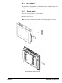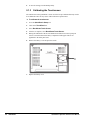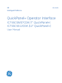
1
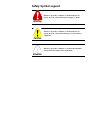
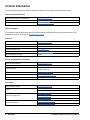
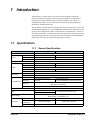
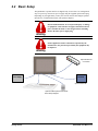
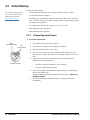
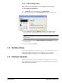
GE
Intelligent Platforms
GFK-2847B
QuickPanel+ Operator Interface
IC755CSW07CDA (7” QuickPanel+)
IC755CSS12CDA (12” QuickPanel+)
User Manual
These instructions do not purport to cover all details or variations in equipment, nor to provide for every possible
contingency to be met during installation, operation, and maintenance. The information is supplied for informational
purposes only, and GE makes no warranty as to the accuracy of the information included herein. Changes, modifications,
and/or improvements to equipment and specifications are made periodically and these changes may or may not be reflected
herein. It is understood that GE may make changes, modifications, or improvements to the equipment referenced herein or to
the document itself at any time. This document is intended for trained personnel familiar with the GE products referenced
herein.
GE may have patents or pending patent applications covering subject matter in this document. The furnishing of this
document does not provide any license whatsoever to any of these patents.
GE provides the following document and the information included therein as is and without warranty of any kind, expressed
or implied, including but not limited to any implied statutory warranty of merchantability or fitness for particular purpose.
For further assistance or technical information, contact the nearest GE Sales or Service Office, or an authorized GE Sales
Representative.
Revised: Mar 2014
Issued: Nov 2013
Copyright © 2013 - 2014 General Electric Company, All rights reserved.
___________________________________
* Indicates a trademark of General Electric Company and/or its subsidiaries.
All other trademarks are the property of their respective owners.
Refer to the section, Contact Information for support on this product.
Please send documentation comments or suggestions to [email protected]
Safety Symbol Legend
Indicates a procedure, condition, or statement that, if not
strictly observed, could result in personal injury or death.
Warning
Indicates a procedure, condition, or statement that, if not
strictly observed, could result in damage to or destruction of
equipment.
Caution
Indicates a procedure, condition, or statement that should be
strictly followed to improve these applications.
Attention
Contact Information
If you purchased this product through an Authorized Channel Partner, please contact the seller directly.
General Contact Information
Online technical support and GlobalCare
http://support.ge-ip.com
Additional information
http://www.ge-ip.com/
Solution Provider
[email protected]
Technical Support
If you have technical problems that cannot be resolved with the information in this manual, please contact us by
telephone or email, or on the web at http://support.ge-ip.com
Americas
Online Technical Support
http://support.ge-ip.com
Phone
1-800-433-2682
International Americas Direct Dial
1-780-420-2010 (if toll free 800 option is unavailable)
Technical Support Email
[email protected]
Customer Care Email
[email protected]
Primary language of support
English
Europe, the Middle East, and Africa
Online Technical Support
http://support.ge-ip.com
Phone
+ 800-1-433-2682
EMEA Direct Dial
+ 420-23-901-5850 (if toll free 800 option is unavailable or dialing from
a mobile telephone)
Technical Support Email
[email protected]
Customer Care Email
[email protected]
Primary languages of support
English, French, German, Italian, Czech, Spanish
Asia Pacific
Online Technical Support
Phone
http://support.ge-ip.com
+ 86-400-820-8208
+ 86-21-3217-4826 (India, Indonesia, and Pakistan)
[email protected] (China)
Technical Support Email
[email protected] (Japan)
[email protected] (remaining Asia customers)
[email protected]
Customer Care Email
4
GFK-2847B
[email protected] (China)
QuickPanel+ Operator Interface User Manual
Contents
1 Introduction ....................................................................................................................................... 7
1.1 Specifications .........................................................................................................................................7
1.1.1
General Specifications .......................................................................................................................7
1.1.2
Physical Specifications and Mounting ...................................................................................................8
1.1.3
Environmental Specifications ..............................................................................................................8
1.2 QuickPanel+ Hardware User Features..........................................................................................................9
1.2.1
Overview ........................................................................................................................................9
1.2.2
Status Indicators for IC755CSW07CDA and IC755CSS12CDA............................................................... 11
2 Getting Started ................................................................................................................................ 13
2.1 Unpacking and Inspection ....................................................................................................................... 13
2.2 Basic Setup .......................................................................................................................................... 15
2.3 Initial Startup ........................................................................................................................................ 16
2.3.1
Connecting Input Power ................................................................................................................... 16
2.3.2
Initial Configuration ........................................................................................................................ 17
2.4 Runtime Setup ...................................................................................................................................... 17
2.5 Firmware Updates.................................................................................................................................. 17
2.6 Shutdown............................................................................................................................................. 18
3 QuickPanel+ Software................................................................................................................... 19
3.1 Operating System .................................................................................................................................. 19
3.2 Backup Utility....................................................................................................................................... 19
3.3 Storage Manager ................................................................................................................................... 19
3.4 Copy Project to SD Card ......................................................................................................................... 20
3.5 Updating a Machine Edition Project .......................................................................................................... 21
3.6 FTP Server ........................................................................................................................................... 22
3.6.1
Authentication of Remote Users......................................................................................................... 22
3.6.2
FTP with Removable Flash Devices ................................................................................................... 22
3.7 HTTP Server ........................................................................................................................................ 22
4 Installation........................................................................................................................................ 23
4.1 Installing the Protective Sheet .................................................................................................................. 23
4.2 Choosing a Mounting Location................................................................................................................. 24
4.3 Panel Mounting ..................................................................................................................................... 25
4.4 Installation Procedure ............................................................................................................................. 26
4.5 Mounting on a VESA Arm ...................................................................................................................... 28
4.6 Installing and Replacing the Battery .......................................................................................................... 29
4.6.1
IC755CSW07CDA.......................................................................................................................... 29
4.6.2
IC755CSS12CDA ........................................................................................................................... 31
4.7 Connectors ........................................................................................................................................... 33
4.7.1
Power Connector Pin-out for IC755CSW07CDA and IC755CSS12CDA ................................................... 33
4.7.2
Ethernet for IC755CSW07CDA and IC755CSS12CDA.......................................................................... 33
GFK-2847B User Manual 5
4.7.3
Serial Port ..................................................................................................................................... 34
4.7.4
Universal Serial Bus (USB) Ports....................................................................................................... 35
4.7.5
Audio (LINE OUT) Details for IC755CSW07CDA and IC755CSS12CDA ................................................ 36
4.7.6
4.6.6 Audio (MIC IN) Details (only applicable to IC755CSW07CDA) ...................................................... 36
4.7.7
SD Card Slot .................................................................................................................................. 37
5 Detailed Operation ......................................................................................................................... 39
5.1 Touchscreen Display .............................................................................................................................. 39
5.1.1
Adjusting the Display Brightness ....................................................................................................... 39
5.1.2
Configuring the Backlight................................................................................................................. 39
5.1.3
Calibrating the Touchscreen .............................................................................................................. 40
5.2 Keyboard ............................................................................................................................................. 41
5.2.1
External Keyboard (Optional)............................................................................................................ 41
5.2.2
Soft Input Panel .............................................................................................................................. 41
5.3 Mouse ................................................................................................................................................. 41
5.4 Memory............................................................................................................................................... 42
5.4.1
DRAM Memory ............................................................................................................................. 42
5.4.2
Changing the Memory Allocation....................................................................................................... 42
Appendix A Product Certifications and Installation Guidelines............................................... 43
Appendix B Orderable Part Numbers.............................................................................................. 45
Index......................................................................................................................................................... 47
6
GFK-2847B
QuickPanel+ Operator Interface User Manual
1
Introduction
The QuickPanel+ operator interface is an all-in-one microcomputer designed for
maximum flexibility. The design, based on an advanced ARM core microprocessor,
brings together a high-resolution touchscreen operator interface with a variety of
communications options. You can connect to most industrial equipment through the
QuickPanel+ communications ports.
The QuickPanel+ operator interface is equipped with several memory types to satisfy the
most demanding applications. A section of DRAM is split between the operating system,
an object store and application memory. Functioning as a virtual hard drive, a section of
non-volatile flash memory is divided between the operating system and persistent storage
for application programs. The retentive memory consists of a battery-backed SRAM for
data storage, protecting your valuable data during a power failure.
1.1 Specifications
1.1.1 General Specifications
IC755CSW07CDA
Processor
Memory
IC755CSS12CDA
Freescale i.MX535 (1GHz ARM Cortex A8)
RAM
ROM
SRAM
Operating System
DDR2 SDRAM 512 MB
SLC NAND 256 MB
DDR3 SDRAM 1GB
SLC NAND 512 MB
512 KB (with Battery backup)
Microsoft Windows Embedded Compact 7
Type
Display
Touchscreen
Communications
7” Widescreen TFT LCD
12.1” Std TFT LCD
800(W) x 480(H) pixels WVGA
800(W) x 600(H) pixels SVGA
Resolution
65,536
Color
2
Brightness
310 cd/m
450 cd/m2
Backlight
LED
Touch Panel Type
Projected Capacitive
Two-point
Multi-touch
1x 10/100BaseT (RJ-45)
Ethernet Port
1x RS-232 UART Port (5-Pin
1x RS-232 UART Port,
Serial Port
Connector)
1x RS-232/422/485 Port (10-Pin Connector)
2x USB2.0 (Type-A)
USB, Host
Max. Power (5 V at 0.5 A)
1x USB 2.0 (Mini Type-B)
USB, Device
Storage
Audio
Noise Immunity
Input power
Introduction
Rated Voltage
Power
Consumption
Frame Ground
1x SD/SDHC Card Slot
1x Mic In (mono) (3.5 mm Jack)
1x Line Out (Stereo) (3.5 mm Jack)
1x Line Out (Stereo) (3.5 mm Jack)
Noise voltage: 1500 V p-p
Pulse Duration: 1µs, Rise time: 1ns
+24 V dc ±20% (3-Pin Connector)
+12/24 V dc ±20% (3-Pin Connector)
15 W (max), 0.625 A
30 W (max), 2.5/1.25 A
Frame GND is connected to Signal GND internally
GFK-2847B User Manual 7
1.1.2 Physical Specifications and Mounting
IC755CSW07CDA
IC755CSS12CDA
Dimensions (L×W×D)
192 × 137 × 36 mm
(7.56 × 5.39 × 1.42 in)
314 × 248 × 65 mm
(12.36 × 9.76 × 2.56 in)
Weight
0.800 kg (1.76 lbs)
3 kg (6.61 lbs)
Panel cutout
dimensions
183.5 ×128.5 mm
(7.22 × 5.06 in)
302 × 228 mm
(11.89 × 8.98 in)
VESA mount
75 x 75 mm
(2.95 x 2.95 in)
100 x 100 mm
(3.94 x 3.94 in)
Mounting
Options
1.1.3 Environmental Specifications
For additional product
standards and agency
approvals, refer to Appendix A.
Note The QuickPanel+ should be installed in a location that is well ventilated and not
exposed to dust, corrosive gases or liquids, flammable gases, rain, strong ultraviolet light
or direct sunlight, and that meets the environmental specifications listed in the following
table.
IC755CSW07CDA
Cooling
Ambient Operating
Temperature
IC755CSS12CDA
Natural convection
0 to +55°C (32 to 131 °F)
Ambient Storage
Temperature
-10 to +60°C (14 to 140 °F)
Ambient Humidity
(Operating and
Storage)
85% RH
Non-condensing, wet-bulb temperature: 30°C (86 °F) or less
Environment
Pollution Degree 2, Indoor use only
Vibration Resistance
5 to 9 Hz single-amplitude 3.5 mm (0.14 in)
9 to 150 Hz constant-accelerated velocity 9.8 m/s2
X, Y, Z directions 10 time (100 minutes)
(Compliance 3502, IEC61131-2 JIS B)
Altitude
800~1114 hPa, altitude up to 2000 m (6561.68 ft)
ROHS
Compliant with EU RoHS Directive 2002/95/EC using the following exemptions identified in the
Annex: 7(a), 7(c)-I, & 7(c)-III.
Enclosure Rating
8
GFK-2847B
IP65 in panel mount only
QuickPanel+ Operator Interface User Manual
1.2 QuickPanel+ Hardware User Features
In addition to the primary touchscreen interface, the QuickPanel+ supports a variety of
communication ports. The following diagrams display the physical layout of the
QuickPanel+ including locations of status LEDs, communications ports, and connectors.
1.2.1 Overview
Touchscreen
LCD
Status
Indicator
SD Card
MICRO
USB
LINE OUT
MIC IN
Front
Right Side
Battery
Compartment
RS-232
USB Host Ports Ethernet
Input Power
Bottom
IC755CSW07CDA Hardware Features
Introduction
GFK-2847B User Manual 9
SD Card
Status
Indicator
LED
Touchscreen
LCD
Ethernet USB Host
Ports
Micro
USB
(1) RS-232 LINE
(1) RS-232/ OUT
422/485
Input
Power
IC755CSS12CDA Hardware Features
10
GFK-2847B
QuickPanel+ Operator Interface User Manual
1.2.2 Status Indicators for IC755CSW07CDA and
IC755CSS12CDA
The QuickPanel+ operator interface has a tri-color LED that provides visual status
indications. Only the IC755CSW07CDA has on-board buzzer for audio indications.
1.2.2.1
QuickPanel+ Status LED Operation
QuickPanel+ State
LED State
Amber, steady
Operating system starting
Green, steady
Normal operating state
Green, blinking
Backlight off
Red, blinking
Backlight fail
Off
Power not applied to the QuickPanel+
1.2.2.2
Ethernet Port LED Operation
The Ethernet port has two LED indicators: SPEED and LINK ACTIVITY.
Speed
Introduction
Link Activity LED
LED State
Operating State
Speed
On, Yellow
10/100
Link Activity
On, Green
Link status
GFK-2847B User Manual 11
Notes
12
GFK-2847B
QuickPanel+ Operator Interface User Manual
2
Getting Started
This chapter contains information for performing a pre-installation check of your
QuickPanel+ operator interface.
Before installing and using the QuickPanel+, the following steps should be completed:
•
Unpacking and Inspection
•
Basic Setup
•
Initial Startup
•
Runtime Setup
•
Firmware Updates
•
Shutdown
2.1 Unpacking and Inspection
Upon receiving your QuickPanel+ operator interface carefully inspect all shipping
containers for damage. If any part of the system is damaged, notify the carrier
immediately. The damaged shipping container should be saved as evidence for inspection
by the carrier.
As the consignee, it is your responsibility to register a claim with the carrier for damage
incurred during shipment. However, we will fully cooperate with you should such action
be necessary.
For phone numbers and email
addresses, refer to the section,
Contact Information.
After unpacking the unit, record all serial numbers. Serial numbers are required if you
need to contact Customer Care during the warranty period. Shipping containers and
packing material should be saved in case it is necessary to transport or ship the unit.
Verify that all components of the system have been received and that they agree with your
order. If the system received does not agree with your order, contact Customer Care.
Before you attempt to power up the operator interface for the first time, inspect the unit
for loose or damaged components. If damage is found (for example, in the form of bent
component leads or loose components), contact GE Intelligent Platforms for additional
instructions.
Do not apply power to the unit if it has visible damage.
Applying power to a unit with damaged components could
cause additional damage.
Caution
Getting Started
GFK-2847B User Manual 13
QuickPanel + Operator
Interface
Battery (Qty 1)
Serial Port Connector (Qty 1)
Power Connector (Qty 1)
Mounting Brackets (Qty 4)
Protective Sheet (Qty 1) (not shown)
Gasket (Qty 1) (not shown, pre-installed)
IC755CSW07CDA Package Contents
14
GFK-2847B
QuickPanel+ Operator Interface User Manual
2.2 Basic Setup
The QuickPanel+ operator interface is shipped ready for use after a few configuration
steps. To power up, connect a dc power supply using the supplied quick-connect plug.
Depending on your application, you may also want to connect and configure optional
input devices, communications ports, and expansion adapters.
Electrical Shock Hazard: To avoid personal injury or damage
to equipment, ensure that the dc supply is disconnected from
power and that the leads are not energized before attaching
them to the unit's power supply plug.
Warning
If this equipment is used in a manner not specified by the
manufacturer, the protection provided by the equipment may
be impaired.
Warning
Optional Ethernet
Connection
Power Supply
Serial I/O
Optional Serial I/O
Optional USB Keyboard and Mouse
Basic Setup Diagram
Getting Started
GFK-2847B User Manual 15
2.3 Initial Startup
You will need the following:
For voltage and requirements,
refer to the specifications for
Input Power in the table,
General Specifications.
•
An SELV and Limited Energy Circuit or SELV and Class 2 dc power supply.
•
A power terminal block is supplied.
•
The mating power terminal block supports stranded 30-14 AWG (0.05 – 2.00 mm2)
wires. User must calculate proper gauge wiring for current carrying capacity and loss
according to local regulations.
•
At a minimum, the cable must be rated for 75°C (167 °F) or more.
•
USB-compatible keyboard (optional)
•
USB-compatible mouse (optional)
2.3.1 Connecting Input Power
� To connect input power
M2.5
Mounting clamps
M2
Screw clamps
1.
Verify that the power cable is not energized.
2.
Loosen the screw clamps on the mating power connector
3.
Strip the insulation from the power cables.
4.
Secure the power cable to the mating connector while noting polarity and
tighten the screw clamps. The torque for the attaching screws is 0.3 Nm (2.66
in-lb).
5.
Apply dc power to the unit. During normal powerup and operation, the
QuickPanel+ Status LED display is:
Power Connector
16
GFK-2847B
•
Solid amber while the QuickPanel+ unit is starting up
•
Solid green during normal operation
6.
Once power is applied, the QuickPanel+ begins initializing. The first thing to
display is the splash screen.
To skip running any programs included in the StartUp folder, tap Don’t run
StartUp programs.
7.
The Microsoft Windows Embedded Compact 7 operating system starts
automatically.
QuickPanel+ Operator Interface User Manual
2.3.2 Initial Configuration
When you first start up the QuickPanel+, a few configuration steps are necessary.
� To configure the QuickPanel+
1.
1. Tap Start , point to Settings and then tap Control Panel
2.
In the Control Panel, double-tap Date and Time to configure the system clock.
3.
In the Control Panel, double-tap System to configure a network Device Name.
Many applications, including Proficy Historian require a unique Device Name.
Note It is recommended to set a unique Device Name for the QuickPanel+ to avoid
future conflicts.
4.
In the Control Panel, double-tap Network and Dial-up Connections to configure
network settings.
5.
To save the settings, run Backup.
2.4 Runtime Setup
To download an application to a QuickPanel+ unit, you must set up a data link between it
and your development workstation. For more information, see 4.6.2, “Ethernet.”
“Downloading a Machine Edition Project” in the Machine Edition online help.
2.5 Firmware Updates
Updates to the QuickPanel+ firmware are available on the Support web site. This allows
you to update the unit to the most recent released version of the firmware with the latest
feature updates and issues addressed.
Getting Started
GFK-2847B User Manual 17
2.6 Shutdown
There are no specific dangers associated with a power failure or other unplanned
shutdown of the QuickPanel+. In general, programs are retained in flash memory and user
data can be retained in battery-backed SRAM. Some operating system settings are
retained only with user intervention. We recommend the following procedure to shut
down the QuickPanel+.
� To shut down the QuickPanel+
18
GFK-2847B
1.
Quit any programs that are running and wait for all file operations to complete.
2.
If you have not changed operating system settings (for example, brightness or
touchscreen sensitivity) or do not want to save the changes, remove ac power from
the dc supply.
3.
To save changes to operating system settings run Backup. When the Backup dialog
box displays Completed Successfully, remove power from the dc power supply
connected to the QuickPanel+.
QuickPanel+ Operator Interface User Manual
3
QuickPanel+ Software
This chapter provides general information on the QuickPanel+ software and procedures
for completing some of the most common tasks.
3.1 Operating System
For detailed information about
using the operating system,
refer to http://windows.
microsoft.com.
Microsoft Windows Embedded Compact 7 is the operating system for the QuickPanel+. It
is a full 32-bit O/S with a graphical user interface. The QuickPanel+ operating system is
stored in flash memory and copied to a block of DRAM for execution. The operating
system starts automatically following a powerup or reset of the QuickPanel+.
3.2 Backup Utility
Backup saves changes that you make to the Windows Registry or Desktop to Flash
memory. This utility is required because the QuickPanel+ is not battery powered.
Specifically, Backup does the following:
•
Stores the Windows Embedded Compact 7 registry (including any control panel
settings) in Flash memory.
•
Stores any changes (or additions) made to the \Windows sub-tree of the file system in
the user block of flash memory.
Run Backup whenever you make configuration changes to the
operating system or installed applications, and before shutting
down the QuickPanel+.
Attention
3.3 Storage Manager
Storage Manager, accessed
from the Control Panel folder,
is a Microsoft product for
which on-line help is available.
QuickPanel+ Software
Use Storage Manager to repair or format lost or corrupted data volumes. Storage Manager
can repair data volumes existing either in SD Card, battery-backed SRAM (BBSRAM),
or USB Flash Keys (thumb drives). Data volumes existing in the main flash file system of
the QuickPanel+ may not be repaired by Storage Manager.
GFK-2847B User Manual 19
3.4 Copy Project to SD Card
This is a custom utility for transferring Proficy Machine Edition View and Control
projects between compatible QuickPanel+ units via SD cards.
Ensure that the copy or update operation is complete such as no
busy or wait cursor displays) before disconnecting power.
Caution
� To copy a Machine Edition project to SD card
1.
Ensure there is a blank SD card in the SD card port.
2.
Double tap the Copy Project to SD Card icon on the desktop.
3.
Tap Yes when the Copy Project Query confirmation dialog box appears.
Caution
20
GFK-2847B
Copying a project while the Proficy Machine Edition runtimes
are active may cause an incomplete copy to be created if the
runtimes are also writing to files in the project folders. The
utility can detect this situation and will notify you to stop the
runtimes before making the backup. You will not be able to
create a backup while the runtimes are writing files.
QuickPanel+ Operator Interface User Manual
3.5 Updating a Machine Edition Project
You can update a Machine Edition application currently stored on the QuickPanel+ with a
revision stored on a flash device, such as a SD card.
� To update a Machine Edition project
1.
Insert the flash device containing an upgraded version of the Machine Edition project
into the appropriate port.
2.
Reboot the machine.
Note Depending on options set, the update may or may not be enabled, or may
automatically update. If there is more than one flash device with a valid project copy
present, a Select Media confirmation dialog displays, allowing you to choose which
flash device to update with. Select the device from the list and select OK to continue.
When a valid project is found on the flash device, you will be prompted to install the
project or skip it. Tap OK to install or Cancel to skip the install and continue to
boot. If an invalid project is found, an error message appears in a dialog box. This
dialog box must be closed before boot will continue.
3.
QuickPanel+ Software
Remove the flash device from the port.
GFK-2847B User Manual 21
3.6 FTP Server
The FTP Server included with the QuickPanel+ supports standard (RFC 959). It does not
support SFTP or implicit FTPS, which uses different ports and is based on SSH rather
than SSL.
The configuration of the FTP server is accomplished with the Quick Panel+ Setup Tool.
By default, the server is not enabled. Once enabled, a background program will run,
waiting for clients to connect. Up to ten connections are supported. Sessions that are idle
for five minutes are terminated by the server.
The server supports non-secure operation. All information including username, password,
and data is transmitted with no encryption and susceptible to packet sniffing and various
FTP attacks.
Note If the server status is changed, the QuickPanel+ must be re-booted before changes
take effect.
3.6.1 Authentication of Remote Users
The FTP root directory is
available from the QuickPanel
+ as \ and is the root of the
flash device.
The server only supports anonymous login: Anonymous with password requested (but not
validated). This may prevent some types of attacks and is required by some clients. Once
connected, a remote user is logged into the FTP root directory.
3.6.2 FTP with Removable Flash Devices
All removable flash devices appear to remote FTP users as directories off the FTP root
directory. Computer Flash card partitions display as directories such as \SDMemory and
USB Flash Keys as directories such as \Hard Disk. Full access privileges are granted for
the client in these folders/devices.
Removable flash device directories are captured when a session is opened and are not
changed while the session exists. If you start without an SD Card installed, you will have
to close your session and login again to see the SD Card directory. If the SD Card existed
when you logged in and is removed and inserted, it will still work, provided the SD
Card’s device name did not change during reinsertion.
3.7 HTTP Server
The HTTP Server included with the QuickPanel+ supports standard (RFC 2616). The
configuration of the HTTP server is accomplished with the Quick Panel+ Setup Tool. By
default, the server is not enabled. Once enabled, a background program will run, waiting
for clients to connect. The default web page is located in \Windows\www\wwwpub on the
QuickPanel+ operator interface.
The server supports non-secure port 80 operation.
Note If the server status is changed, the QuickPanel+ must be re-booted before changes
take effect.
22
GFK-2847B
QuickPanel+ Operator Interface User Manual
4
Installation
This chapter provides the following procedures for installing the QuickPanel+ unit:
•
Installing the Protective Sheet
•
Choosing a Mounting Location
•
Panel Mounting
•
Mounting on a VESA Arm
•
Installing and Replacing the Battery
•
Connectors
4.1 Installing the Protective Sheet
� To install the protective sheet
Installation
1.
Remove the protective film on the screen of the QuickPanel+ if present.
2.
Wipe the display of any dust or fingerprints.
3.
Peel a corner of the clear side of the protective sheet.
4.
Begin applying the corner to the display.
5.
Slowly apply the rest of the protective sheet, smoothing out as you go.
6.
Peel the green curing film off the protective sheet.
GFK-2847B User Manual 23
4.2 Choosing a Mounting Location
When mounting the QuickPanel+ unit, make sure that the mounting area allows room to
insert and remove the SD card, cables, and mounting brackets. Choose a location that will
allow natural convection air flow from bottom to top of the QuickPanel+ unit. The
QuickPanel+ unit should not be mounted at an angle more than 30° from the vertical, as
illustrated in the following figure.
Refer to the section,
Environmental Specifications.
Mounting Angle
24
GFK-2847B
QuickPanel+ Operator Interface User Manual
4.3 Panel Mounting
To mount the QuickPanel+ in an enclosure, you will need:
•
One #2 Phillips head screwdriver
•
Four mounting brackets (supplied)
The QuickPanel+ has four mounting holes located on the top and bottom of the unit, as
indicated in the following figures.
IC755CSW07CDA Top and Bottom Mounting Holes
IC755CSS12CDA Top and Bottom Mounting Holes
Installation
GFK-2847B User Manual 25
4.4 Installation Procedure
Observe the following guidelines to properly mount and install the QuickPanel+ unit:
To order replacement gaskets,
refer to the part number listed
in Appendix B.
•
To properly mount the QuickPanel+ unit, the enclosure should be of metal material.
•
The metal enclosure panel should ensure proper thickness and rigidity suitable to
minimize impact to the QuickPanel+ unit.
•
To avoid gasket degradation, limit repeated insertions or removals of the unit and
retightening of the mounting clips. For full protection, always use a fresh gasket.
•
The unit will not fit through the cutout with any cables connected, or with the power
supply plug inserted in the socket.
When installing the QuickPanel+ into the panel, pay careful
attention in handling the unit so that it does not drop and cause
personal injury.
Warning
When installing the QuickPanel+ unit into the panel, pay
careful attention in handling the unit so that it does not drop
and cause damage to the unit.
Caution
� To install the QuickPanel +
1.
Cut an opening in the panel according to the specifications in the following figures.
Panel Thickness:
1.0 to 5.0 mm
(0.04 to 0.20 in)
128.5 mm (5.06 in)
183.5 mm (7.22 in)
Panel Cutout Dimensions for IC755CSW07CDA
Panel Thickness:
1.6 to 5.0 mm
(0.06 to 0.20 in)
228 mm (8.98 in)
302 mm (11.89 in)
Panel Cutout Dimensions for IC755CSS12CDA
26
GFK-2847B
QuickPanel+ Operator Interface User Manual
2.
Verify that the gasket is present and properly seated in the bezel channel located on
the sides of the QuickPanel+ unit.
3.
Insert the QuickPanel+ unit into the mounting panel cutout.
4.
Insert the hook of the mounting bracket into the mounting hole as displayed in the
following figure.
5.
Tighten the screws on the mounting bracket in the clock-wise direction.
Note The torque range for the mounting clamp screws is (0.3 Nm, (2.66 in-lb) for the
IC755CSW07CDA and (1.0 - 1.2 Nm, 8.9 - 10.6 in-lb) for the IC755CSS12CDA.
Installation
GFK-2847B User Manual 27
4.5 Mounting on a VESA Arm
The QuickPanel+
QuickPanel+ can
can be
be installed
installed on
on aa commercially
commercially available
available Video
Video Electronics
Electronics
The
Standards Association
Association (VESA)
(VESA) MIS-D
MIS-D arm,
arm, or,
stand,
apparatus
is must
listedmeet
to comply
Standards
if a or
stand
is used,that
both
the
with the UL1678
the QuickPanel+,
use the mounting
holesonlocated
on
UL1678
standard.standard.
To mountTo
themount
QuickPanel+,
use the mounting
holes located
the back
the
back
of
the
unit.
The
mounting
holes
attach
with
M4
screws
that
are
6
mm
(0.24
in)
of the unit. The mounting holes attach with M4 screws that are 6 mm (0.24 in) or less in or
less in length.
length.
Note The torque range for the mounting M4 screws is (0.7 – 0.8 Nm). Refer to the
mounting arm manual for instructions.
75
mm
75 mm
(2.95 in)
75
75 mm
mm
(2.95 in)
IC755CSW07CDA VESA Mounting Holes
100 mm
(3.94 in)
100 mm
(3.94 in)
IC755CSS12CDA VESA Mounting Holes
28
GFK-2847B
QuickPanel+ Operator Interface User Manual
4.6 Installing and Replacing the Battery
The Caution label on the unit pertains to the following battery
cautions:
1) Replacing the battery should only be performed by trained
personnel.
2) If the QuickPanel+ unit is VESA mounted, detach from the
VESA arm when replacing the battery.
3) The battery should only be replaced when the unit is powered
off.
Caution
4) Care should be taken to protect and insert the battery with
correct polarity.
5) Do not use any metallic item to remove the battery (such as
screwdrivers, knives, pliers, and so forth).
6) Be careful to not drop the battery or any associated screws
into the unit.
7) Be careful of edges on internal sides of the enclosure and
frame.
4.6.1 IC755CSW07CDA
� To install or replace the battery for the IC755CSW07CDA
Installation
1.
Remove the battery cover by pressing down while sliding outward.
2.
Connect the harness connector of the battery to the header, noting keyed orientation.
GFK-2847B User Manual 29
Battery Part Number IC755ACCBATT
30
GFK-2847B
3.
Verify that positive (red) is down and negative (black) is up.
4.
Wrap harness connector around to match the following figure. Do not let the harness
connector go above the tab.
5.
Slide the battery cover into place, taking care not to pinch the harness connector.
QuickPanel+ Operator Interface User Manual
4.6.2 IC755CSS12CDA
� To install or replace the IC755CSS12CDA
Batteries may present a risk of fire, explosion, or chemical burn
if mistreated. Do not crush, disassemble, short-circuit, or
dispose of in fire.
Warning
Use of batteries not specified for use with the QuickPanel+
product may present a risk of fire or explosion.
Do not recharge, disassemble, heat or incinerate lithium
batteries.
Warning
Installation
Dispose of lithium batteries in accordance with federal, state,
and local regulations. Be sure to consult with the appropriate
regulatory agencies before disposing of batteries.
1.
Remove seven screws from the back cover.
2.
Gently press on either side tab to release the back cover.
3.
Lift up the back cover to remove.
GFK-2847B User Manual 31
4.
The battery will be exposed in the middle on the back of the unit.
Battery Part Number IC755ACCBATTNL
32
GFK-2847B
5.
Gently remove the coin battery and replace with a new one while noting the polarity
of the battery.
6.
Replace cover and tighten all screws to 0.5 Nm (4.4 in-lb).
QuickPanel+ Operator Interface User Manual
4.7 Connectors
4.7.1 Power Connector Pin-out for IC755CSW07CDA
and IC755CSS12CDA
To connect the power supply,
refer to the section, Connecting
Input Power.
Interface: 24 V dc IN (IC755CSW07CDA), +12/24 V dc IN (IC755CSS12CDA)
Connector: Terminal Euro (Tyco Electronics 284539-3)
Mating Connector: (Tyco Electronics 284510-3)
Pin #
1
2
3
Signal Name
+24 V
dc†
GND
FG
Pin-out
1
†
3
IC755CSS12CDA supports both +12 V dc or +24 V dc IN
4.7.2 Ethernet for IC755CSW07CDA and
IC755CSS12CDA
Refer to the section, Ethernet
Port LED Operation.
The QuickPanel+ is equipped with one 10BaseT/100-BaseTX Ethernet port. You can
connect an Ethernet network cable (unshielded, twisted pair, UTP CAT 5) to the unit
through the RJ-45 connector on the bottom of the enclosure. LED indicators on the port
indicate channel status. The port can be accessed by Windows Embedded Compact 7
network communications or by your application.
4.7.2.1
Ethernet Port Details
Interface: Ethernet 10BASE-T/100BASE-TX
Pin #
Signal Name
1
2
3
4
5
6
7
8
TX+
TXRX+
NC
NC
RXNC
NC
Pin-out
Yellow
8
Installation
Green
1
GFK-2847B User Manual 33
4.7.2.2
Setting an IP Address
The QuickPanel+ provides two methods for setting an IP address:
•
DHCP (Dynamic Host Configuration Protocol) — The network server assigns an
IP address while the QuickPanel+ is initializing. (You must be connected to the
network). There must be a DHCP server on the connected network for a valid IP
address to be assigned. Contact your network administrator to ensure correct DHCP
server configuration.
•
Manual method — Specify the numeric addresses obtained from your network
administrator for the QuickPanel+ IP Address, Subnet Mask and Default Gateway (if
applicable).
Note To save the settings, run the Backup utility.
4.7.3 Serial Port
4.7.3.1
IC755CSW07CDA Serial Port Details
•
A terminal block is supplied.
•
The mating terminal block supports stranded 30-14 AWG (0.05 – 2.00 mm2) wires.
•
At a minimum, the cable must be rated for 75°C (167 °F) or more.
•
Secure the serial cable to the mating connector while noting signal orientation and
tighten the screw clamps.
•
The torque for the attaching screws is 0.3 Nm (2.66 in-lb).
Interface: x1 RS 232
Connectors: Euro Terminal (Tyco Electronics 284539-5)
Mating Connector: (Tyco Electronics 284510-5)
34
GFK-2847B
Pin #
Signal Name
1
2
3
4
5
TXD
RXD
RTS
CTS
SGND
Pin-out
5
1
QuickPanel+ Operator Interface User Manual
4.7.3.2
IC755CSS12CDA Serial Port Details
•
A terminal block is supplied.
•
The mating terminal block supports stranded 30-14 AWG (0.05 – 2.00 mm2) wires.
•
At a minimum, the cable must be rated for 75°C (167 °F) or more.
•
Secure the serial cable to the mating connector while noting signal orientation and
tighten the screw clamps.
•
The torque for the attaching screws is 0.3 Nm (2.66 in-lb).
Interface: x1 RS 232, x1 RS-232/422/485 (default is RS-485)
Connectors: Euro Terminal (Tyco Electronics 1-284539-0)
Mating Connector: (Tyco Electronics 1-284510-0)
Pin #
1
2
3
4
5
Signal Name
COM1
TXD
RXD
RTS
CTS
SGND
COM2
Pin-out
10
6
7
8
9
10
1
4.7.4 Universal Serial Bus (USB) Ports
4.7.4.1 USB Host Port Details for IC755CSW07CDA and
IC755CSS12CDA
The QuickPanel+ has two full-speed USB 2.0 host ports. A variety of third party USB
peripheral devices are available. Each connected USB device requires a specific driver.
The driver supplied with the QuickPanel+ is for optional keyboard or mouse support;
other devices require the installation of custom driver software.
Interface: USB 2.0
Number of Ports: Two
Connectors: Type-A connector
Maximum Supply Current: 0.5 A (per port)
Installation
Pin #
Signal Name
1
USB_VCC
2
USB_D-
3
USB_D+
4
USB_GND
Pin-out
GFK-2847B User Manual 35
4.7.4.2 USB Device Port Details for IC755CSW07CDA and
IC755CSS12CDA
The USB device port allows the QuickPanel+ operator interface to be used as slave
device.
Interface: USB 2.0
Number of Ports: One
Connectors: Type-B Mini connector
Pin #
Signal Name
1
2
3
4
5
VCC
DD+
NC
GND
Pin-out
5
1
4.7.5 Audio (LINE OUT) Details for IC755CSW07CDA
and IC755CSS12CDA
Interface: LINE OUT (stereo)
Number of Ports: One
Connectors: φ3.5 mm (0.1 in) jack
Maximum output level: 1 Vrms
Pin #
Signal Name
1
2
3
GND
Lineout R
Lineout L
Pin-out
1
2
3
4.7.6 4.6.6 Audio (MIC IN) Details (only applicable to
IC755CSW07CDA)
Interface: MIC IN (monaural)
Number of Ports: One
Connectors: φ3.5 mm (0.1 in) jack
Maximum output level: 250 mVrms
Pin #
Signal Name
1
2
3
GND
Lineout R
Lineout L
Pin-out
1
2
3
36
GFK-2847B
QuickPanel+ Operator Interface User Manual
4.7.7 SD Card Slot
The QuickPanel+ is equipped with one standard SD Card port. SD/SDHC memory cards
are supported. The SD card slot is spring loaded for easy insertion and removal.
4.7.7.1
Storage Details
Connectors: SD card slot (push in - push out method)
Card support: SD / SDHC memory card
Maximum capacity: 32 GB
Note Observe the orientation of the SD card in the following diagram when inserting.
IC755CSW07CDA SD Card Location
IC755CSS12CDA SD Card Location
Installation
GFK-2847B User Manual 37
Notes
38
GFK-2847B
QuickPanel+ Operator Interface User Manual
5
Detailed Operation
5.1 Touchscreen Display
The QuickPanel+ features a LED Backlit LCD touchscreen display with two point touch.
The touch technology is based on projected capacitance. This allows tracking of the
finger without pressured contact conducive to smooth scrolling and multi-touch gesturing
capability. Display brightness and backlight operation can be set using the operating
system Control Panel.
Although we recommend the use of the protective sheet, do not
operate the touchscreen with any hard materials such as a
screwdriver, and such. This could damage the touch display.
Caution
5.1.1 Adjusting the Display Brightness
� To adjust the display brightness
1.
In the Control Panel, double tap Display and choose the Brightness tab. The
Brightness dialog box appears.
2.
Drag the Brightness slider between Lowest and Highest.
3.
Tap OK to exit the control panel.
4.
To save the settings, run the Backup utility.
5.1.2 Configuring the Backlight
� To configure the backlight
Detailed Operation
1.
In the Control Panel, double-tap Display and choose the Backlight tab. The
Backlight dialog box is displayed.
2.
Select Auto turn off backlight while on external power.
3.
Tap OK to exit the control panel.
GFK-2847B User Manual 39
4.
To save the settings, run the Backup utility.
5.1.3 Calibrating the Touchscreen
The touchscreen on the QuickPanel+ comes out of the box pre-calibrated but may need to
be recalibrated if there are any issues with touchscreen responsiveness.
� To calibrate the touchscreen
40
GFK-2847B
1.
Go to the QuickPanel+ Setup tool.
2.
Click on the TouchPanel tab.
3.
Select Recalibrate Touch Screen.
4.
After this is complete, select Recalibrate Touch Sensor.
5.
During the calibration of the IC755CSW07CDA touchscreen sensor a prompt to
activate a switch located in the battery compartment will appear. This is not
applicable to the other panel sizes.
6.
Remove the battery cover and press the switch.
7.
Replace the battery cover.
QuickPanel+ Operator Interface User Manual
5.2 Keyboard
The QuickPanel+ can be configured to use either or both a hardware keyboard and a
software emulation keyboard as operator data input devices. Typically, an external
hardware keyboard is used when in a development mode, while the included Soft Input
Panel is more applicable in an operational environment.
5.2.1 External Keyboard (Optional)
Any USB-compatible keyboard can be used as an input device for the unit. The USB
driver for the keyboard is included with the operating system and no setup is required. To
use an external keyboard, simply plug and play.
5.2.2 Soft Input Panel
The Soft Input Panel (SIP) is a touch screen version of a standard keyboard, which can be
used in place of a standard hardware keyboard. An icon in the system tray lets you view
or hide the SIP.
� To show/hide the Soft Input Panel: From the system tray of the task bar, tap on
the icon. and select Hide Input Panel.
Note When the SIP is visible, it can be dragged around the screen by its title bar to
reveal different parts of the screen that would be obstructed from view by the SIP.
5.3 Mouse
Any USB-compatible mouse can be used as an input device for the unit. The USB driver
for the mouse is included with the operating system and no setup is required. To use an
external mouse, simply plug it into the appropriate port
Detailed Operation
GFK-2847B User Manual 41
5.4 Memory
5.4.1 DRAM Memory
The QuickPanel+ is equipped with dynamic RAM. Part of the DRAM is reserved for the
Windows operating system and is not accessible by user applications. The remaining
memory is split between two functions: an object store for temporary file storage and the
main memory for running programs.
Typically, compressed programs stored in flash memory are expanded and moved to
DRAM for execution. Temporary storage of program variables or data files is also
provided by DRAM. Any data stored in DRAM is not retained through a power cycle or
reboot.
The split between program memory and storage memory can be adjusted as necessary to
make more room for one or the other, depending on your specific application needs. For
example, if you find that an application is short of memory, use the System Properties
dialog box to alter DRAM memory allocation.
Caution
Setting Program Memory too low may prevent additional
applications from starting, or may cause currently running
applications to fail due to lack of memory. Setting Storage
Memory too low may prevent the saving of files into the object
store portion of the file system, which may also cause
application failures.
5.4.2 Changing the Memory Allocation
� To change the memory allocation
42
GFK-2847B
1.
In the Control Panel, double-tap System to display the System Properties window.
2.
From the Memory tab, drag the slider to divide into Storage and Program memory.
The amount of memory allocated to and used by each area is shown in the dialog
box. The blue bar indicates the current amount of unallocated SDRAM and
determines the boundaries within which the slider can move.
3.
Tap OK to apply the new setting.
4.
To save the settings, run the Backup utility.
QuickPanel+ Operator Interface User Manual
Appendix A Product Certifications and
Installation Guidelines
The QuickPanel+ operator interface is intended for use in industrial environments and
when properly installed shall comply with the following agency approvals.
Note The agency approvals listed in the following table and on the Declaration of
Conformities are believed to be accurate; however, a product’s agency approvals should
be verified by the marking on the unit itself.
Agency Approvals
Description
Agency Marking
Comments
N.A. Safety for Programmable
Controller
Certification by Underwriter's Laboratories to UL61010-2-201 and
CSA C22.2 No 142 – M1987
Electromagnetic Compatibility
Directive
European EMC for Industrial
Control Equipment
Self-Declaration in accordance with European Directives; Refer to
Declaration of Conformity found at http://www.ge-ip.com/ for a
complete list of approved products
Government Regulations
The FCC requires the following note to be published according to FCC guidelines:
Note This equipment has been tested and found to comply with the limits for a Class A
digital device, pursuant to Part 15 of the FCC Rules. These limits are designed to provide
reasonable protection against harmful interference when the equipment is operated in a
commercial environment. This equipment generates, uses, and can radiate radio frequency
energy and, if not installed and used in accordance with the instruction manual, may
cause harmful interference to radio communications. Operation of this equipment in a
residential area is likely to cause harmful interference in which case the user will be
required to correct the interference at his own expense.
Changes or modifications to this unit that are not expressly approved by GE Intelligent
Platforms could void the user’s authority to operate the equipment.
Industry Canada requires the following note to be published:
Note This Class A digital apparatus complies with Canadian CAN ICES 3 (A)/NMB 3
(A).
Appendix A Product Certifications and Installation Guidelines
GFK-2847B User Manual 43
Notes
44
GFK-2847B
QuickPanel+ Operator Interface User Manual
Appendix B Orderable Part Numbers
Part Number
Description
IC755ACC07GAS
QuickPanel+, 7" Color TFT Widescreen with Multi-touch Projected Capacitive Screen, 24 V dc
Powered
QuickPanel+ View & Control, 10" Color TFT with Multi-touch Projected Capacitive Screen, 24 V dc
Powered
QuickPanel+ View & Control, 15" Color TFT with Multi-touch Projected Capacitive Screen, 24 V dc
Powered
QuickPanel+ 7" Replacement Gasket
IC755ACC10GAS
QuickPanel+ 10" Replacement Gasket
IC755ACC12GAS
QuickPanel+ 12" Replacement Gasket
IC755ACC15GAS
QuickPanel+ 15" Replacement Gasket
IC755ACC07MNT
QuickPanel+ 7" Accessory Kit - Replacement Mounting Clips, Power & Serial Port Connectors
IC755ACC10MNT
QuickPanel+ 10" Accessory Kit - Replacement Mounting Clips, Power & Serial Port Connectors
IC755ACC12MNT
QuickPanel+ 12" Accessory Kit - Replacement Mounting Clips, Power & Serial Port Connectors
IC755ACC15MNT
QuickPanel+ 15" Accessory Kit - Replacement Mounting Clips, Power & Serial Port Connectors
IC755ACC07PRO
QuickPanel+ 7" Replacement Screen Protectors, Package of 3
IC755ACC10PRO
QuickPanel+ 10" Replacement Screen Protectors, Package of 3
IC755ACC12PRO
QuickPanel+ 12" Replacement Screen Protectors, Package of 3
IC755ACC15PRO
QuickPanel+ 15" Replacement Screen Protectors, Package of 3
IC755ACCBATT
QuickPanel+ Replacement Battery Pack for 7”
IC755ACC07ADP
QuickPanel+ Panel Adapter Kit - 8" QuickPanel View/Control to 7" QuickPanel+
IC755CSS12CDA
QuickPanel+ 12" Color TFT with Multi-touch Projected Capacitive Screen, 12/24 V dc Powered
IC755ACC12GAS
QuickPanel+ 12" Replacement Gasket
IC755ACC12MNT
QuickPanel+ 12" Accessory Kit - Replacement Mounting Clips, Power & Serial Port Connectors
IC755ACC12PRO
QuickPanel+ 12" Replacement Screen Protectors, Package of 3
IC755ACCBATTNL
QuickPanel+ Replacement Battery for 10”, 12”, 15”
IC755CSW07CDA
IC755CSS10CDA
IC755CSS15CDA
Appendix B Orderable Part Numbers
GFK-2847B User Manual 45
Notes
46
GFK-2847B
QuickPanel+ Operator Interface User Manual
battery 29
guidelines 43
Installing
panel mounting 25
protective sheet 23
IP Address 34
Index
A
Accessories
part numbers 45
Audio
LINE OUT 36
MIC IN 36
K
Keyboard 41
external 41
SIP 41
B
L
Backlight
adjusting 39
configuring 39
Backup 7
utility 19
Battery
Installing/Replacing 29
part number 45
LED Operation 11
M
Machine Edition 20
updating a project 21
Memory 42
changing allocation 42
DRAM 42
Mounting
VESA Arm 28
Mounting Angle 24
mounting location
protective sheet 24
Mounting location 24
Mouse 41
C
Calibration
touchscreen 40
Configuration
initial 17
Conformance 43
Connecting Input Power
Contact Information 4
16
N
E
Network device name
Ethernet
C755CSW07CDA and IC755CSS12CDA 33
port LED operation 11
O
F
Operating Sytsem 19
P
Firmware Updates 17
Flash devices 22
FTP
with removable Flash devices
FTP Server 22
H
HTTP Server
22
22
Package Contents 14
Panel Cutout
dimensions 26
Panel Mounting 25
Part numbers 45
Power Connector 16
C755CSW07CDA and IC755CSS12CDA 33
Product Certifications 43
I
R
Installation 23
Remote Users
GFK-2847B
17
Index
47
authenication 22
Runtime Setup 17
S
SD Card
copy project to 20
storage details 37
SD Card Slot 37
Serial Port 34
IC755CSS12CDA 35
IC755CSW07CDA 34
Setup
basic 15
runtime 17
Shutdown 18
Soft Input Panel 41
Software 19
Specifications 7
environmental 8
general 7
physical and mounting 8
Startup 16
Status Indicators 11
Store Manager 19
T
Touchscreen
calibrating 40
display 39
U
Universal Serial Bus (USB) Ports 35
Unpacking and inspection 13
USB
device port details 36
host port details 35
V
VESA Arm
mounting 28
48
QuickPanel+ Operator Interface User Manual
GE Intelligent Platforms
1-800-433-2682
1-434-978-5100
www.ge-ip.com
GFK-2847B