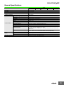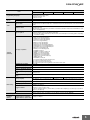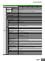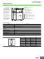
1
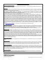
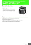
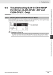
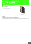
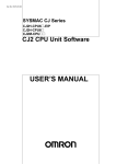
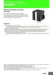
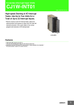
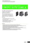
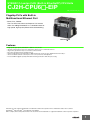
SYSMAC CJ-series CJ2H (Built-in EtherNet/IP) CPU Units
CJ2H-CPU6@-EIP
CSM_CJ2H-CPU-EIP_DS_E_9_2
Flagship PLCs with Built-in
Multifunctional Ethernet Port
• Small, Fast, Flexible:
The CJ2 CPU Units inherit and improve CJ1 features
while also adding EtherNet/IP as a standard feature for
high-speed, high-capacity Ethernet-based networking.
CJ2H-CPU6@-EIP
Features
•
•
•
•
•
•
•
High-speed, high-capacity EtherNet/IP is built into every model.
The CIP communications protocol is supported for direct access to multivendor devices.
Tag memory provided for easy access from host PCs and PTs.
Even more program memory and data memory.
Superior high-speed control performance: LOAD instructions execute in 16 ns, SINE instructions in 0.59 μs.
The more advanced motion control by the lower cost: Synchronous Unit Operation
Increased I/O throughput speed by Immediate refreshing instructions with direct processing.
Windows are either registered trademarks or trademarks of Microsoft Corporation in the United States and/or other countries.
EtherNet/IPTM and DeviceNetTM are trademarks of the ODVA.
Other company names and product names in this document are the trademarks or registered trademarks of their respective companies.
1
CJ2H-CPU6@-EIP
Ordering Information
International Standards
• The standards are abbreviated as follows: U: UL, U1: UL (Class I Division 2 Products for Hazardous Locations), C: CSA, UC: cULus,
UC1: cULus (Class I Division 2 Products for Hazardous Locations), CU: cUL, N: NK, L: Lloyd, and CE: EC Directives.
• Contact your OMRON representative for further details and applicable conditions for these standards.
CJ2H (Built-in EtherNet/IP) CPU Units
Current
consumption (A)
Specifications
Product
name
I/O capacity/Mountable
Units (Expansion Racks)
CJ2H
(Built-in
EtherNet/IP)
CPU Units
2,560 points / 40 Units
(3 Expansion Racks max.)
Program
capacity
Data memory capacity
LD
instruction
execution
time
Model
5V
400K steps
832K words
DM: 32K words
EM: 32K words × 25 banks
CJ2H-CPU68-EIP
250K steps
512K words
DM: 32K words
EM: 32K words × 15 banks
CJ2H-CPU67-EIP
150K steps
352K words
DM: 32K words
EM: 32K words × 10 banks
100K steps
160K words
DM: 32K words
EM: 32K words × 4 banks
CJ2H-CPU65-EIP
50K steps
160K words
DM: 32K words
EM: 32K words × 4 banks
CJ2H-CPU64-EIP
0.016 μs
0.82 *
Standards
24 V
−
CJ2H-CPU66-EIP
UC1, N, L,
CE
* Add 0.15 A per Adapter when using NT-AL001 RS-232C/RS-422A Adapters.
Add 0.04 A per Adapter when using CJ1W-CIF11 RS-422A Adapters.
Accessories
The following accessories come with CPU Unit:
Item
Specification
Battery
CJ1W-BAT01
End Cover
CJ1W-TER01 (necessary to be mounted at the right end of CPU Rack)
End Plate
PFP-M (2 pcs)
Serial Port (RS-232C) Connector
Connector set for serial port connection (D-SUB 9-pin male connector)
2
CJ2H-CPU6@-EIP
General Specifications
Item
CJ2HCPU64-EIP
CPU65-EIP
Enclosure
Mounted in a panel
Grounding
Less than 100 Ω
CPU Rack Dimensions
90 mm × 65 mm × 80 mm (H × D × W)
Weight *
280 g or less
Current Consumption
Use Environment
Battery
CPU66-EIP
CPU67-EIP
CPU68-EIP
5 VDC, 0.82 A
Ambient Operating Temperature
0 to 55°C
Ambient Operating Humidity
10% to 90% (with no condensation)
Atmosphere
Must be free from corrosive gases.
Ambient Storage Temperature
−20 to 70°C (excluding battery)
Altitude
2,000 m or less
Pollution Degree
2 or less: Conforms to JIS B3502 and IEC 61131-2.
Noise Immunity
2 kV on power supply line (Conforms to IEC 61000-4-4.)
Overvoltage Category
Category II: Conforms to JIS B3502 and IEC 61131-2.
EMC Immunity Level
Zone B
Vibration Resistance
Conforms to IEC60068-2-6.
5 to 8.4 Hz with 3.5-mm amplitude, 8.4 to 150 Hz
Acceleration of 9.8 m/s2 for 100 min in X, Y, and Z directions (10 sweeps of 10 min each =
100 min total)
Shock Resistance
Conforms to IEC60068-2-27.
147 m/s2, 3 times in X, Y, and Z directions (100 m/s2 for Relay Output Units)
Life
5 years at 25°C
Weight
Approx. 10 g
Model
CJ1W-BAT01
Applicable Standards
Conforms to cULus, NK, LR and EC Directives.
* Includes wight of end covers and battery.
3
CJ2H-CPU6@-EIP
Performance Specifications
CJ2H-
Items
CPU64-EIP
User Memory
50K steps
I/O Bits
2,560 bits
Processing
Speed
CPU65-EIP
100K steps
CPU66-EIP
150K steps
CPU67-EIP
250K steps
CPU68-EIP
400K steps
Overhead Processing Time
Normal Mode: 200 μs
(If tag data links are used with EtherNet/IP, add the following to the above time: 100 μs + Number of transferred
words × (0.33 μs or 0.87 μs *))
* When High-speed interrupt function is used
Execution Time
Basic Instructions: 0.016 μs min.;
Special Instructions: 0.048 μs min.
I/O Interrupts and
External Interrupts
Interrupt task startup time : 26 μs or 17 μs * (30 μs in unit Ver.1.0)
Return time to cyclic task : 11 μs or 8 μs * (15 μs in unit Ver.1.0)
* When High-speed interrupt function is used
Scheduled
Interrupts
Interrupt task startup time : 22 μs or 13 μs * (27 μs in unit Ver.1.0)
Return time to cyclic task : 11 μs or 8 μs * (15 μs in unit Ver.1.0)
* When High-speed interrupt function is used
Interrupts
Maximum Number of Connectable Units
Total per CPU Rack or Expansion Rack: 10 Units max.;
Total per PLC: 40 Units max.
Maximum Number of Expansion Racks
3 max.
I/O Area
2,560 bits (160 words): Words CIO 0000 to CIO 0159
Link Area
3,200 bits (200 words): Words CIO 1000 to CIO 1199
Synchronous Data Refresh Area 1,536 bits (96 words): Words CIO 1200 to CIO 1295
CIO Area
CPU Bus Unit Area
6,400 bits (400 words): Words CIO 1500 to CIO 1899
Special I/O Unit Area
15,360 bits (960 words): Words CIO 2000 to CIO 2959
DeviceNet Area
9,600 bits (600 words): Words CIO 3200 to CIO 3799
Internal I/O Area
3,200 bits (200 words): Words CIO 1300 to CIO 1499
37,504 bits (2,344 words): Words CIO 3800 to CIO 6143
Cannot be used for external I/O.
Work Area
8,192 bits (512 words): Words W000 to W511
Cannot be used for external I/O.
Holding Area
8,192 bits (512 words): Words H000 to H511
Bits in this area maintain their ON/OFF status when PLC is turned OFF or operating mode is changed.
Words H512 to H1535: These words can be used only for function blocks. They can be used only for function
block instances (i.e., they are allocated only for internal variables in function blocks).
Auxiliary Area
Read-only: 31,744 bits (1,984 words)
• 7,168 bits (448 words): Words A0 to A447
• 24,576 bits (1,536 words): Words A10000 to A11535 *
Read/write: 16,384 bits (1,024 words) in words A448 to A1471 *
* A960 to A1471 and A10000 to A11535 cannot be accessed by CPU Bus Units, Special I/O Units, PTs, and
Support Software that do not specifically support the CJ2 CPU Units.
Temporary Area
16 bits: TR0 to TR15
Timer Area
4,096 timer numbers (T0000 to T4095 (separate from counters))
Counter Area
4,096 counter numbers (C0000 to C4095 (separate from timers))
DM Area
32k words *
DM Area words for Special I/O Units: D20000 to D29599 (100 words × 96 Units)
DM Area words for CPU Bus Units: D30000 to D31599 (100 words × 16 Units)
* Bits in the EM Area can be addressed either by bit or by word. These bits cannot be addressed by CPU Bus
Units, Special I/O Units, PTs, and Support Software that do not specifically support the CJ2 CPU Units.
32k words/bank × 25 banks max.: E00_00000 to E18_32767 max. *1 *2
*1. Bits in the EM Area can be addressed either by bit or by word. These bits cannot be addressed by CPU
Bus Units, Special I/O Units, PTs, and Support Software that do not specifically support the CJ2 CPU
Units.
*2. EM banks D to 18 cannot be accessed by CPU Bus Units, Special I/O Units, PTs, and Support Software
that do not specifically support the CJ2 CPU Units.
*3. Force-set/reset to the EM Area is enabled by specifying a start bank in parameter settings. (unit version
1.2 or higher)
EM Area
Force-S/R
Enabled
Banks
32K words × 4
banks
32K words × 4
banks
32K words × 10
banks
32K words × 15
banks
32K words × 25
banks
When EM force-S/R
function is used *3
Bank 0 to 3
Bank 0 to 3
Bank 0 to 9
Bank 0 to E
Bank 0 to 18
When automatic
address allocation
is specified
Bank 3
Bank 3
Bank 6 to 9
Bank 7 to E
Bank 11 to 18
Index Registers
IR0 to IR15
These are special registers for storing PLC memory addresses for indirect addressing. (Index Registers can
be set so that they are unique in each task or so that they are shared by all tasks.)
Cyclic Task Flag Area
128 flags
Memory Card
128 MB, 256 MB, or 512 MB
Operating Modes
PROGRAM Mode: Programs are not executed. Preparations can be executed prior to program execution in
this mode.
MONITOR Mode: Programs are executed, and some operations, such as online editing, and changes to
present values in I/O memory, are enabled in this mode.
RUN Mode:
Programs are executed. This is the normal operating mode.
Execution Mode
Normal Mode
4
CJ2H-CPU6@-EIP
Items
Programming Languages
Function
Blocks
CJ2HCPU64-EIP
CPU65-EIP
CPU66-EIP
CPU67-EIP
CPU68-EIP
Ladder Logic (LD),
Sequential Function Charts (SFC),
Structured Text (ST), and
Instruction Lists (IL)
Maximum number of definitions
2,048
Maximum number of instances
2,048
Type of Tasks
Cyclic tasks
Interrupt tasks (Power OFF interrupt tasks, scheduled interrupt tasks, I/O interrupt tasks, and external interrupt
tasks)
Number of Tasks
Cyclic tasks: 128
Interrupt tasks: 256
(Interrupt tasks can be defined as cyclic tasks to create extra cyclic tasks. Therefore, the total number of cyclic
tasks is actually 384 max.)
Type of Symbols
• Local symbols: Can be used only within a single task in the PLC.
• Global symbols: Can be used in all tasks in the PLC.
• Network symbols (tags): I/O memory in the CPU Unit can be externally accessed using symbols, depending
on parameter settings.
Tasks
Data Type of Symbols
• BOOL (bit)
• UINT (one-word unsigned binary)
• UDINT (two-word unsigned binary)
• ULINT (four-word unsigned binary)
• INT (one-word signed binary)
• DINT (two-word signed binary)
• LINT (four-word signed binary)
• UINT BCD (one-word unsigned BCD) *1
• UDINT BCD (two-word unsigned BCD) *1
• ULINT BCD (four-word unsigned BCD) *1
• REAL (two-word floating-point)
• LREAL (four-word floating-point)
• CHANNEL (word) *1
• NUMBER (constant or number) *1
• WORD (one-word hexadecimal)
• DWORD (two-word hexadecimal)
• LWORD (four-word hexadecimal)
• STRING (1 to 255 ASCII characters)
• TIMER (timer) *2
• COUNTER (counter) *2
• User defined data types (data structures) *3
*1. Cannot be used in Function blocks
*2. Can be used only in Function blocks
*3. Supported only when CX-Programmer version 9.0 or later is used
Maximum Size of Symbol
32k words
Symbols
(Variables)
Array Symbols (Array Variables) One-dimensional arrays
Number of Array Elements
32,000 elements max.
Number of Registrable Network
Symbols (Tags)
20,000 max.
Length of Network Symbol (Tag)
Name
255 bytes max.
Encoding of Network Symbols
(Tags)
UTF-8
8,000 words
Data Tracing
32,000 words
(The EM Area can be specified from the CX-Programmer to use up to 32K words multiplied by the number of
banks supported by the CPU Unit model.)
Number of Samplings
Bits = 31, one-word data =16, two-word data = 8, four-word data = 4
Sampling Cycle
1 to 2,550 ms (Unit: 1 ms)
Trigger Conditions
ON/OFF of specified bit
Data comparison of specified word
Data size: 1 word, 2 words, 4 words
Comparison Method: Equals (=), Greater Than (>), Greater Than or Equals (≥), Less Than (<), Less Than or
Equals (≤), Not Equal (≠)
Delay Value
−32,768 to +32,767 ms
Memory Card (128, 256, or 512 Mbytes) (Use the Memory Cards provided by OMRON.)
EM file memory (Part of the EM Area can be converted for use as file memory.)
File Memory
Source/
Comment
Memory
16,000 words
Memory Capacity
Program sources, comments,
program indexes, symbol tables
Capacity: 3.5 Mbytes
5
CJ2H-CPU6@-EIP
CJ2H-
Item
Logical Ports for
Communications
CIP
Communications
Specification
CPU64-EIP
CPU65-EIP
CPU66-EIP
8 ports (Used for SEND, RECV, CMND, PMCR, TXDU, and RXDU instructions.)
Extended Logical
Ports
64 ports (Used for SEND2, RECV2, CMND2, and PMCR2 instructions.)
Class 3 (Connection
Type)
Number of connections: 64
UCMM (Nonconnection Type)
Maximum number of clients that can communicate at the same time: 32
Maximum number of servers that can communicate at the same time: 40
Peripheral (USB) Port
Baud Rate
Transmission Distance
Serial Port
12 Mbps max.
5 m max.
Interface: Conforms to EIA RS-232C.
Half-duplex
Synchronization Method
Start-stop
Baud Rate
0.3, 0.6, 1.2, 2.4, 4.8, 9.6, 19.2, 38.4, 57.6, or 115.2 (kbps)
Transmission Distance
Transmission Specifications
EtherNet/IP Port
Communications Specifications
CPU68-EIP
USB 2.0-compliant B-type connector
Communications Method
Communications
CPU67-EIP
Logical Ports
15 m max.
−
Media Access Method
CSMA/CD
Modulation
Baseband
Transmission Paths
Star
Baud Rate
100 Mbps (100Base-TX)
Transmission Media
Shielded twisted-pair (STP) cable; Categories: 5, 5e
Transmission Distance
100 m (between hub and node)
Number of Cascade Connections
No restrictions if switching hub is used.
CIP Communications: Tag Data Links
−
Number of Connections
256
Packet Interval (Refresh period)
0.5 to 10,000 ms (Unit: 0.5 ms)
Can be set for each connection. (Data will be refreshed at the set interval, regardless of the number
of nodes.)
Maximum allowed communications
bandwidth per Unit
6,000 to 12,000 pps *1 *2
Number of Registerable Tag
256
Type of Tags
CIO, DM, EM, HR, WR, and Network symboles
Number of Tags per Connection
8 (Seven tags if PLC status is included in the segment.)
Maximum Link Data Size per Node
184,832 words
Maximum Data Size per Connection
252 or 722 words *3
(Data is synchronized within each connection.)
Number of Registrable Tag Set
256 (1 connection = 1 segment)
Maximum Tag Set Size
722 words (One word is used when PLC status is included in the segment.)
Maximum Number of Tags
Refreshable in a Single Cycle of
CPU Unit *4
Output/send (CPU Unit to EtherNet/IP): 256
Input/receive (EtherNet/IP to CPU Unit): 256
Data Size Refreshable in a Single
Cycle of CPU Unit *4
Output/send (CPU to EtherNet/IP): 6,432 words
Input/receive (EtherNet/IP to CPU): 6,432 words
Change of Tag Data Link Parameter
Settings during Operation
OK *5
Multi-cast Packet Filter *6
OK
CIP Communications: Explicit
Messages
−
Class 3 (Connection Type)
Number of connections: 128
UCMM (Non-connection Type)
Maximum number of clients that can communicate at the same time: 32
Maximum number of servers that can communicate at the same time: 32
CIP Routing
OK
(CIP routing is enabled for the following remote Units: CJ1W-EIP21, CJ2H-CPU6@-EIP, CJ2M-CPU3@,
and CS1W-EIP21.)
FINS Communications
FINS/UDP
FINS/TCP
−
OK
16 connections max.
EtherNet/IP Conformance Test
Conforms to A5.
EtherNet/IP Interface
10Base-T/100Base-TX
Auto Negotiation/Fixed Setting
6
CJ2H-CPU6@-EIP
*1. "Packets per second" is the number of communications packets that can be processed per second.
*2. When using the EtherNet/IP Unit with version 3.0 or later. When using the EtherNet/IP Unit with version 2.1 or earlier, the maximum allowed
communications bandwidth per Unit is 6,000 pps. When using the EtherNet/IP Unit with version 3.0 or later, the Network Configurator with
version 3.57 or higher is required.
*3. Large Forward Open (CIP optional specification) must be supported in order for 505 to 1,444 bytes to be used as the data size. Application is
supported between CS/CJ-series PLCs. When connecting to devices from other manufacturers, make sure that the devices support the Large
Forward Open specification.
*4. If the maximum number is exceeded, refreshing will require more than one CPU Unit cycle.
*5. When changing parameters, however, the EtherNet/IP port where the change is made will be restarted. In addition, a timeout will temporarily
occur at the other node that was communicating with that port, and it will then recover automatically.
*6. The EtherNet/IP port supports an IGMP client, so unnecessary multicast packets are filtered by using a switching hub that supports IGMP
snooping.
Function Specifications
Functions
Cycle Time
Management
Description
Minimum Cycle Time
A minimum cycle time can be set.
(0.2 to 32,000 ms; Unit: 0.1 ms)
The minimum cycle time setting can be changed in MONITOR mode. (Unit version 1.1
or higher)
Cycle Time Monitoring
The cycle time is monitored.
(0.01 to 40,000 ms; Unit: 0.01 ms)
Background Processing
Instructions with long execution times can be executed over multiple cycles to prevent
fluctuations in the cycle time.
Basic I/O
Units, Special
I/O Units, and
CPU Bus
Units
Basic I/O
Units
Unit (I/O)
Management
Special I/O
Units and
CPU Bus
Units
Configuration
Management
I/O
Refreshing
Cyclic Refreshing
Cyclic refreshing of Basic I/O Units, Special I/O Units, and CPU Bus Units
Immediate Refreshing
I/O refreshing by immediate refreshing instructions
Refreshing by IORF
I/O refreshing by IORF instruction
Unit Recognition at Startup
The number of units recognized when the power is turned ON is displayed.
Input Response Time Setting
The input response times can be set for Basic I/O Units. The response time can be
increased to reduce the effects of chattering and noise at input contacts. The response
time can be decreased to enable detecting shorter input pulses.
Load OFF Function
All of the outputs on Basic I/O Units can be turned OFF when an error occurs in RUN or
MONITOR mode.
Basic I/O Unit Status Monitoring
Alarm information can be read from Basic I/O Units and the number of Units recognized
can be read.
Unit Restart Bits to Restart Units
A Special I/O Unit or CPU Bus Unit can be restarted.
Synchronous Unit Operation
The start of processing for all the specified Units can be synchronized at a fixed interval.
Maximum number of Units: 10 Units
(Only Units that support Synchronous Operation Mode can be used.)
Synchronous operation cycle: 0.5 to 10 ms (default: 2 ms)
Maximum number of words for synchronous data refreshing: 96 words (total of all Units)
Automatic I/O Allocation at Startup
I/O words can be automatically allocated to the Basic I/O Units that are connected in the
PLC to start operation automatically without registering Units into I/O tables.
I/O Table Creation
The current unit configuration can be registered in I/O tables to prevent it from being
changed, to reserve words, and to set words.
Rack/Slot First Word Settings
The first words allocated to a Units on the Racks can be set.
The status of I/O memory can be held when the operating mode is changed or power is
Holding I/O Memory when Changing Operating Modes turned ON. The forced-set/reset status can be held when the operating mode is changed
or power is turned ON.
Memory
Management
Memory
Cards
File Memory
Files (such as program files, data files, and symbol table files) can be stored in Memory
Card, EM File Memory, or Comment Memory.
Built-in Flash Memory
The user program and Parameter Area can be backed up to an internal flash memory
when they are transferred to the CPU Unit.
EM File Function
Parts of the EM Area can be treated as file memory.
Storing Comments
I/O comments can be stored as symbol table files in a Memory Card, EM file memory,
or comment memory.
EM Configuration
EM Area can be set as trace memory or EM file memory.
Automatic File Transfer at Startup
A program file and parameter files can be read from a Memory Card when the power is
turned ON.
Program Replacement during PLC Operation
The whole user program can be read from a Memory Card to CPU Unit during operation.
Function for Reading and Writing Data from a Memory
Card
Data in I/O memory in the CPU Unit can be written to a Memory Card in CSV/TXT format.
Data in CSV/TXT format in the Memory Card can be read to I/O memory in the CPU Unit.
7
CJ2H-CPU6@-EIP
Function
Peripheral (USB)
Port
Peripheral Bus
Serial Port
Bus for communications with various kinds of Support Software running on a personal
computer. High-speed communications are supported.
−
Host Link (SYSWAY) Communications
Host Link commands or FINS commands placed between Host Link headers and terminators
can be sent from a host computer or PT to read/write I/O memory, read/control the operating
mode, and perform other operations for PLC.
No-protocol Communications
I/O instructions for communications ports (such as TXD/RXD instructions) can be used for
data transfer with peripheral devices such as bar code readers and printers.
NT Link Communications
I/O memory in the PLC can be allocated and directly linked to various PT functions, including
status control areas, status notification areas, touch switches, lamps, memory tables, and
other objects.
Peripheral Bus
Bus for communications with various kinds of Support Software running on a personal
computer. High-speed communications are supported.
Serial Gateway
This gateway enables receiving and automatically converting FINS to the CompoWay/F.
EtherNet/IP Port
CIP
Tag Data Links
Communications
Message Communications
Service
FINS
Communications Message Communications
Service
Interrupt
Description
−
Communications
100Base-TX/10Base-T
Protocols: TCP/IP, UDP, ARP, ICMP (ping only), BOOTP
Applications: FINS, CIP, SNTP, DNS (Client), FTP (Server)
Programless cyclic data exchanges with the devices on the EtherNet/IP network.
Any CIP commands can be received from the devices on the EtherNet/IP network.
Any FINS commands can be transferred with the devices on the EtherNet/IP network.
Scheduled Interrupts
Tasks can be executed at a specified interval (minimum of 0.2 ms or 0.1 ms *, Unit: 0.1 ms).
* When High-speed interrupt function is used.
Power OFF Interrupts
A task can be executed when CPU Unit's power turns OFF.
I/O Interrupt Tasks
A task can be executed when an input signal is input to an Interrupt Input Unit.
External Interrupt Tasks
A task can be executed when interrupts are requested from a Special I/O Unit or a CPU Bus Unit.
High-speed Interrupt Function
Improves performance for executing interrupt tasks with certain restrictions.
(Unit version 1.1 or later.)
Clock Function
Clock data is stored in memory.
Accuracy (Accuracy depends on the temperature.)
Ambient temperature of 55°C: −3.5 to +0.5 min error per month
Ambient temperature of 25°C: −1.5 to +1.5 min error per month
Ambient temperature of 0°C: −3 to +1 min error per month
Operation Start Time Storage
The time when operating mode was last changed to RUN mode or MONITOR mode is stored.
Operation Stop Time Storage
The last time a fatal error occurred or the last time the operating mode was changed to
PROGRAM mode is stored.
Startup Time Storage
The time when the power was turned ON is stored.
Power Interruption Time Storage
The time when the power is turned OFF is stored.
Total Power ON Time Calculation
The total time that the PLC has been ON is stored in increments of 10 hours.
Power ON Clock Data Storage
A history of the times when the power was turned ON is stored.
User Program Overwritten Time Storage
The time that the user program was last overwritten is stored.
Parameter Date Storage
The time when the Parameter Area was overwritten is stored.
Memory Protection
Holding Area data, DM Area data, EM Area data, Counter Completion Flags, and counter
present values are held even when power is turned OFF. CIO Area, Work Area, some Auxiliary
Area data, and Timer Completion Flags, timer present values, index registers, and data
registers can be protected by turning ON the IOM Hold Bit in the Auxiliary Area, and by also
setting the IOM Hold Bit to “Hold” in the PLC Setup.
Clock
Power
Supply
Management Power OFF Detection Time Setting
The detection time for power interruptions can be set.
AC power supply: 10 to 25 ms (variable)
DC power supply: 2 to 5 ms (CJ1W-PD022) or 2 to 20 ms (CJ1W-PD025)
Power OFF Detection Delay Time
The detection of power interruptions can be delayed: 0 to 10 ms
(Not supported by the CJ1W-PD022.)
Number of Power Interruptions Counter
The number of times power has been interrupted is counted.
Function Blocks
Standard programming can be encapsulated as function blocks.
Languages in Function Block Definitions
Ladder programming or structured text
Online Editing
The program can be changed during operation (in MONITOR or PROGRAM mode), except for
block programming areas.
Force-Set/Reset
Specified bits can be set or reset.
Force-set/reset to the EM Area is enabled by specifying a start bank in parameter setting.
(unit version 1.2 or higher)
Differentiate Monitoring
ON/OFF changes in specified bits can be monitored.
Data Tracing
The specified I/O memory data can be stored in the trace memory in the CPU Unit. The
triggers can be set.
• The trace data can be uploaded during data tracing using CX-Programmer, which enables
continuously logging the data by constantly uploading the trace data (trace data uploading
during tracing).
• Data tracing can be automatically started when operation is started (i.e., when the operating
mode is changed from PROGRAM mode to MONITOR or RUN mode).
Debugging
Storing Location of Error when an Error Occurs
The location and task number where execution stopped for a program error is recorded.
Program Check
The programs can be checked for items such as no END instruction and FALS/FAL errors at startup.
8
CJ2H-CPU6@-EIP
Function
Description
Error Log
A function is provided to store predefined error codes in CPU Unit, error information, and time
at which the error occurred.
CPU Error Detection
CPU Unit WDT errors are detected.
User-defined Failure Diagnosis
Errors can be generated for user-specified conditions: Non-fatal errors (FAL) and fatal errors
(FALS).
Program section time diagnosis and program section logic diagnosis are supported (FPD
instruction).
Load OFF Function
This function turns OFF all outputs from Output Units when an error occurs.
RUN Output
The RUN output from the CJ1W-PA205R turns ON while CPU Unit is in RUN mode or
MONITOR mode.
Basic I/O Load Short-circuit Detection
This function provides alarm information from Basic I/O Units that have load short-circuit
protection.
Failure Point Detection
The time and logic of an instruction block can be analyzes using the FPD instruction.
CPU Standby Detection
This function indicates when the CPU Unit is on standby because all Special I/O Units and
CPU Bus Units have not been recognized at the startup in RUN or MONITOR mode.
System FAL Error Detection This function generates a non-fatal (FAL) error when the user-defined conditions are met in
(User-defined non-fatal error) program.
Duplicate Refreshing Error
Detection
This function detects an error when an immediate refreshing Instruction in an interrupt task is
competing with I/O refreshing of a cyclic task.
Basic I/O Unit Error Detection This function detects the errors in Basic I/O Units.
Non-fatal Error
Detection
Selfdiagnosis
and
Restoration
Backup Memory Error
Detection
This function detects errors in the memory backup of the user programs and parameter area
(backup memory).
PLC Setup Error Detection
This function detects setting errors in the PLC Setup.
CPU Bus Unit Error Detection
This function detects an error when there is an error in data exchange between the CPU Unit
and a CPU Bus Unit.
Special I/O Unit Error
Detection
This function detects an error when there is an error in data exchange between the CPU Unit
and a Special I/O Unit.
Tag Memory Error Detection
This function detects errors in tag memory.
Battery Error Detection
This function detects an error when a battery is not connected to the CPU Unit or when the
battery voltage drops.
CPU Bus Unit Setting Error
Detection
This function detects an error when the model of a CPU Bus Unit in the registered I/O tables
does not agree with the model that is actually mounted in the PLC.
Special I/O Unit Setting Error
Detection
This function detects an error when the model of a Special I/O Unit in the registered I/O tables
does not agree with the model of Unit that is actually mounted.
Memory Error Detection
This function detects errors that occur in memory of the CPU Unit.
I/O Bus Error Detection
This function detects when an error occurs in data transfers between the Units mounted in
Rack slots and the CPU Unit and detects when the End Cover is not connected to the CPU
Rack or an Expansion Rack.
Unit/Rack Number
Duplication Error
This function detects an error when the same unit number is set for two or more Units, the
same word is allocated to two or more Basic I/O Units, or the same rack number is set for two
or more Racks.
Too Many I/O Points Error
Detection
This function detects an error when the total number of I/O points set in the I/O tables or the
number of Units per Rack exceeds the specified range.
I/O Setting Error Detection
This function detects an error when the number of Units in the registered I/O tables does not
agree with the actual number of Units that is mounted, or an Interrupt Unit has been connected
in the wrong position, i.e., not in slot 0 to 3.
Program Error Detection
Fatal Error
Detection
Fatal Error
Detection
(Continued from
previous page)
This function detects errors in programs.
Instruction Processing
Error Detection
This function detects an error when the given data value is invalid when executing an
instruction, or execution of instruction between tasks was attempted.
Indirect DM/EM BCD
Error Detection
This function detects an error when an indirect DM/EM address in BCD mode is not BCD.
Illegal Area Access Error
Detection
This function detects an error when an attempt is made to access an illegal area with an
instruction operand.
No END Error Detection
This function detects an error when there is no END instruction at the end of the program.
Task Error Detection
This function detects an error when there are no tasks that can be executed in a cycle, there
is no program for a task, or the execution condition for an interrupt task was met but there is
no interrupt task with the specified number.
Differentiation Overflow
Error Detection
This function detects an error when too many differentiated instructions are entered or deleted
during online editing (131,072 times or more).
Invalid Instruction Error
Detection
This function detects an error when an attempt is made to execute an instruction that is not
defined in the system.
User Program Area
Overflow Error Detection
This function detects an error when instruction data is stored after the last address in user
program area.
Cycle Time Exceeded Error
Detection
This function monitors the cycle time (10 to 40,000 ms) and stops the operation when the set
value is exceeded.
System FALS Error Detection
(User-defined Fatal Error)
This function generates a fatal (FALS) error when the user-defined conditions are met in
program.
Version Error Detection
This function detects an error when a user program includes a function that is not supported
by the current unit version.
Memory Card Transfer Error
Detection
This function detects an error when the automatic file transfer from Memory Card fails at
startup.
Memory Self-restoration Function
This function performs a parity check on the user program area and self-restoration data.
9
CJ2H-CPU6@-EIP
Function
Maintenance
Description
Simple Backup Function
This function collectively backs up the data in CPU Unit (user programs, parameters, and I/O
memory) and internal backup data in the I/O Units.
Unsolicited Communications
A function that allows the PLC to use Network Communications Instruction to send required
FINS commands to a computer connected via a Host Link
Remote Programming and Monitoring
Host Link communications can be used for remote programming and remote monitoring through a Controller Link,
Ethernet, DeviceNet, or SYSMAC LINK Network. Communications across network layers can be performed.
Controller Link or Ethernet: 8 layers
DeviceNet or SYSMAC LINK: 3 layers
Automatic Online Connection via
Network
Security
Direct Serial
Connection
This function enables automatically connecting to the PLC online when the CX-Programmer
is directly connected by a serial connection (peripheral (USB) port or serial port).
Via Networks This function enables connecting the CX-Programmer online to a PLC that is connected via an EtherNet/IP network.
Read Protection using Password
This function protects reading and displaying programs and tasks using passwords.
Write protection: Set using the DIP switch.
Read protection: Set a password using the CX-Programmer.
FINS Write Protection
This function prohibits writing by using FINS commands sent over the network.
Unit Name Function
This function allows the users to give any names to the Units. Names are verified at online
connection to prevent wrong connection
Hardware ID Using Lot Numbers
This function sets operation protection by identifying hardware using the user programs
according to lot numbers stored in the Auxiliary Area.
Unit Versions
Units
Models
CJ2H CPU Units
CJ2H-CPU6@-EIP
Unit version
CPU: Unit version 1.4
EIP: Unit version 2.@ / Unit version 3.@
CPU: Unit version 1.3
EIP: Unit version 2.0
CPU: Unit version 1.2
EIP: Unit version 2.0
CPU: Unit version 1.1
EIP: Unit version 2.0
CPU: Unit version 1.0
EIP: Unit version 2.0
Function Support by Unit Version
Unit Version 1.4 or Later
CX-Programmer version 9.3 or higher must be used to enable using the functions added for unit version 1.4.
Unit
CJ2H CPU Unit
Model
CJ2H-CPU6@-EIP
Unit version
Unit version 1.4 or higher
Unit version 1.3 or earlier
Supported.
Not supported.
Item
Synchronous unit operation function
Position Control Units with EtherCAT interface CJ1W-NC@82 work for synchronous unit operation.
Unit Version 1.3 or Later
CX-Programmer version 9.1 or higher must be used to enable using the functions added for unit version 1.3.
Unit
CJ2H CPU Unit
Model
CJ2H-CPU6@-EIP
Unit version
Unit version 1.3 or later
Unit version 1.2 or earlier
CJ1W-NC281/NC481/NC881 Position Control Units: PCU
HIGH-SPEED POSITIONING (NCDMV(218))
Supported.
Not supported.
CJ1W-NC281/NC481/NC881 Position Control Units: PCU
POSITIONING TRIGGER (NCDTR(219))
Supported.
Not supported.
Item
Special instructions for certain
Special I/O Units
New special instructions
SIGNED AREA RANGE COMPARE: ZCPS(088)
Supported.
Not supported.
DOUBLE SIGNED AREA RANGE COMPARE: ZCPSL(116)
Supported.
Not supported.
Unit Version 1.2 or Later
CX-Programmer version 8.3 or higher must be used to enable using the functions added for unit version 1.2.
Unit
CJ2H CPU Unit
Model
CJ2H-CPU6@-EIP
Unit version
Unit version 1.2 or higher
Unit version 1.1 or earlier
Supported.
Not supported.
Item
EM force-set/reset function
Note: User programs that use functions of CJ2H CPU Units with unit version 1.2 or later cannot be used with CJ2H CPU Units with unit version
1.1 or earlier. If an attempt is made to transfer a program that uses any of these functions from the CX-Programmer to a CPU Unit with unit
version 1.1 or earlier , an error will be displayed and it will not be possible to download to the CPU Unit.
10
CJ2H-CPU6@-EIP
Unit Version 1.1 or Later
CX-Programmer version 8.1 or higher must be used to enable using the functions added for unit version 1.1.
Unit
CJ2H CPU Unit
Model
CJ2H-CPU6@-EIP
Unit version
Unit version 1.1 or higher
Unit version 1.0
High-speed interrupt function
Decreased overhead time for interrupt tasks
Minimum interval setting of 0.1 ms for Scheduled Interrupt Task
Supported.
Not supported.
Item
Changing the minimum cycle time setting in MONITOR mode
Supported.
Not supported.
Synchronous unit operation function
Position Control Units (High-speed type) CJ1W-NC@@4 work for synchronous unit operation.
Supported.
Not supported.
Addition of Immediate refreshing instruction only for specific Special I/O Units and CPU Bus Units
For CJ1W-AD042 : Analog Input Direct Convert AIDC (216)
For CJ1W-DA042V : Analog Output Direct Convert AODC (217)
For CJ1W-SCU22/32/42 :
Direct Receive Via Serial Communications Unit DRXDU (261)
Direct Transmit Via Serial Communications Unit DTXDU (262)
Supported.
Not supported.
Note: User programs that use functions of CJ2H CPU Units with unit version 1.1 or later cannot be used with CJ2H CPU Units with unit version
1.0. If an attempt is made to transfer a program that uses any of these functions from the CX-Programmer to a CPU Unit with unit version
1.0, an error will be displayed and it will not be possible to download to the CPU Unit. If a program file (extension: .OBJ) that uses any of
these functions is transferred to a CPU Unit with unit version 1.0, a program error will occur when operation starts or when the function starts
and operation of the CPU Unit will stop.
Unit Versions and Programming Devices
The following tables show the relationship between unit versions and CX-Programmer versions.
Unit Versions and Programming Devices
Required Programming Device
CPU Unit
CX-Programmer
Functions
Ver. 7.1 or
lower
Ver.8.0
Ver.8.1/
Ver.8.2
Ver. 8.3
Ver. 9.1/
Ver.9.2
Ver. 9.3 or
higher
CJ2H-CPU6@-EIP
Unit version 1.4
Functions
added for unit
version 1.4
Using new functions
−
−
−
−
−
OK
Not using new
functions
−
OK *1
OK *1
OK
OK
OK
CJ2H-CPU6@-EIP
Unit version 1.3
Functions
added for unit
version 1.3
Using new functions
−
−
−
−
OK
OK
Not using new
functions
−
OK *1
OK *1
OK
OK
OK
CJ2H-CPU6@-EIP
Unit version 1.2
Functions
added for unit
version 1.2
Using new functions
−
−
−
OK
OK
OK
Not using new
functions
−
OK *1
OK *1
OK
OK
OK
CJ2H-CPU6@-EIP
Unit version 1.1
Functions
added for unit
version 1.1
Using new functions
−
−
OK *2
OK
OK
OK
Not using new
functions
−
OK *1
OK
OK
OK
OK
CJ2H-CPU6@-EIP
Unit version 1.0
Functions for unit version 1.0
−
OK
OK
OK
OK
OK
Programming
Console
− *3
*1. It is not necessary to upgrade the version of the CX-Programmer if functionality that was enhanced for the upgrade of the CPU Unit will not be
used.
*2. CX-Programmer version 8.2 or higher is required to use the added functions in CJ2H CPU Units (CJ2H-CPU6@-EIP) with unit version 1.1.
However only High-speed interrupt function and Changing the minimum cycle time setting in MONITOR mode are supported in CXProgrammer version 8.02.
*3. A Programming Console cannot be used with a CJ2H CPU Unit.
Device Type Setting
The unit version does not affect the setting made for the device type on the CX-Programmer. Select the device type as shown in the following table
regardless of the unit version of the CPU Unit.
Series
CJ Series
CPU Unit group
CJ2H CPU Units
Device type setting on
CX-Programmer Ver. 8.0 or higher
CPU Unit model
CJ2H-CPU6@-EIP
CJ2H
11
CJ2H-CPU6@-EIP
External Interface
A CJ2H CPU Unit (CJ2H-CPU6@-EIP) provides three communications ports for external interfaces: a peripheral (USB) port, a serial port and an
EtherNet/IP port.
LED Indicators
Battery Compartment
DIP Switch
(inside the battery compartment)
Simple Backup/Memory Card
Power Supply Switch
Used to back up Memory
Card data or turn OFF the
power when removing the
Memory Card.
Also, press the Memory Card
Power Supply Switch to
perform an easy backup
operation.
Memory Card Indicators
Indicates the Memory Card status
(access and power supply).
Peripheral (USB) Port
Connected to Programming Devices,
such as the CX-Programmer
Serial Port
Connected to Programming Devices, Host
Computers, general-purpose external devices,
Programmable Terminals, and other devices.
Memory Card Connector
Connects the Memory Card
to the CPU Unit.
EtherNet/IP Port
Connected to the information management
system such as Host Computer
Memory Card Eject Button
Press the eject button to
remove the Memory Card
from the CPU Unit.
Peripheral (USB) Port
Item
Specification
Baud Rate
12 Mbps max.
Transmission Distance
5 m max.
Interface
USB 2.0-compliant B-type connector
Protocol
Peripheral Bus
Serial Port
Item
Specification
Communications method
Half duplex
Synchronization
Start-stop
Baud rate
0.3/0.6/1.2/2.4/4.8/9.6/19.2/38.4/57.6/115.2 kbps *
Transmission distance
15 m max.
Interface
EIA RS-232C
Protocol
Host Link, NT Link, 1:N, No-protocol, or Peripheral Bus
* Baud rates for the RS-232C are specified only up to 19.2 kbps. The CJ Series supports serial communications from 38.4 kbps to 115.2 kbps,
but some computers cannot support these speeds. Lower the baud rate if necessary.
Pin No.
1
6
9
5
Signal
Name
Protection earth
Direction
−
1
FG
2
SD (TXD)
Send data
Output
3
RD (RXD)
Receive data
Input
4
RS (RTS)
Request to send
Output
5
CS (CTS)
Clear to send
Input
6
5V
Power supply
−
7
DR (DSR)
Data set ready
Input
8
ER (DTR)
Data terminal ready
Output
9
SG (0 V)
Signal ground
−
Connector hood
FG
Protection earth
−
Note: Do not use the 5-V power from pin 6 of the RS-232C port for anything but CJ1W-CIF11 RS-422A Conversion Adapter, NT-AL001 RS-232C/
RS-422A Conversion Adapter and NV3W-M@20L Programmable Terminal. The external device or the CPU Unit may be damaged.
12
CJ2H-CPU6@-EIP
EtherNet/IP Port
Item
Specification
Media Access Method
CSMA/CD
Modulation
Baseband
Transmission Paths
Star
Baud Rate
100 Mbps (100Base-TX)
Transmission Media
Shielded twisted-pair (STP) cable; Categories: 5, 5e
Transmission Distance
100 m (between hub and node)
Number of Cascade Connections
No restrictions if switching hub is used.
Communications
CIP Communications (tag data links, Explicit Messages).
FINS communications
Dimensions
(Unit: mm)
CJ2H CPU Unit
CJ2H-CPU6@-EIP
66.2
2.7
90
2.7
79.8
65
74.5
13
CJ2H-CPU6@-EIP
Related Manuals
Cat. No.
W472
Model
CJ2H-CPU6@-EIP
CJ2H-CPU6@
CJ2M-CPU@@
Manual
CJ-series CJ2 CPU Unit
Hardware User’s
Manual
Application
Description
Hardware specifications for CJ2
CPU Units
Describes the following for CJ2 CPU Units:
• Overview and features
• Basic system configuration
• Part nomenclature and functions
• Mounting and setting procedure
• Remedies for errors
• Also refer to the Software User’s Manual (W473).
W473
CJ2H-CPU6@-EIP
CJ2H-CPU6@
CJ2M-CPU@@
CJ-series CJ2 CPU Unit
Software User’s Manual
Software specifications for CJ2
CPU Units
Describes the following for CJ2 CPU Units:
• CPU Unit operation
• Internal memory
• Programming
• Settings
• Functions built into the CPU Unit
Also refer to the Hardware User’s Manual (W472)
W474
CJ2H-CPU6@-EIP
CJ2H-CPU6@
CJ2M-CPU3@
CJ2M-CPU1@
CS1G/H-CPU@@H
CS1G/H-CPU@@-V1
CJ1G/H-CPU@@H
CJ1G-CPU@@
CJ1M-CPU@@
NSJ@-@@@@(@)-@@@
CS/CJ/NSJ-series
Instructions Reference
Manual
Information on instructions
Describes each programming instruction in detail.
Also refer to the Software User’s Manual (W473) when you
do programming.
W342
CJ2H-CPU6@-EIP
CJ2H-CPU6@
CJ2M-CPU@@
CS1G/H-CPU@@H
CS1G/H-CPU@@-V1
CS1D-CPU@@H
CS1D-CPU@@S
CS1W-SCU@@-V1
CS1W-SCB@@-V1
CJ1H-CPU@@H-R
CJ1G/H-CPU@@H
CJ1G-CPU@@P
CJ1M-CPU@@
CJ1G-CPU@@
CJ1W-SCU@@-V1
CP1H-X@@@@-@
CP1H-XA@@@@-@
CP1H-Y@@@@-@
NSJ@-@@@@(@)-@@@
CS/CJ/CP/NSJ-series
Communications
Command Reference
Manual
Information on communications
for CS/CJ/CP-series CPU Units
and NSJ-series Controllers
Describes C-mode commands and FINS commands
Refer to this manual for a detailed description of commands
for communications with the CPU Unit using C mode
commands or FINS commands.
Note: This manual describes the communications
commands that are addressed to CPU Units. The
communications path that is used is not relevant and
can include any of the following: serial ports on CPU
Units, communications ports on Serial
Communications Units/Boards, and Communications
Units. For communications commands addressed to
Special I/O Units or CPU Bus Units, refer to the
operation manual for the related Unit.
W463
CXONE-AL@@C-V@/
AL@@D-V@
CX-One Setup Manual
Installing software from the CX- Provides an overview of the CX-One FA Integrated Tool
One
Package and describes the installation procedure.
W446
CX-Programmer
Operation Manual
W447
CX-Programmer
Operation Manual
Functions Blocks/
Structured Text
WS02-CXPC@-V@
CX-Programmer
Operation Manual SFC
Programming
W469
W366
WS02-SIMC1-E
CS/CJ/CP/NSJ-series
CX-Simulator Operation
Manual
W464
CXONE-AL@@C-V@/
CXONE-AL@@D-V@
CS/CJ/CP/NSJ-series
CX-Integrator Network
Configuration Software
Operation Manual
Support Software for Windows
computers
CX-Programmer operating
procedure
Describes operating procedures for the CX-Programmer.
Also refer to the Software User’s Manual (W473) and
Instructions Reference Manual (W474) when you do
programming.
Operating procedures for CXSimulator Simulation Support
Software for Windows
computers
Using simulation in the CXProgrammer with CXProgrammer version 6.1 or
higher
Describes the operating procedures for the CX-Simulator.
When you do simulation, also refer to the CX-Programmer
Operation Manual (W446), Software User’s Manual (W473),
and CS/CJ/NSJ series Instructions Reference Manual
(W474).
Network setup and monitoring
Describes the operating procedures for the CX-Integrator.
14
Terms and Conditions Agreement
Read and understand this catalog.
Please read and understand this catalog before purchasing the products. Please consult your OMRON representative if you
have any questions or comments.
Warranties.
(a) Exclusive Warranty. Omron’s exclusive warranty is that the Products will be free from defects in materials and workmanship
for a period of twelve months from the date of sale by Omron (or such other period expressed in writing by Omron). Omron
disclaims all other warranties, express or implied.
(b) Limitations. OMRON MAKES NO WARRANTY OR REPRESENTATION, EXPRESS OR IMPLIED, ABOUT
NON-INFRINGEMENT, MERCHANTABILITY OR FITNESS FOR A PARTICULAR PURPOSE OF THE PRODUCTS. BUYER
ACKNOWLEDGES THAT IT ALONE HAS DETERMINED THAT THE
PRODUCTS WILL SUITABLY MEET THE REQUIREMENTS OF THEIR INTENDED USE.
Omron further disclaims all warranties and responsibility of any type for claims or expenses based on infringement by the
Products or otherwise of any intellectual property right. (c) Buyer Remedy. Omron’s sole obligation hereunder shall be, at
Omron’s election, to (i) replace (in the form originally shipped with Buyer responsible for labor charges for removal or
replacement thereof) the non-complying Product, (ii) repair the non-complying Product, or (iii) repay or credit Buyer an amount
equal to the purchase price of the non-complying Product; provided that in no event shall Omron be responsible for warranty,
repair, indemnity or any other claims or expenses regarding the Products unless Omron’s analysis confirms that the Products
were properly handled, stored, installed and maintained and not subject to contamination, abuse, misuse or inappropriate
modification. Return of any Products by Buyer must be approved in writing by Omron before shipment. Omron Companies shall
not be liable for the suitability or unsuitability or the results from the use of Products in combination with any electrical or
electronic components, circuits, system assemblies or any other materials or substances or environments. Any advice,
recommendations or information given orally or in writing, are not to be construed as an amendment or addition to the above
warranty.
See http://www.omron.com/global/ or contact your Omron representative for published information.
Limitation on Liability; Etc.
OMRON COMPANIES SHALL NOT BE LIABLE FOR SPECIAL, INDIRECT, INCIDENTAL, OR CONSEQUENTIAL DAMAGES,
LOSS OF PROFITS OR PRODUCTION OR COMMERCIAL LOSS IN ANY WAY CONNECTED WITH THE PRODUCTS,
WHETHER SUCH CLAIM IS BASED IN CONTRACT, WARRANTY, NEGLIGENCE OR STRICT LIABILITY.
Further, in no event shall liability of Omron Companies exceed the individual price of the Product on which liability is asserted.
Suitability of Use.
Omron Companies shall not be responsible for conformity with any standards, codes or regulations which apply to the
combination of the Product in the Buyer’s application or use of the Product. At Buyer’s request, Omron will provide applicable
third party certification documents identifying ratings and limitations of use which apply to the Product. This information by itself
is not sufficient for a complete determination of the suitability of the Product in combination with the end product, machine,
system, or other application or use. Buyer shall be solely responsible for determining appropriateness of the particular Product
with respect to Buyer’s application, product or system. Buyer shall take application responsibility in all cases.
NEVER USE THE PRODUCT FOR AN APPLICATION INVOLVING SERIOUS RISK TO LIFE OR PROPERTY OR IN LARGE
QUANTITIES WITHOUT ENSURING THAT THE SYSTEM AS A WHOLE HAS BEEN DESIGNED TO ADDRESS THE RISKS,
AND THAT THE OMRON PRODUCT(S) IS PROPERLY RATED AND INSTALLED FOR THE INTENDED USE WITHIN THE
OVERALL EQUIPMENT OR SYSTEM.
Programmable Products.
Omron Companies shall not be responsible for the user’s programming of a programmable Product, or any consequence
thereof.
Performance Data.
Data presented in Omron Company websites, catalogs and other materials is provided as a guide for the user in determining
suitability and does not constitute a warranty. It may represent the result of Omron’s test conditions, and the user must correlate
it to actual application requirements. Actual performance is subject to the Omron’s Warranty and Limitations of Liability.
Change in Specifications.
Product specifications and accessories may be changed at any time based on improvements and other reasons. It is our
practice to change part numbers when published ratings or features are changed, or when significant construction changes are
made. However, some specifications of the Product may be changed without any notice. When in doubt, special part numbers
may be assigned to fix or establish key specifications for your application. Please consult with your Omron’s representative at
any time to confirm actual specifications of purchased Product.
Errors and Omissions.
Information presented by Omron Companies has been checked and is believed to be accurate; however, no responsibility is
assumed for clerical, typographical or proofreading errors or omissions.
2014.12
In the interest of product improvement, specifications are subject to change without notice.
OMRON Corporation
Industrial Automation Company
http://www.ia.omron.com/
(c)Copyright OMRON Corporation 2014 All Right Reserved.
Mouser Electronics
Authorized Distributor
Click to View Pricing, Inventory, Delivery & Lifecycle Information:
Omron:
CJ2H-CPU66-EIP CJ1W-TER01 CJ2H-CPU65-EIP CJ2H-CPU68-EIP CJ2H-CPU64-EIP CJ2H-CPU67-EIP