1
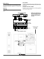
ProductManual Product Manual R QWL3.0 Integrated Building Manager Panel Description Contents • Energy Metering and Monitoring • User definable communication cycles and packet Description . sizes . . . . . . . . . . . . . . . . . . . . . . . . . . . . . . . . . . . . . •Features . SSL (Secure . . . . . . .Socket . . . . . . .Layer) . . . . . .enabled . . . . . . . .web . . . .pages . . . . . . . . •Wiring . Integrated . . . . . controller . . . . . . . . . addressing . . . . . . . . . . . . . . . . . . . . . . . . . . . •Mounting . Multi-port . . .network . . . . . . . capabilities . . . . . . . . . . . . . . . . . . . . . . . . . . . . . •Setup . Energy . . . .demand . . . . . . . .limiting . . . . . . and, . . . . .curtailment . . . . . . . . . . (requires . . . . . . . . . controller firmware Programming . . . . . . . . . 1.4 . . . .or . .later) . . . . . . . . . . . . . . . . . . . . . . •Setting ZigBee Wireless Gateway Clock & Schedule . . . . . . . . . . . . . . . . . . . . . . . . . . . •Program RS232-to-RS485 signalFeatures . converter Options Operating . . for . . . hard-wired . . . . . . . . . . . . RS485 communications Checkout & Troubleshooting . . . . . . . . . . . . . . . . . . . . . . . . • Built-in 2 Amp relays with hand/off/auto switches LED Description . . . . . . . . . . . . . . . . . . . . . . . . . . . . . . . . . . • Supports all TCS Basys Controllers outputs User’s Guide . . . . . . . . . . . . . . . . . . . . . . . . . . . . . . . . . . . . . Ubiquity . . . . . . . . . . . . . . . . . . . . . . . . . . . . . . . . . . . . . . . . The QWL3.0 is a low voltage panel with integrated comThe SZXXXX slru oirhjgdlkf goir orhjgodirjzoz urrihg oiru munication gateway with a central erliroz l k;dkgru erutperforjdjcommunication er jis l Ubiquity server, lighting time-clock and utility meter pulse transducer. The QWL provides a central panel configuration for mounting in a variety of locations. Features Stand-alone or network operation Features 7-day time clock sensor input high and and low limits • Discharge Protectiveairenclosure for with controls instrumentation • Outdoor Eight channel lighting interior exte air sensor input schedules with heatingfor and coolingand lockout rior applications Adjustable delay on powerup for soft starts • P+I Utility meter for monitoring of pulse transducer kW control option and kWh, gas, BTU and water. Smart Recovery reduces energy use on changeover to occu• Integrated controller programming and scheduling pied mode • No Remotely upgradable firmware battery backup required • Minimum 365-day programming each circuit protection on/off times forfor HVAC equipment • 32-character Analog input for photo sensor with the ability to LCD display remotely adjust sensitivity level Six status LEDs • Remote Digital photocell inputs room sensing capability • Astronomical clock User setpoint adjustment limits • Remote or local override of each circuit Local override and remote override capability • External time clock or occupancy sensor input for System and fan switching with access lockouts each circuit Fan interlock safety option • LEDs for monitoring status Filter service input and indication • No battery required for control parameters, schedules Equipment or clock monitoring inputs and indication • Vanishing holidays • Selectable normally open or normally closed relay on outputs • Integrated Web Server with 1 GB of RAM and 80 GB of Storage Capacity • Integrated 10/100 Ethernet controller with firewall capabilities • Embedded simple interface to program and monitor the Controller Network • Standard fallback alarming local to the device Contents 1 2 3 4 5 6 7 8 9 10 11 12 Description . . . . . . . . . . . . . . . . . . . . . . . . . . . . . . . . . . 1 Features . . . . . . . . . . . . . . . . . . . . . . . . . . . . . . . . . . . 1 Mounting . . . . . . . . . . . . . . . . . . . . . . . . . . . . . . . . . . . 2 Wiring . . . . . . . . . . . . . . . . . . . . . . . . . . . . . . . . . . . . . 2 Programming - Lighting Module . . . . . . . . . . . . . . . . . 3 Programming - Pulse Meter . . . . . . . . . . . . . . . . . . . . 6 Mode of Operation . . . . . . . . . . . . . . . . . . . . . . . . . . . . 7 Initial Configuration . . . . . . . . . . . . . . . . . . . . . . . . . . . 7 Prior to Connection to Network . . . . . . . . . . . . . . . . . . 7 RS485 Network Wiring and Setup . . . . . . . . . . . . . . . 8 Setup & Programming . . . . . . . . . . . . . . . . . . . . . . . . . 9 Controller Addressing . . . . . . . . . . . . . . . . . . . . . . . . . 10 Ubiquity Systems Software . . . . . . . . . . . . . . . . . . . . . 10 Wireless Network Setup . . . . . . . . . . . . . . . . . . . . . . . 11 LED Display and Push Buttons . . . . . . . . . . . . . . . . . . 13 Checkout & Troubleshooting . . . . . . . . . . . . . . . . . . . . 14 R 2800 LAURA LANE • MIDDLETON, WI 53562 • (800) 288-9383 • FAX (608) 836-9044 • www.tcsbasys.com 1 Input Wiring The QWL3.0 panel accepts one 0 to 5 VDC input, one 4 to 20mA input, eight dry contact/digital inputs and 4 pulse meter inputs. Mounting The QWL panel is designed for mounting using four #10-12 pan head screws. It is recommended to mount the panel to something of substance (i.e. wall studs, plywood, etc.). Powering the QWL3.0 Panel The QWL3.0 panel is powered from a 120VAC @ 60HZ to 12VDC power supply module. Wiring The QWL3.0 panel terminal designations are shown below. QWL3.0 Panel Wiring DI Board NOTE: Any modifications to the QWL3.0 panel (including drilling out the EMT knockout) will void the product's warranty. Main Board 1" EMT Knockout for use with ¾" Conduit QWL3.0 Panel Layout DI Board Main Board USB to ZigBee Serial to QD1010 A B REF O O O Gateway ON OFF R 2800 LAURA LANE • MIDDLETON, WI 53562 • (800) 288-9383 • FAX (608) 836-9044 • www.tcsbasys.com 2 Programming - Lighting Module The lighting module portion of this panel is an SLQ218. It must be programmed if other than factory default settings are desired. The factory default address is 218. CHANNEL EVENT SCHEDULING There are up to two “ON” periods per day, and thus two time schedules (A and B). There are also up to eight independent channels (depending on model). Let us say that the “ON” time for a particular day is from 8:00AM to 12:00PM and from 1:00PM to 5:00PM. In the A schedule you could enter 8:00 to 12:00, and in the B schedule you could enter 13:00 to 17:00. You can reverse the A and B schedules also. You can also enter 8:00 to 17:00 for the A schedule and 0:00 to 0:00 for the B schedule. 0:00 (12:00AM) starts the day, and 24:00 (12:00AM) ends the day. “ON” times that span midnight have to be coordinated using two days' time schedules. Within the Ubiquity programming page, the desired schedule is simply selected from the drop-down menu for each channel. If the desired schedule is not shown in the drop-down, new schedules can be created or existing schedules can be edited on the Scheduling page. AI1 AMBIENT LIGHT INPUT If using an ambient light sensor (0 to 5, 1 to 5V or 4 to 20mA), set the low and high scaling limits for AI1. These limits are what the light sensor reads at 10W limit and what the light sensor reads at full scale. A Lighting Channel Threshold and Hysteresis for each of the available channels can be set for this input signal. For example, if the input is scaled 0 to 1000 lumens and you want to turn off one channel if the input gets up to 500 lumens and allow it to come back on if the input falls to 400 lumens, enter in 0 for the scaling low limit, 1000 for the scaling high limit, 500 for the threshold and 100 for the hysteresis for that channel. CHANNEL HOLIDAY SETUP Holidays are created as part of the Scheduling page and will appear as part of the selected schedule. You can create date specific holidays, roaming holidays, or select from a list of standard bank holidays. If the selected schedule does not include the desired holiday(s), the schedule can be edited on the Scheduling page. Select a threshold and hysteresis for the channels which will be allowed to be shut off based on this input hitting the threshold. A common application for this feature is to control parking and exterior signage lighting. Essentially the channel will be on all the time it is occupied except when there is too much light. (Similar to the astronomical time function). ENABLE BLINK OUTPUT The Blink Output option forces the respective lighting output turn off and on, four times, five minutes prior to an unoccupied or off period. This will give an indication that a scheduled on time is about to end. Click the checkbox to enable this function for each channel. AI2 ENERGY POWER / INPUT If using an energy meter, power meter or current transducer (4 to 20mA), set the low and high scaling limits for AI2. These limits are what the energy or power meter reads at 4mA and what the energy or power meter reads at 20mA. ENABLE ASTRONOMICAL TIME The Astronomical Time option allows the controller to turn a channel on and off based on the locations sunrise and sunset times. See the Astronomical Time section later in the manual for more details and additional configuration options. Click the checkbox to enable this function for each channel. Select a Lighting Channel Threshold for this input signal. Also select a Lighting Channel Hysteresis for this input signal. For example, if the input is scaled 0 to 10000 KW and you want to turn off some channels if the input gets to 7500 KW and allow them to come back on if the input falls to 6500 KW, enter in 0 for the scaling low limit, 10000 for the scaling high limit, 7500 for the threshold and 1000 for the hysteresis. You should choose this threshold to be larger than the equipment/device being turned off so it does not cycle on and off. WHEN CHANNEL IS “ON”,… You can select how you want the time clock output (Digital Output Mode) to behave when the channel is “ON”. You can choose for the Relay to be Normally Open (Off) or Normally Closed (On) during on periods. Simply select the desired behavior form the drop-down menu. R 2800 LAURA LANE • MIDDLETON, WI 53562 • (800) 288-9383 • FAX (608) 836-9044 • www.tcsbasys.com 3 Select which of the available lighting channels will be allowed to be shut off based on this input hitting the threshold. To setup astronomical time, enter the Latitude and Longitude parameters for the location being controlled. Also enter the time offset from GMT (Greenwich Mean Time). For example, the USA Central Standard time zone is offset -360 minutes from GMT. Madison, Wisconsin, USA is at 43° 5 minutes North (+) Latitude and 98° 30 minutes west (+) Longitude. The GMT Offset range is + 720 Minutes. Also click the box if applying daylight savings time to the astronomical time calculation. AI2 AMBIENT LIGHT INPUT If AI2 is not used for power limiting, a second light sensor can be used to monitor another area. Set the low and high limits for AI2. These limits are the light sensor reading at 4mA and the sensor reading at 20mA respectively. Next, select the channel(s) that should have the astronomical time function and click the Enable box. This is done in the Schedule section of the page. Click on the Enable box for each of the channels to be controlled by channel 2. Then proceed to setup the channel thresholds in the AI1 AMBIENT LIGHT INPUT box and make any desired changes. The channels that are checked as applying to channel two, will be applied to channel two in place of channel one. Note, for non-North American Daylight Savings time set the manual DLS (Day Light Savings) time. CHANNEL OCCUPANT OVERRIDE CHANNEL CONTROL This is the number of minutes from 0 to 255 (4 hr, 15 min) which the controller will bring a system that is Off to On when its override button is pressed. This time can be different for each channel. You can also select whether the Override is Local (the controller manipulates these inputs/output) or Remote (the inputs/output are controlled through the software). If Remote is selected, you will also be able to chose the state of the override (ON or OFF). Note – when doing this, the respective Override will remain in that state indefinitely until you change it from a PC, or set the Override to Local. Select whether you want the Digital Input DI1 and/or Override 1 to be Local or Remote. DI1 and Override 1 are used for Channel 1, DI2 and Override 2 are used for Channel 2, etc. Local means that the lighting module uses its own control program to manipulate these inputs. Remote means that it will take a PC to make any changes to these inputs. If the Digital Control is Remote for DI1, DI2, Override 1, Override 2, etc., you can select whether they are On or Off and force these inputs and outputs on or off from a PC. Note - when doing this, the respective input will remain in that state indefinitely until you change it from a PC, or make the Digital Control Local. HOLIDAY VANISHING Choose whether to enable the Holiday Vanishing Feature. If checked, the controller will make the number of days for a holiday 0 after the holiday is over. This will keep the holiday from occurring in subsequent years if it is not reprogrammed. There are three Digital Input Modes which can be used with a digital input: Regular, External Override & Momentary Toggle Override. With Regular mode, the digital input is used in conjunction with the programmed schedule in determining when the relay output should be on or off. DIGITAL INPUT DELAY/FILTER Enable the Digital Input Delay if you want the Digital Input to be present for 15 seconds before it takes effect. This can prevent cycling. Note, this delay if selected, will apply to all eight channels. With External Override mode, the digital input acts the same as the override button on the panel of the SL2108. The switch used for this type of digital input must be a momentary N.O. switch. POWER DOWN PERIOD With Momentary Toggle Override, the digital input acts like a toggle switch. This must also be a momentary N.O. switch. If the time clock is on, pressing the switch turns it off, If the time clock is off, pressing the switch turns it on. If the controller loses power, it can remember which channels have been overridden and how much time is remaining in each override period. This is the amount of continuous power loss time in minutes where the controller will remember the override status'. If the controller loses power for longer than this period, the override buttons will have to be pressed again as necessary ASTRONOMICAL TIME The Astronomical time function may be setup on any of the channels. It controls and turns off the enabled light channel for the daylight period form sunrise to sunset. The following diagram illustrates the typical application of this capability. INPUT VOLTAGE The input voltage is monitored. The calibration factor is used to scale the controller's 24 VAC power input to the appropriate line voltage. For example, if the line voltage is 120 VAC and the SLQ218 power input is 24 VAC, then the calibration factor is 5.0. If the line voltage is 120 VAC and the controller power input is 27 VAC, then the calibration factor is 4.4 If the line voltage is 277 VAC and the SLQ218 power input is 24 VAC, then the calibration factor is 11.5. R 2800 LAURA LANE • MIDDLETON, WI 53562 • (800) 288-9383 • FAX (608) 836-9044 • www.tcsbasys.com 4 Daylight Savings Time for Channel 2, etc. Local means that the lighting module uses its own control program to manipulate these inputs. Remote means that it will take a PC to make any changes to these inputs. If the Digital Control is Remote for DI1, DI2, Override 1, Override 2, etc., you can select whether they are On or Off and then Write or Write Channel, or Write All Channels and force these inputs and outputs on or off from a PC. Note - when doing this, the respective input will remain in that state indefinitely until you change it from a PC, or make the Digital Control Local. Beginning in 2007, Daylight Saving Time (DST) in the U.S. will be extended by having an earlier change to DST in spring and a delay in switching back to standard time in fall. However, this change may only be temporary, as this "new" schedule is only in effect for a 2 year trial period. After that, the DST schedule may revert back, stay the same, or be something completely different. Products shipped starting in 2007 with firmware version 1.5 or higher accommodate the new DST schedule. Products shipped starting in 2008 with firmware version 2.0 or higher accommodate the new DST schedule and have the ability to be programmed to accommodate any future schedules that may be used. Should the schedule change and you need to customer program the DST start and end dates, simply enable the "Daylight Savings Time" option within the software and enter the starting month + week and the ending month + week. There are three Digital Input Modes which can be used with a digital input: Regular, External Override & Momentary Toggle Override. With Regular mode, the digital input is used in conjunction with the programmed schedule in determining when the relay output should be on or off. With External Override mode, the digital input acts the same as the override button on the panel of the SL2108. The switch used for this type of digital input must be a momentary N.O. switch. BLINK OUTPUT The Blink Output option forces the respective lighting output turn off and on, four times, five minutes prior to an unoccupied or off period. This will give an indication that a scheduled on time is about to end. Select whether to enable this function for each of the eight lighting channels. CHANNEL MONITORING AND CONTROL With Momentary Toggle Override, the digital input acts like a toggle switch. This must also be a momentary N.O. switch. If the time clock is on, pressing the switch turns it off, If the time clock is off, pressing the switch turns it on. Select whether you want the Digital Input DI1 and/or Override 1 to be Local or Remote. DI1 and Override 1 are used for Channel 1, DI2 and Override 2 are used Select whether you want the time clock output (Digital Output Mode) to be Normally Open (Off) or Normally Closed (On) during on periods. R 2800 LAURA LANE • MIDDLETON, WI 53562 • (800) 288-9383 • FAX (608) 836-9044 • www.tcsbasys.com 5 Programming - Pulse Meter Below is a diagram depicting two types of utility meter pulse outputs. Meter Type A counts only the leading edge as a single pulse and the trailing edge is ignored. Meter Type C is known as a true KYZ meter and counts both the leading and trailing edges as a pulse, effectively doubling the number of pulses as seen by Meter Type A. The SEQ100 measures Type A output only; however, KYZ functionality can be mimicked by using a “Meter Multiplier” value of 2. The utility pulse meter module portion of this panel is an SEQ100. In the following picture, both Type A and C are shown. Three pulses are shown, labelled 1, 2, and 3. Notice how the Type A output closes and opens for each pulse, where the Type C output simply changes state. If you have a Type C device (3 terminals KYZ), you will need to double the multiplier. The SEQ100 only counts the contact closures for the K and Z terminals. Doubling the multiplier will correct this problem. METER INPUTS There are four meter inputs available. Each one is setup for a dry contact and cannot be changed. Each input (Meter 1, Meter 2, Meter 3 & Meter 4) can be configured to accept signals representing electrical, BTU, water or gas usage. The required parameters will be provided by either the utility company involved or on the current transducer (CT) used to generate the pulse signal. PROGRAMMING THE METER CONSTANTS: CT Value: The value of the CT wired to the meter. This value is usually provided on the CT or on the utility output meter. This value is only used for and electric meter. METER TYPES P/REV: The Pulses per revolution for the meter. This value is usually provided from the utility company. The SEQ100 supports various meter types. Selecting a meter type changes the default values as they are used to calculate meter consumption and demand for that particular meter. For each of the four SEQ100 meter inputs, there are five selectable options: ELEC 1 PH: Electric single phase meter. ELEC 3 PH: Electric three phase meter. GAS: Gas meter. WATER: Water meter BTU: BTU meter CONSTANT: The value of the constant for the meter is usually provided from the utility company and many times is located on the electric or gas bill. CU FT/P: The value for Cubic Feet per pulse. This only applies to Water, GAS and BTU, and is usually found on the utility meter itself. MULT: The multiplier for the meter can be used to scale the meter output or correct for KYZ meter. The multiplier is used to convert the pulses to engineering unit data. For example, if your meter provides one pulse per 0.01KWH, then a constant of 0.01 is required. Utility pulse meters can be one of two different types, depending on whether they count the leading and trailing edges of the pulse or only the leading edge of the pulse as a single count. A pulse output can be either a mechanical relay or solid state device. The pulse output corresponds to a unit/time of a monitored quantity. The amount of time between states of a pulse output corresponds to the meter demand and the number of pulses is proportional to the meter’s consumption. MULTIPLIER: Each model of power meter is different and has a different multiplier. For example, if the meter is a Type A and reports 1/10 kWh per pulse, set the input multiplier to 0.1. If the meter is a Type C and reports 1/10 kWh per pulse, set the input multiplier to 0.2. You must obtain the correct pulse multiplier from the meter manufacturer prior to configuring the SEQ100. Some power meters have an option to configure the multiplier. Options often include 1, 0.1, 0.01, kWh per pulse. The best method to configure the pulse is to select the smallest multiplier available, considering the maximum load and pulse rate. To calculate the pulse rate, use the following formula: R 2800 LAURA LANE • MIDDLETON, WI 53562 • (800) 288-9383 • FAX (608) 836-9044 • www.tcsbasys.com 6 Initial Configuration Pulses = KW*3600*multiplier Second The QWL3.0 comes from the factory with a default mode of Stand-alone and with a special setup mode enabled. This setup mode is called 'Setup DHCP Server'. In this mode the QWL3.0 acts as a DHCP server of setting up the QWL3.0 by simply connecting to it with a laptop or desktop PC. Caution: The QWL3.0 comes programmed with a default setup mode and functions as a DHCP server. When setting up the unit, be sure it is not connected to another DHCP enabled network. In general, the SEQ100 calculates electric meter consumption and demand as follows: Demand = (CTValue*MtrConst*MtrMult) (PPRValue*PulseTimeDiff) Before connecting the QWL3.0 to a LAN or WAN, you must first configure the unit for operation. To configure the unit, connect it to a PC or laptop that is NOT connected to a network during the configuration process. Make this connection from the Ethernet port of the unit to the Ethernet port of the PC using the CAT 5 crossover Ethernet cable included. After you have made the connection from the QWL3.0 to the PC, power up the unit and wait 3 minutes for the unit to completely boot up. You then need to reboot your laptop or PC to allow it to be assigned an IP address from the unit. Open the web browser program (Internet Explorer v5.0 or higher is the recommended browser). In the browser address space, type in IP address http://192.168.1.1 and press enter to navigate to the unit login page. Enter username: admin and password: password to reach the Ubiquity site home page. From this page you can configure the operation mode of the QWL3.0 (See Setup & Programming section) by navigating to the following links at the top of the home page Admin > QD2040 Setup. You can now change various parameters or link to the control addressing page to address controllers, that do not have displays, prior to installation. (See Control Addressing section) After configuration is complete, disconnect PC from the QWL3.0. It is now ready for installation. Consumption = (PulseCount*CTValue*MtrConst*MtrMult) PPRValue The above diagram depicts how a single pulse and the pulse time difference are represented on a pulse waveform input into the SEQ100. Modes of Operation There are two modes in which the QWL3.0 can operate. One method is stand-alone server mode utilizing the embedded Ubiquity software. The second method is by directly communicating to a centrally hosted Ubiquity server. In stand-alone mode the QWL3.0 functions as the server to the controller network and can be accessed via the Internet, through a local or wide area network (LAN or WAN). All access methods utilize a simple web browser interface. The QWL3.0 may also be accessed via direct connection from a laptop using the included CAT 5 Crossover Patch Cable. Prior to Connection to Network For Internet operation decide how the QWL3.0 will connect. The QWL3.0 can connect to the Internet using a broadband connection (Cable or DSL) or through a LAN. NOTE: Despite its appearance this is a unique cable designed especially for direct connections between two computers. Other Ethernet cables will not work. Ethernet When connecting to a centrally hosted server utilizing the Ethernet port outside of the local or wide area network, it is necessary to verify, with the network administrator, that the proper communication ports are open through the corporate firewall (typically Port 80). The other method of operation for the QWL3.0 is to communicate directly to a centrally hosted Ubiquity server by connecting to the Internet or by connecting to a local or wide area network (LAN or WAN). By connecting to a centrally hosted server, the advantages of multi-site enterprise functionality is achieved. Enterprise features include: multi-site global programming, global scheduling, global alarming and enterprise data aggregation. In addition, some local control functions are still performed by the QWL3.0 (i.e. Loop control, energy curtailment, outdoor air sharing, etc.) Stand-alone When operating in stand-alone mode, it is necessary to establish the URL for the QWL3.0. This is accomplished by utilizing either static or DHCP IP addressing. It is necessary to determine if the unit will be accessible over a network and if so will it utilize DHCP or static IP addressing. When using static IP addressing, it is also necessary to establish the Gateway, Subnet and DNS protocol setting for the unit. This will need to be done by the LAN/WAN network administrator prior to installation. When utilizing DHCP addressing, the IP address settings are automatically assigned when communication is established. R 2800 LAURA LANE • MIDDLETON, WI 53562 • (800) 288-9383 • FAX (608) 836-9044 • www.tcsbasys.com 7 RS485 Network Wiring and Setup When operating in communication to a centrally hosted Ubiquity server through an Ethernet connection, the QWL3.0 supports both static and Dynamic Host Configuration Protocol (DHCP) IP addressing. When using static IP addressing, it is also necessary to establish the Gateway, Subnet and DNS protocol settings. The IP protocol settings will need to be established by the LAN/WAN network administrator prior to installation. When utilizing DHCP addressing, the IP address settings are automatically assigned when communication is established. Configuring the QWL3.0 for DHCP is outlined in the Programming Setup section. To access your controllers through Ubiquity browser software, you will need to create an "RS485" network by connecting all of the controllers "A" terminals together, "B" terminals together and REF together, using 18 or 20 AWG, 120 ohm impedance, twisted, shielded 3 conductor (triple) wire. Controller Network Setup If a port has more than 64 Controllers or is longer than 4000 ft., you will need a bus repeater, QD1011a or use the built-in ZigBee wireless network (limit of 15 wireless units). You will need an additional bus repeater for each wired group of 64 units. All controls connected to the network will need to be programmed with the same communication baud rate as well as a unique communication address from 0 to 255, excluding 248. On units with displays, this can either be done from the face of the controller using the keypad and display or by individually direct connecting controllers to the QWL3.0. On units without displays, controller addressing is done by direct connect to QWL3.0. (see Control Addressing section) When connecting controllers on a network, you may use any wiring configuration (i.e. "daisy chain", "star", etc.), as long as all "A" terminals are connected together, all "B" terminals are connected together and all “Ref” terminals connected together. The integrity of the "A", "B" and “REF” wiring runs must be maintained or the network will not communicate properly. Also, a 120 ohm terminating resister should be installed at the farthest end of the network (one is already built-in on the QWL3.0), CAUTION: You must maintain proper polarity of "A", "B" and "REF" connections. All shields must be tied together, taped off to prevent any accidental connections then grounded at one end of the network. Caution should be taken to avoid running wire near power wires, frequency drives, fluorescent lights, ballasts, etc., which can all compromise the communications signal. Care should also be taken to leave as little wire exposed as possible. Critical: Avoid noise on the communications line by grounding the shield. The signal that passes information is 1 to 5 V. If you measure across A and B, you should get 0 VAC, and 1 to 4 VDC. There should be 0 VAC and 0 VDC between either A on B and the shield. If you are getting more than this, check for runs against high voltage, for exposed wires, to see if grounding at only one side, or that you have used dedicated power for the controllers or if you have reversed power on a Controller(s). NOTE: By using wire cable consisting of one triple of twisted shielded wire and one pair of unshielded wire, you can run power to controllers and run communications wire in the same cable. Part # PM2000A NOTE: Be sure to check any local codes to confirm the wire choice meets the code. The QWL3.0 includes one QD1010 RS232/RS485 communications converter that is attached directly to the serial port and one ZigBee coordinator that is attached directly to the USB port. The controller network wiring connects to the "A", "B" and "REF" terminals on the main board. If using more than one port on the QWL3.0, additional QD1010 devices will need to be used (one per port). When connecting to the USB ports, a PI1000 USB/Serial Converter is required to connect the QD1010 to the USB port of the on the back of the unit. Up to 64 controllers can be placed on a single port of the QWL3.0. Additional USB ports may be provided by the use of a multi-port USB hub attached to the built-in USB port on the unit. R 2800 LAURA LANE • MIDDLETON, WI 53562 • (800) 288-9383 • FAX (608) 836-9044 • www.tcsbasys.com 8 Setup & Programming In this section also enter the SMTP Server settings, POP username and password and a return email address. You can also select when you want the QWL3.0 to communicate with the server by selecting Always On, Never On or Specifying the times. To specify the times, select a cycle time from the drop down menu and then select how long you want the unit to remain online from another drop down menu. Once you have made connection and have logged in you are able to configure the operation of the unit. To program and setup the QWL3.0 when it is in StandAlone / Dial-In mode click on the Admin menu and then click the QD2040 setup tab. Once on the QD2040 setup page you can begin selecting the proper parameters for your application. If the unit is in Ethernet to Central Server mode there will be no access to the menu items of the embedded Ubiquity software. In either case, all Ubiquity Application software and functionality is accessed by logging into the Central Server (www.ubiquitysystems.net) Stand-alone Before you can setup the QWL3.0 to operate in the Stand-alone mode, you must first uncheck the default setting of 'Setup DHCP Server' option. When in Stand-alone mode, the unit functions as a self contained server to the controller network. In this mode the unit can be accessed directly via PC or can be accessed over an Ethernet. Network Commissioning Configuration Select whether the QWL3.0 will operate using a static IP address or DHCP addressing. When using static IP addressing as determined by the LAN/WAN network administrator, you must enter the IP address, Gateway protocol setting, Subnet setting and DNS setting. When using DHCP addressing, no further settings need to be entered in this section. If in either case, you will need to know the IP address needed to access the QWL3.0 (Note: This IP address is most likely different than the IP address that is used when connecting to the unit via the Ethernet port) Once on the login page, enter username: admin and password: password to login to access the local controller network. Enter correct time, date and time zone into the appropriate areas. Also located in this section is the information regarding the MAC address of the Ethernet card in the QWL3.0. This is important when matching DHCP addresses with hardware on the network (see Initial Connection section) (For additional information on using the embedded software in the QWL3.0, see the Ubiquity User Manual.) Communication Configuration Before you can change the mode of operation that the QWL3.0 will be operating in, you must first uncheck the default setting of 'Setup DHCP Server' option. When doing so you will receive a caution box to notify you that after you finish entering setup parameters and click the submit button, the unit will reboot within 5 minutes. There are two modes of operation that the unit can operate in either Ethernet to Central Server or Stand-alone mode. Ethernet to Central Server If Ethernet to Central Server mode is selected, select whether DHCP or static IP addressing is used. If static IP addressing is selected, you must also enter the Gateway, Subnet and DNS protocol settings. You will be required to confirm these settings when submitting the page. Select whether to enable or disable Secure Sockets Layer (SSL) communication with the central server. ALARM DISTRIBUTION You can select up to six different pager/cellphones numbers to be notified in the event of an alarm. You can enter up to six numbers to designate a Site Code. You must then enter in the destination email of up to six different R 2800 LAURA LANE • MIDDLETON, WI 53562 • (800) 288-9383 • FAX (608) 836-9044 • www.tcsbasys.com 9 pagers/cell phones. In the event of an alarm, the QWL3.0 will email the alarm to the appropriate contact(s). button at the bottom of the Controller Addressing page. PORT CONFIGURATION Ubiquity Systems Software The communication ports are automatically detected once the QWL3.0 is powered up. Once detected each COM port needs to be configured to ensure proper functioning of the network on each port. Each port can be enabled or disabled from the drop down menu. You must also select the proper protocol being used on each port. The current protocol selections from the drop down menu are TCS or Modbus Veris Meter. The Modbus Veris Meter selection will support the PE Series Modbus Meters. The Ubiquity system addresses the market’s desire for a fully integrated system in a single, customizable package. Ubiquity can function as an embedded application in the QWL3.0 or as a centrally hosted application that readily and easily interfaces with the local QWL3.0. The system is designed on a modular approach to collect and manage information and data. This strategy provides us the opportunity to effectively package a solution tailored to embrace your most immediate concerns. Plus our advanced controls and monitors, combined with this easily modified modular approach, offers the scalability to effectively meet your future demands. You must also select the communication baud rate for each port. This setting must be the same as all of the controllers on that port. You can also adjust the Time-Out Period for each port. The Time-Out Period is the amount of time, in milliseconds, that the network will wait to send information requests from the controllers on the port before it times out. If time-out errors are occurring on the network you should increase this value until there are no longer time-outs. Generally, the more controllers on a particular network, the higher this value will need to be. The Ubiquity systems modular design incorporates: • • • • • • Energy and environmental management TCS Basys Controls energy management system Automated lighting management Refrigeration and freezer monitoring and alarming Global scheduling, programming and alarming Integrated preventive and reactive maintenance functions Refer to the Ubiquity Manual for further information OTHER PROGRAMMING OPTIONS You must select a Network Polling Cycle Time for the QWL3.0. This is the time interval that the unit will poll the entire network of controllers on all ports (For additional information on using the embedded software in the QWL3.0, see the Ubiquity User Manual.) Wireless Network Setup Controller Addressing The QWL3.0 has a built-in ZigBee wireless gateway, also know as a QW1010A, to manage the ZigBee wireless network. This version , however, comes from the factory in the OFF position. Be sure to move the jumper into the ON position before using the ZigBee Wireless module. (see page 2 for diagram of the Wireless Gateway jumper) Prior to accessing controllers via the network, all controls must be programmed with the same communication baud rate as will be used for the QWL3.0. All controls must also be programmed with a unique communication address from 0 to 255 excluding 248. All controls come with a factory default address of zero. On units with displays, control addressing can be done using the keypad and display or by utilizing the QWL3.0 control addressing interface page. Controllers with no displays need to be addressed through the QWL3.0. To address via the software interface you must first follow the necessary connection procedures to access the unit (see PK3000 Initial Connection section). After initial connection is UPS established and before the controller network is attached to the QWL3.0, only one controller can be attached at a time to the unit (see Control Network Wiring and Setup section for instruction on connecting controllers to the serial or USB ports of the unit) TO INTERNET WALL OUTLET WALL OUTLET REF B A QD2040 COMMUNICATION CENTER QD1010 SERIAL CONVERTER QW1010a WIRELESS GATEWAY OR Throughout wireless setup section the terms coordinator, TO the INTERNET WALL OUTLET gateway, QW1010A, and QWL3.0 will be understood to mean the same thing and will be used interchangeably. To access the addressing page press Controller Addressing button at the bottom of the unit Setup page. Select which port you are connected to from the drop down menu. If you know the current address of the controller, select the number from the drop down (all controllers come from the factory with a default address of 0) menu then select the new address you wantPK3000 to give the controller from the other drop down menu. IfUPS the current address is not known, select the desired address from the drop down menu. When finished press the submit Location: • A wireless network will not function correctly if it is separated by walls or other structures in which a wireless signal QD2040 QW1010a cannot penetrate such as steel, concrete, or rocks. REF B A COMMUNICATION CENTER R THEN 2800 LAURA LANE • MIDDLETON, WI 53562 • (800) 288-9383 • FAX (608) 836-9044 • www.tcsbasys.com WALL OUTLET REF B A 10 WIRELESS GATEWAY • The area containing wireless devices should be static/ non-changing, for example, do not place wireless devices behind a steel door that is open during occupied times and closed during unoccupied times. • No part of a wireless network should be placed outdoors. The varying atmospheric conditions cause the wireless signals to distort resulting in an unstable wireless network; for example, a wireless network formed on a foggy day will have trouble communicating on a clear day and vice-versa. • The coordinator of the wireless network should be placed at a central location with respect to the routers. • Coordinators and routers should be placed in an area with little external wireless interference, away from other wireless devices. module removed. 5. Set a unique TCS address on the router. 6. Remove power from the wireless thermostat/router and install the wireless module. 7. Power up the wireless router. 8. Repeat steps 2-6 for all the wireless routers on the network, being sure that each router has a unique TCS address. Install the routers so that each anticipated first hop is powered first, followed by the anticipated second hops, etc. Start Insight by clicking on the icon on the desktop or going to: Start->All Programs-> TCS Basys Controls->Insight Insight Startup Window Select a serial port from the list displayed and select the Open Port button. Leave the controller address and message speed box at their default. Distance: • A wireless network will not function correctly if the distance between the coordinator and/or routers exceeds approximately 150 feet line of sight. Walls or other barriers will QWL3.0 Panel severely limit the maximum distance. • Wireless networks are only able to travel a maximum of 5 hops from the coordinator; routers placed beyond the 5 hop limit will not join the network. • Routers are only able to have 6 children each. Special Considerations: • A wireless network should be oriented in such a way that routers are spread out equidistant in a circular pattern from the coordinator so as to maximize the communicating area available. Routers placed in a straight line may cause network instability. • A Universal Subsystem should never be placed on a wireless network because a subsystem is dependent on uninterrupted continuous communication. • Only 15 routers should be placed on a single wireless network. A router is defined as a wireless thermostat, bridge, or repeater. Large networks cause the wireless communication to become unstable. • If multiple wireless networks are present, each network should be given a separate Personal Area Network Identification (PAN ID) and wireless channel. Wireless channels should be chosen in a way so as to limit interference from other area neighbouring channels, for example, instead of using channels 11 and 12 use channels 11 and 25 or 11 and 14. Wireless Deployment Overview: 1. Power up the QW1010A/Coordinator. Important!! Do not connect the coordinator to the QD2040. 2. Set the desired network PAN ID and Channel on the Coordinator. 3. Move the thermostat/router to the installation location. 4. Power up the wireless thermostat/router with the wireless R 2800 LAURA LANE • MIDDLETON, WI 53562 • (800) 288-9383 • FAX (608) 836-9044 • www.tcsbasys.com 11 Opening ZigBee Module Tab Select Modules from the menu, then select ZigBee from the drop down list. A new tab will be added to the tab list named ZigBee Wireless. Set Channel List for Wireless Network Get the channel list, and set the channels you want the wireless network to be able to use. If only a single wireless network is present, the network will automatically pick the best channel among the channels that you have selected. To force the network to use a specific channel select only one channel from the list. Hit the set button, then the Get button to verify the channel list you have selected. Retrieve Router Information After the router has a unique TCS address, connect the QD1010 to each router using the RS485 via phone jack or terminal blocks located on the bottom board. Select the “Get” button for the Device Type and Firmware Version, verify that it displays router and the current firmware version as shown. Reset Device Once the router PAN ID and wireless channel have been set correctly, select the Reset tab and click on the “Clear Tables and Software Reset” button. Resetting the Router/Gateway will save the settings programmed into it. Set PAN ID and Channel for Wireless Network On the Network Node tab set the PAN ID on each router to that of your network. In this example, the PAN ID is set to 828. It is important that each router and the gateway be set to the same PAN ID otherwise nodes will not be able to join the wireless network. A different PAN ID should be given to each wireless network in a given area. Each time the network, PAN ID, Channel list, etc have changed a “Clear Tables and Software Reset” is required to accept the changes. Hit the set button once you have set the PAN ID, hit the get button to verify that it was successfully set. It is a good idea to record the IEEE Address of each of your routers for future reference. R 2800 LAURA LANE • MIDDLETON, WI 53562 • (800) 288-9383 • FAX (608) 836-9044 • www.tcsbasys.com 12 LED Display and Push Buttons Set the PAN ID and channel list for each device in the wireless network. Once all the routers have been programmed and the network has had enough time to form (approximately 2 min for each node), connect the QW1010 to the computer running the Insight software. In the wireless module tab, click the “Poll Network” button. A network view window will pop up. After 8.00 (approximately in. the network view window has loaded fully 30 seconds) it should look similar to the picture. The blue dots displayed on the network view window represent the wireless nodes on the network. By hovering the mouse pointer over each node it is possible to see the TCS as well as ZigBee address. If a node does not have a valid TCS address or is a repeater, it will be displayed in a yellow green color. If all the nodes in the wireless network are accounted for and show up in blue, then the wireless network is functioning correctly and the Coordinator 14 in. can be connected to the QD2040. 4 5 7 8 Wireless Network View The ZigBee tree will also be displayed as a list view in the ZigBee tab. When an address is selected from the network list that nodes, children can be displayed by pressing the get button 12.50 in. next to the ZigBee children box. CPU RESET RX 6 ALARM 3 WIRELESS 2 TX 1 POWER CH | ON | OVR | DESCRIPTION Fourteen LEDs on the QWL 3.0 allow the user to view the current operating status of the QWL 3.0. DIGITAL OUTPUTS: Along the Left hand side there are Eight LEDs and Push button When one of the ZigBee addresses is selected in the poll network box it will appear in the ZigBee address section of the page. Once the address is displayed in the ZigBee Address box that addresses device type, firmware version, LQI, etc. can be retrieved by hitting the associated get button. • The LEDs will be lit when the corresponding relay output is occupied, or physically on no matter if the channel is selected to be NO or NC. • The pushbuttons correspond to each of the channels for the timed override function. DATA: Along the Right hand side towards the bottom, there are three LEDs • The RX LED indicated that the hard wired RS485 network is in Receive mode. • The TX LED indicated that the hard wired RS485 network is in transmit mode. • The Wireless LED indicates activity on the ZigBee wires network. ALARM: This LED indicates that a local alarm is active 19.50 in. POWER: This LED indicated that the QWL 3.0 has power applied • 21.50 in. The reset button in the lower right hand corner is used to “reboot” the entire QWL 3.0 panel. This is accomplished by pushing and holding the button for 5-7 seconds. Please note: The lights associated with the Lighting Module of this product could go out, it is recommended that you open the panel and place the Hand-Off-Auto switch for the corresponding channel in the Hand position to ensure that the lights that should be on remain on. CPU: This LED indicates that the CPU or QD2040 portion of the panel is active and running. 24 in. R 2800 LAURA LANE • MIDDLETON, WI 53562 • (800) 288-9383 • FAX (608) 836-9044 • www.tcsbasys.com 13 Checkout & Troubleshooting Site Communications Center - QD2040 QWL3.0 • Be sure to check and verify all wiring before powering up the QWL 3.0 • Be sure that if you drilled any holes and created metal shaving that they are all cleaned up and in a position to allow for shorting before powering up. Verify all wiring before powering up the QWL 3.0 and the SLQ218. • Place the Hand-Off-Auto switches in the off position • Place the appropriate (Normally Open) NO or (Normally Closed) NC jumpers (both included) in position-RED wires = NO-ON=Closed and BLACK wires=NC-On=Open Verify all wiring prior to powering the QWL 3.0 and SEQ100. • Take note of the current readings for all meters. Since the SEQ100 is used for only monitoring, and is the reading appear to be correct, you are done. • If a value does not appears to be correct, verify on the programming page the value programmed in is correct. • If a value is shown as 0 (Zero) the SEQ100 is not receiving a pulse signal. • If the CPU LED does not light up, verify that the power supply nodule (included with the QWL 3.0) is plugged in to an outlet that has power. RS232/RS485 Communications Convertor - QD1010 Once a network is wired, you should test communications with all controllers on the network. Find out which controllers communicate and which ones don't. Go to the controllers that don't communicate and verify that the "A" and "B" wires are not switched. Verify the address and the baud rate as well. One of these three things is usually the problem. (see chart below) Utility Meter Pulse transducer Module - SEQ100 • Be sure to verify all wiring and programming information before hooking up to Network If you have the Power Supply plugged into a UPS (Uninterruptable Power Supply - PK3000 or PK3100) make sure the UPS is turned on. Lighting Module - SLQ218 • • IF THEN Tx LED blinks, Rx LED is always off. If this happens, the computer is sending, but the controller is not responding. Check that the baud rate set on the controller(s) are all set the same. Verify controller address. Both Tx and Rx LEDs will blink. Both the computer and the Check wiring. Make sure that communication wircontroller are responding, but you still receive communica- ing runs are at least 5' away from fluorescent lights, motors, etc. Make sure that all controllers on a nettion errors. work have a unique address. Rx LED is always on. This is typically a problem with wiring. Make sure that the "A" and "B" wires are not switched or shorted. Make sure that there is no stray voltage on the "A" and "B" wires. "B" to "A" should measure between 0.5 VDC and 3.6 VDC. "B" to "A" should measure 0 VAC. "A" to "Shield" and "B" to "Shield" should measure 0 VAC and 0 VDC. Communication errors/problems. On smaller networks, try removing one of the two terminating resistors. C3786_REV3 R 2800 LAURA LANE • MIDDLETON, WI 53562 • (800) 288-9383 • FAX (608) 836-9044 • www.tcsbasys.com 14 Rev:0112