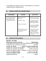
1
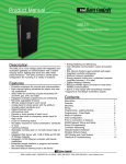
OWNER’S MANUAL
Power Inverter Models
PI-1000 and PI-1500
Converts 12V DC Battery Power to
120V AC Household Power
CAUTION:
Before using your inverter, Read, Understand and Follow all Safety and Operating Instructions. Save These
Instructions.
Schumacher Electric Corporation
Mount Prospect, Illinois 60056 U.S.A.
Send Warranty Product Repairs to:
Customer Service Returns
P.O. Box 280
1025 E. Thompson
Hoopeston, IL 60942-0280
Questions? Call Customer Service:
1-800-621-5485 (Hours: 7:00 am to 5:00 pm CST)
00-99-000901-0409
TRADEMARK ACKNOWLEDGEMENTS
TRADEMARK ACKNOWLEDGEMENTS
Schumacher® is a registered trademark of Schumacher Electric
Corporation
Schumacher® Logo is a registered trademark of Schumacher
Electric Corporation
PI-1000 and PI-1500 ™ is a trademark of
Schumacher Electric Corporation
COPYRIGHT INFORMATION
PI-1000 and PI-1500 Owner’s Manual
© 2008 Schumacher Electric Corporation
The information, specifications and illustrations in this manual are
based on the latest information available at the time of printing.
Table of Contents
Sectionpage
IMPORTANT SAFETY INSTRUCTIONS
5
INVERTER FEATURES
6
FASTENING THE INVERTER TO A FLAT SURFACE
7
GROUNDING THE INVERTER
8
BEFORE USING YOUR POWER INVERTER
9
CONNECTING INVERTER CABLES
10
USING THE GFCI OUTLET (MODEL PI-1500 ONLY)
11
OPERATING INSTRUCTIONS
12
POWER SOURCE
14
HOW DO POWER INVERTERS WORK
15
LED INDICATORS AND SHUTDOWN PROTECTION
15
IF THE INVERTER FUSE BLOWS
16
Troubleshooting
17
SPECIFICATIONS
17
REPLACEMENT PARTS
18
LIMITED WARRANTY
18
1.
IMPORTANT SAFETY INSTRUCTIONS
SAVE THESE INSTRUCTIONS
• Keep the inverter well ventilated in order to properly
disperse heat generated while it is in use. Make sure
there are several inches of clearance around the top
and sides and do not block the slots of the inverter.
• Make sure the inverter is not close to any potential
source of flammable fumes, gases or clothing.
• Do not place the inverter in areas such as battery
compartments or engine compartments where fumes
or gases may accumulate.
• Keep the inverter dry.
• DO NOT allow the inverter to come into contact with
rain or moisture.
• DO NOT operate the inverter if you, the inverter, the
device being operated or any other surfaces that may
come into contact with any power source are wet.
Water and many other liquids can conduct electricity,
which may lead to serious injury or death.
• Do not place the inverter on or near heating vents,
radiators or other sources of heat or flammable
materials.
• Do not place the inverter in direct sunlight. The ideal
air temperature for operation is between 50° and
80°F.
• Only connect the power inverter to a 12-volt accessory outlet or 12-volt airplane power outlet. Do not
attempt to connect the inverter to any other power
source, including an AC power source. Connecting
to a 6-volt or 16-volt battery will cause damage to the
inverter.
• Make sure the AC plug is tight.
• Do not modify the AC receptacle in any way.
•5•
• Do not try extending or otherwise changing the 12volt power cord attached to your inverter.
• Incorrect operation of your inverter may result in
damage and personal injury. WARNING: The inverter
output is 120V AC and can shock or electrocute the
same as any ordinary household AC wall outlet.
• Do not open – No user serviceable parts inside.
• This device does not include an internal Ground
Fault Circuit Interrupter (GFCI). For GFCI protection,
use a Coleman Cable 02822 GFCI outlet (Model PI1000 only).
WARNING: Pursuant to California Proposition 65,
this product contains chemicals known to the State of
California to cause cancer and birth defects or other
reproductive harm.
2.
INVERTER FEATURES
1. ON/OFF Rocker Switch – Turns the inverter ON
and OFF.
2. LED Indicator Light – (Green = power ON, Red =
Overload, interruption in power.
3. 12-Volt Power Cord – One pair
4. 120V AC Outlet – Two Standard (Model PI-1000)
Two GFCI (Model PI-1500)
5. High-Speed Cooling Fan(s) – Keeps the inverter
cool. The speed of the fan is faster as the load
increases. The fan does not run when the inverter is
turned OFF.
•6•
6. Analog Output Power Display – Shows 120V AC
continuous power consumed. Five lights indicate half
of the continuous output power and ten lights indicate
full continuous power consumption. When the inverter
is OFF, no lights appear.
7. Positive Battery Cable Terminal (Red) – Accepts
Positive connector cable.
8. Negative Battery Cable Terminal (Black) – Accepts
Negative connector cable.
9. Ground Terminal – Grounds inverter to reduce
electrical shock.
10. Thermal Protection – When the inverter case becomes hot (exceeds 145° F) the inverter shuts down.
11. Surge Protection – When the power input from the
vehicle’s battery exceeds 15-volts the inverter shuts
down.
12. Low-Battery Protection – When the power input
from the vehicle’s battery drops to approximately
10-volts the inverter shuts down.
3.
FASTENING THE INVERTER TO A FLAT
SURFACE
For convenience your inverter can be fastened to a flat
surface, horizontally or vertically. The area where the
inverter is to be fastened must be dry, well ventilated and
away from any combustible material or fumes.
1. Turn off and disconnect the inverter.
2. Place the back of the inverter with the mounting
bracket against a secure and flat surface.
•7•
3. Attach the inverter to the flat surface using corrosion resistant screws.
4.
GROUNDING THE INVERTER
To avoid electrical shock, it is necessary to ground the
inverter as well as the device powering it. The inverter
should be grounded using a #8 AWG copper wire (not
included).
NOTE: Do not turn on the inverter or the power source
until the inverter and the power source are grounded. To
ground the inverter:
1. Turn off and disconnect the inverter.
2. Locate the chassis ground screw below the negative terminal on the left side of the inverter, remove
the outer hex nut and loosen the second hex nut.
3. Strip the insulation of the #8 AWG copper wire back
1.5” and wrap the bare end of the wire around the
ground screw between the two washers.
4. While holding the wire in place, tighten the hex nut
you loosened securely. Then, replace the other hex
nut and tighten it securely.
5. Attach the other end of the wire to a properly
grounded location, as described next:
A. VEHICLE: Connect to the chassis, unpainted
frame part, or engine block of the vehicle.
B. BOAT: Connect to the boat grounding system.
C. FIXED LOCATION: Connect to a ground rod
or other appropriately rated ground.
•8•
5.
BEFORE USING YOUR POWER INVERTER
When you turn on a device or a tool that runs on a motor, the device basically goes through two stages:
1. Start Up – Requiring an initial surge of power (commonly known as the “starting or peak load”).
2. Continuous Operation – Power consumption drops
(commonly known as the “continuous load”).
The wattage (WATTS) or amperes (AMPS) can normally
be found stamped or printed on most devices and equipment, or in the user’s manual. Otherwise, contact the
manufacturer to find out whether the device you want to
use is compatible with a modified sine wave.
To calculate the wattage: Wattage = AMPS x 120 (AC
Voltage).
To calculate the starting load: Starting Load = 2 x
WATTS. In general, the start up load of the device or
power tool determines whether your inverter has the
capability to power it.
To calculate the continuous load: Continuous Load =
AMPS x 120 (AC Voltage).
Attention: Always run a test to establish whether the
inverter will operate a particular piece of equipment or
device. In the event of a power overload, the inverter is
designed to automatically shut down. This safety feature
prevents damaging the inverter while testing devices and
equipment within the wattage range of the inverter.
If a device does not operate properly when first connected to the inverter, turn the inverter rocker switch ON
(I), OFF (O), and ON (I) again in quick succession. If this
•9•
procedure is not successful, it is likely that the inverter
does not have the required capacity to operate the device in question.
6.
CONNECTING INVERTER CABLES
The inverter and power source must be in the OFF
mode.
IMPORTANT: Make sure you connect your inverter to a
12-volt power supply only.
1. Locate the Positive and Negative plastic terminals
located on the left side of the inverter. Using a standard (flathead) screwdriver, unscrew the positive (red)
and negative (black) terminal screws just enough to
be able to insert the bare end of the connector cables.
2. Insert the bare end of the positive (red) cable into
the positive (red) terminal. Insert the bare end of the
negative (black) cable into the negative (black) terminal. Tighten each terminal screw so that the cable
cannot come loose.
CONNECTING INVERTER CABLES TO 12V BATTERY
OR 12V POWER SOURCE:
1. Keep hands, hair, clothing and jewelry clear of battery terminals.
2. Wear eye protection and clothing protection.
3. Connect the negative (black) inverter terminal cable
to the power source negative (-) or battery terminal.
Make sure the connection is secure.
4. Connect the positive (red) inverter terminal cable
to the power source positive (+) or battery terminal.
Make sure the connection is secure.
• 10 •
5.To disconnect the inverter, reverse the above steps.
NOTE: The internal speaker may make a brief “beep”
when the inverter is being connected to or disconnected
from the 12-volt power source.
ATTENTION: Failure to make the correct connections
will result in blown fuses and permanent damage to the
inverter.
7.
USING THE GFCI OUTLET (MODEL PI-1500
ONLY)
The PI-1500 inverter includes two “GFCI” (Ground Fault
Circuit Interrupter) outlets located on the right side of the
inverter. The purpose of a GFCI outlet is to quickly stop
the flow of electricity in the event a ground fault occurs
on the device plugged into the inverter’s GFCI outlet.
Use only 3-prong grounded plug when using the GFCI
outlet.
The GFCI outlets provide auxiliary power to 120V AC
devices that require less than 15-amps.
The GFCI outlets provide auxiliary power to 120V AC devices that require less than 15 amp. If using both GFCI
outlets at the same time, the amperage cannot exceed a
total of 15 amps for both devices combined.
The GFCI (Ground Fault Circuit Interrupter) must be
tested before each use. To test:
1. Connect the inverter (see “CONNECTING INVERTER CABLES” section).
2. Turn the inverter on.
3. Push the “Reset” button located on the GFCI receptacle, first to assure normal GFCI operation.
• 11 •
4. Plug a nightlight (with an ON/OFF switch) or other
device (such as a lamp) into the GFCI receptacle and
turn the device “ON”.
5. Push the “Test” button located on the GFCI receptacle. The nightlight or other device should go “OFF”.
6. Push the “Reset” button and the light or other device should go ”ON” again.
NOTE: If the light or other device remains “ON” when the
“Test” button is pushed, the GFCI is not working properly
and should not be used. Call Customer Service.
8.
OPERATING INSTRUCTIONS
1. Connect the inverter (see “CONNECTING INVERTER CABLES” section.
2. Switch the inverter switch to the ON (I) position.
3. The LED indicator light should glow GREEN verifying the inverter is receiving power.
4. Turn the inverter rocker switch to the OFF (O) position. (The GREEN LED power indicator light may flash
briefly and/or the internal speaker may make a brief
“beep”. This is normal.).
5. Make sure the device to be operated is turned OFF.
6. Plug the device into the inverter AC outlet.
7. Turn the inverter on.
8. Turn the device on.
9. To disconnect, reverse the above procedure.
• 12 •
NOTE: If more than one device is to be powered,
start one device at a time to avoid a power surge and
overloading the inverter. The surge load of each device
should not exceed the inverters Continuous Operation
wattage rate.
IMPORTANT: If you are using the power inverter to
operate a battery charger, monitor the temperature of
the battery charger for about 10 minutes. If the battery
charger becomes abnormally warm, disconnect it from
the inverter immediately.
NOTE: You can use an extension cord from the inverter
to the device without significantly decreasing the power
being generated by the inverter. For best operating
results, the extension cord should be no longer than 50
feet.
Using the Inverter to Operate a TV or Audio Device:
The inverter is shielded and filtered to minimize signal
interference. Despite this, some interference may occur
with your television picture, especially with weak signals.
Below are some suggestions to try and improve reception.
1. Make sure the television antenna produces a clear
signal under normal operating conditions (i.e. at home
plugged into a standard 120-volt AC wall outlet). Also,
ensure that the antenna cable is adequately shielded
and of good quality.
2. Try altering the position of the inverter, antenna
cables, and television power cord. Add an extension cord from the inverter to the TV so as to isolate
its power cord and antenna cables from the 12-volt
power source.
• 13 •
3. Try coiling the television power cord and the input
cables running from the 12-volt power source to the
inverter.
4. Affix one or several “Ferrite Data Line Filters” to the
television power cord. Ferrite Data Line Filters can be
purchased at most electronic supply stores.
5. Try grounding the inverter with an 18 AWG (minimum) wire, using as short a length as possible.
NOTE: You may hear a “buzzing” sound being emitted
from inexpensive sound systems when operated with the
inverter. This is due to ineffective filters in the sound system’s power supply. Unfortunately, this problem can only
be resolved by purchasing a sound system with a higher
quality power supply or higher quality filter.
9.
POWER SOURCE
Your average automobile or marine battery at full charge
will provide an ample power supply to the inverter for
approximately 3 hours when the engine is off. The actual
length of time the inverter will function depends on the
age and condition of the battery and the power demand
being placed by the device being operated with the
inverter.
If you decide to use the inverter while the engine is off,
we recommend you turn OFF the device plugged into
the inverter and disconnect the inverter’s plug from
the 12-volt accessory outlet before starting the engine.
To maintain battery power, start the engine every 2 to
3 hours and let it run for approximately 10 minutes to
recharge the battery.
• 14 •
Although it is not necessary to disconnect the inverter
when turning over the engine, it may briefly cease to
operate as the battery voltage decreases. While the
inverter draws very low amperage when not in use, it
should be unplugged to avoid battery drain.
10. HOW DO POWER INVERTERS WORK
There are two stages involved in transforming 12-volt
DC (battery) power into 120-volt AC (household voltage):
STAGE 1: The power inverter uses a DC to DC transformer to increase the 12-volt DC input voltage from the
power source to 145-volt DC.
STAGE 2: The inverter then converts the 145-volt DC
into 120-volts AC (household voltage) using advanced
MOSFET transistors in a full bridge configuration. A
“modified sine wave” waveform is generated by this
conversion.
11.
LED INDICATORS AND SHUTDOWN
PROTECTION
The GREEN LED lights automatically when plugged into
a 12-volt DC source and turned on. The RED LED lights,
an audible alarm sounds, and the inverter automatically
turns itself off under the following conditions:
1. When the power input from the vehicle’s battery
drops to approximately 10-volts, low battery shutdown
occurs. (When the power input drops to 10.5-volts,
an alarm will sound for an extended period). Solution:
Recharge or Replace the battery.
• 15 •
2. When the power input from the vehicle’s battery
exceeds 15-volts, high voltage overload protection occurs. Solution: Reduce the voltage range to between
12-volts and 14-volts.
3. The continuous load demand from the equipment
or device being operated exceeds the continuous
load rating of the inverter being used. Solution: Use a
higher capacity inverter or lower rated device.
4. The case temperature becomes hot (exceeds
145°F). Your inverter is fitted with a cooling fan that
runs as needed while the inverter is operating. If the
cooling fan is unable to maintain a cool enough temperature for safe operation, the inverter will automatically shutdown. Solution: Allow the inverter to cool. Do
not block the cooling slots or air flow over and through
the inverter. Reduce the load on the inverter to the
continuous rated output.
RESET: To reset after shutdown occurs, turn the inverter
rocker switch to the OFF (O) position. Check the source
of the problem and correct. Turn the inverter switch to
the ON (I) position.
12. IF THE INVERTER FUSE BLOWS
Your power inverter is fitted with a fuse, which should
not have to be replaced under normal operating conditions. A blown fuse is usually caused by reverse polarity
or a short circuit within the device or equipment being
operated.
If the fuse does blow, take the inverter to a qualified
technician for repair.
• 16 •
13. Troubleshooting
PROBLEM
Red LED is on, audible
alarm is on, and/or inverter does not function.
REASON
SOLUTION
Poor contact at terminals.
Check the connections at
power supply.
Fuse Blown.
See “IF THE INVERTER
FUSE BLOWS” section.
Inverter shutdown.
See “LED INDICATOR
AND SHUTDOWN PROTECTION” section.
Inverter may not be working properly.
See Warranty and call
Customer Service 1-800621-5485 (Hours: 7:00
am – 5:00 pm CST).
14. SPECIFICATIONS
Model: PI-1000
Maximum Continuous Power
1000 Watts
Surge Capability (Peak Power)
2000 Watts
No Load Current Draw
<0.25A
Wave Form
Modified Sine Wave
Input Voltage Range
10.5V – 15.5V DC
Output Voltage Range
120V ± 5% AC
Low Battery Alarm
Audible, 10.3V – 10.6V DC
Low Battery Shutdown
10.5V ± .5V DC
High Battery Shutdown
15.0V – 16.0V DC
Optimum Efficiency
>80%
AC Outlet
Two, 120V AC 3-Prong
Dimensions
10.5” L x 9” W x 3.75” H
Weight
approximately 7.25 lbs.
• 17 •
Model: PI-1500
Maximum Continuous Power
1500 Watts
Surge Capability (Peak Power)
3000 Watts
No Load Current Draw
<0.3A
Wave Form
Modified Sine Wave
Input Voltage Range
10.5V – 15.5V DC
Output Voltage Range
120V ± 5% AC
Low Battery Alarm
Audible, 10.3V – 10.6V DC
Low Battery Shutdown
10.5V ± .5V DC
High Battery Shutdown
15.0V – 16.0V DC
Optimum Efficiency
>80%
AC Outlet
Two, 120V AC 3-Prong GFCI
Dimensions
11” L x 9.5” W x 3.75” H
Weight
approximately 7.9 lbs.
15. REPLACEMENT PARTS
Fuses – Replacement fuses can be purchased at most
electronic component retailers.
Battery Cable with Clamp – Positive (Red)
38-99-002012
Battery Cable with Clamp – Negative (Black)
38-99-002013
16. LIMITED WARRANTY
SCHUMACHER ELECTRIC CORPORATION, 801 BUSINESS CENTER DRIVE, MOUNT PROSPECT, IL 600562179, MAKES THIS LIMITED WARRANTY TO THE
ORIGINAL RETAIL PURCHASER OF THIS PRODUCT.
THIS LIMITED WARRANTY IS NOT TRANSFERABLE
OR ASSIGNABLE.
• 18 •
Schumacher Electric Corporation (the “Manufacturer”)
warrants this inverter for two years from the date of
purchase at retail against defective material or workmanship that may occur under normal use and care. If your
unit is not free from defective material or workmanship,
Manufacturers obligation under this warranty is solely
to repair or replace your product, with a new or reconditioned unit, at the option of the Manufacturer. It is the
obligation of the purchaser to forward the unit, along
with mailing charges prepaid to the Manufacturer or its
authorized representatives in order for repair or replacement to occur.
Manufacturer does not provide any warranty for any
accessories used with this product that are not manufactured by Schumacher Electric Corporation and approved
for use with this product. This Limited Warranty is void if
the product is misused, subjected to careless handling,
repaired, or modified by anyone other than Manufacturer
or if this unit is resold through an unauthorized retailer.
Manufacturer makes no other warranties, including,
but not limited to, express, implied or statutory warranties, including without limitation, any implied warranty
of merchantability or implied warranty of fitness for a
particular purpose. Further, Manufacturer shall not be liable for any incidental, special or consequential damage
claims incurred by purchasers, users or others associated with this product, including, but not limited to, lost
profits, revenues, anticipated sales, business opportunities, goodwill, business interruption and any other injury
or damage. Any and all such warranties, other than the
limited warranty included herein, are hereby expressly
disclaimed and excluded. Some states do not allow the
exclusion or limitation of incidental or consequential
damages or length of implied warranty, so the above
• 19 •
limitations or exclusions may not apply to you. This warranty gives you specific legal rights and it is possible you
may have other rights which vary from this warranty.
THIS LIMITED WARRANTY IS THE ONLY EXPRESS
LIMITED WARRANTY AND THE MANUFACTURER
NEITHER ASSUMES OR AUTHORIZES ANYONE
TO ASSUME OR MAKE ANY OTHER OBLIGATION
TOWARDS THE PRODUCT OTHER THAN THIS WARRANTY.
Schumacher Electric Corporation Customer Service
1-800-621-5485
Monday – Friday 7:00 a.m. to 5:00 p.m. CST
• 20 •
• 21 •
• 22 •
MANUAL DEL PROPIETARIO
MODELOS DE CONVERTIDOR DE ENERGÍA
PI-1000 y PI-1500
Convierte la Energía de Baterías de 12V de CD
a 120V de CA de Energía Doméstica
PRECAUCIÓN:
Antes de usar su convertidor, Lea, Entienda y Siga todas
las instrucciones De Seguridad y Operación. Guarde
Estas Instrucciones.
Schumacher Electric Corporation
Mount Prospect, Illinois 60056 U.S.A.
Envíe las Reparaciones de Garantía del Producto a:
Servicio al Cliente Devoluciones
P.O. Box 280
1025 E. Thompson
Hoopeston, IL 60942-0280
¿Preguntas? Llame al Servicio de Atención al Cliente:
1-800-621-5485 (Horario: De 7:00 a.m. a 5:00 p.m.
CST(Tiempo del Centro))
RECONOCIMIENTOS DE MARCAS DE FÁBRICA
RECONOCIMIENTOS DE MARCAS DE FÁBRICA
Schumacher® es marca registrada de la Schumacher Electric
Corporation
Schumacher® Logo es marca registrada de la Schumacher
Electric Corporation
PI-1000 y PI-1500™ es marca de la
Schumacher Electric Corporation
DATOS DE PROPIEDAD INTELECTUAL
PI-1000 y PI-1500 Owner’s Manual
© 2008 Schumacher Electric
Corporation
La información, las especificaciones y las ilustraciones en el
presente manual se basan en la información más al día disponible
a la hora de imprimir.
ÍNDICE
SECCIÓN
PÀGINA
INSTRUCCIONES IMPORTANTES DE SEGURIDAD
27
CARACTERÍSTICAS DEL CONVERTIDOR
28
PARA SUJETAR EL CONVERTIDOR A UNA
SUPERFICIE PLANA
30
PARA CONECTAR EL CONVERTIDOR A TIERRA
30
ANTES DE USAR SU CONVERTIDOR DE ENERGÍA
31
PARA CONECTAR LOS CABLES DEL CONVERTIDOR
33
PARA USAR LA TOMA DE CORRIENTE GFCI
(SOLAMENTE MODELO PI-1500)
34
INSTRUCCIONES DE OPERACIÓN
35
FUENTE DE ENERGÍA
38
CÓMO FUNCIONAN LOS CONVERTIDORES DE
CORRIENTE
39
INDICADOR LED Y PROTECCIÓN DE APAGADO
39
SI SE QUEMA EL FUSIBLE DEL CONVERTIDOR
40
RESOLUCIÓN DE PROBLEMAS
41
ESPECIFICACIONES
41
PIEZAS DE REPUESTO
42
GARANTÍA LIMITADA
42
1.
INSTRUCCIONES IMPORTANTES
DE SEGURIDAD
GUARDE ESTAS INSTRUCCIONES
• Mantenga el convertidor bien ventilado para dispersar apropiadamente el calor generado cuando está
en uso. Asegúrese de que haya varias pulgadas de
libramiento alrededor de la parte superior y lados y
no bloquee las ranuras del convertidor.
• Asegúrese de que el convertidor no esté cerca de
ninguna fuente potencial de gases inflamables,
gases o ropa.
• No coloque el convertidor en áreas tales como compartimientos de baterías o compartimientos del motor
donde los vapores o gases pueden acumularse.
• Mantenga el convertidor seco.
• NO OPERE el convertidor si usted, el convertidor, el
dispositivo a ser operado o cualquier otra superficie
puede entrar en contacto con cualquier fuente de
energía que está húmeda. El agua y muchos otros
líquidos pueden conducir electricidad, lo cual puede
llevar a una lesión seria o la muerte.
• NO OPERE el convertidor si usted, el convertidor, el
dispositivo a ser operado o cualquier otra superficie
que puede entrar en contacto con cualquier fuente
de energía está húmeda. El agua y muchos otros
líquidos pueden conducir electricidad, lo cual puede
llevar a una lesión seria o la muerte.
• No coloque el convertidor sobre o cerca de ventilas
de calefacción, radiadores u otras fuertes de calor o
materiales inflamables.
• No coloque el convertidor en la luz directa del sol. La
temperatura del aire ideal para la operación es entre
50° y 80°F.
• 27 •
• Solamente conecte el convertidor de energía a una
toma de corriente accesoria de 12 V o a una toma
de energía de 12 V en un avión. No intente conectar
el convertidor a cualquier otra fuente de energía,
incluyendo una fuente de energía de CA (corriente
alterna). El conectarlo a una batería de 6 V o 16 V
dañará el convertidor.
• Asegúrese de que la clavija de CA estén ajustadas.
• No modifique la toma de CA de ninguna manera.
• No trate de extender o cambiar de forma alguna el
cable de corriente de 12 V sujeto a su convertidor.
• La operación incorrecta de su convertidor puede resultar en daño y lesión personal. ADVERTENCIA: La
salida del convertidor es de 120 V CA y puede dar
una descarga o electrocutar igual que cualquier toma
de corriente de pared doméstica de CA ordinaria.
• No abrir - No contiene partes que el usuario pueda
reparar.
• Este dispositivo no incluye un Interruptor de Circuito
con Conexión a Tierra (GFCI por sus siglas en inglés) interno. Para protección de GFCI, use un Cable
Coleman 02822 toma de corriente GFCI (Modelo
PI-1000 solamente).
ADVERTENCIA: De acuerdo a la Proposición 65 de
California, este producto contiene químicos conocidos al
Estado de California como causantes de cáncer y defectos congénitos u otros daños reproductivos.
2.
CARACTERÍSTICAS DEL CONVERTIDOR
1. Interruptor de Balancín de ENCENDIDO/APAGADO (ON/OFF) - Enciende y apaga el convertidor.
• 28 •
2. Luz Indicadora LED - (Verde = energía ENCENDIDA, Roja = Sobrecarga, interrupción en la energía.
3. Cable de Energía de 12 V - Un par
4. Toma de Corriente de 120 V CA - Dos Estándar
(Modelo de PI-1000)
Dos Interruptores de Circuito con Conexión
a Tierra (GFCI por sus siglas en inglés)
(Modelo PI-1500)
5. Abanico(s) de Enfriamiento de Alta Velocidad Mantiene el convertidor fresco. La velocidad del
abanico es más rápida al incrementarse la carga.
El abanico no funciona cuando él convertidor está
APAGADO.
6. Visualizador Análogo de Salida de Energía - muestra la energía de 120V de CA continua consumida.
Cinco luces indican la mitad de la energía continua
de salida y diez luces indican el consumo de la total
energía continua. Cuando el convertidor está APAGADO, no parece ninguna luz.
7. Terminal Positiva del Cable de la Batería (Roja) Acepta un cable conector Positivo.
8. Terminal Negativa del Cable de la Batería (Negra) Acepta un cable conector Negativo.
9. Termina la Tierra - Conecta a tierra el convertidor
para reducir la descarga eléctrica.
10. Protección Térmica - Cuando la caja del convertidor se calienta (excede los 145 °F) el convertidor se
apaga.
11. Protección contra Sobretensión - Cuando la entrada de energía de la batería del vehículo excede 15
V el convertidor se apaga.
• 29 •
12. Protección contra Batería Baja - Cuando la
entrada de energía de la batería del vehículo baja a
aproximadamente 10 V el convertidor se apaga.
3.
PARA SUJETAR EL CONVERTIDOR A UNA
SUPERFICIE PLANA
Por comodidad su convertidor puede ser sujetado a
una superficie plana, horizontal o verticalmente. El área
donde el convertidor será sujetado debe ser seca, bien
ventilada y estar alejada de cualquier material o gases
combustibles.
1. Apague y desconecte el convertidor.
2. Coloque la parte posterior del convertidor con el
soporte de montaje contra una superficie segura y
plana.
3. Sujete el convertidor a la superficie plana usando
tornillos resistentes a la corrosión.
4.
PARA CONECTAR EL CONVERTIDOR A
TIERRA
Para evitar descarga eléctrica, es necesario conectar a
tierra el convertidor así como el dispositivo que le da energía. El convertidor debe ser conectado a tierra usando
un alambre de cobre calibre #8 AWG (no incluido).
NOTA: No encienda el convertidor o la fuente de energía
hasta que el convertidor y la fuente de energía estén
conectados a tierra. Para conectar a tierra el convertidor:
1. Apague y desconecte el convertidor.
• 30 •
2. Ubique el tornillo a tierra del chasís abajo de la terminal negativa sobre el lado izquierdo del convertidor,
quite la tuerca hexagonal externa y afloje la segunda
tuerca hexagonal.
3. Quite el aislamiento a 1.5” del cable del cobre calibre #8 (AWG) y envuelva el apunta a fin aislamiento
del alambre alrededor del tornillo de conexión a tierra
entre las dos arandelas.
4. A mientras sostiene el alambre en que su lugar,
apriete la tuerca hexagonal que aflojó hasta que esté
segura. Luego, reemplace la otra tuerca hexagonal y
apriétela hasta que esté segura.
5. Sujete la otra punta del alambre a una ubicación
conectada a tierra de forma apropiada, como se
describe a continuación:
A. VEHÍCULO: Conecte al chasís, parte sin
pintar del bastidor, o bloque del motor del
vehículo.
B. BARCO: Conecte al sistema de conexión a
tierra del barco.
C. UBICACIÓN FIJA: Conectar con una varilla a
tierra u otra conexión a tierra apropiadamente
clasificada.
5.
ANTES DE USAR SU CONVERTIDOR DE
ENERGÍA
Cuando usted enciende un dispositivo o una herramienta que funciona con un motor, el dispositivo básicamente
pasa a través de dos etapas:
• 31 •
1. Arranque - Requiriendo una subida inicial de voltaje
(comúnmente conocida como "carga de inicio o
pico").
2. Operación Continua - el consumo de energía
desciende (comúnmente conocido como la "carga
continua").
El vataje (WATTS) o amperaje (AMPS) pueden ser
encontrados normalmente estampados o impresos en la
mayoría de los dispositivos y equipo, o en el manual del
usuario. Por lo demás, comuníquese con el fabricante
para averiguar si el dispositivo que usted quiere usar es
compatible con una onda senoidal modificada.
Para calcular el vataje: Vataje = AMPS x 120 (Voltaje
CA).
Para calcular la carga de arranque: Carga de Arranque
= 2 x WATTS. En general, la carga de arranque del dispositivo o herramienta eléctrica determina si su convertidor tiene la capacidad de hacerlo funcionar.
Para calcular la carga continua: Carga Continua = AMPS
x 120 (Voltaje CA).
Atención: Siempre corra una prueba para establecer si
el convertidor operará una pieza particular de equipo o
dispositivo. En caso de una sobrecarga de corriente, el
convertidor está diseñado para apagarse automáticamente. Ésa característica de seguridad evitar dañar el
convertidor mientras se prueban dispositivos y equipo
dentro del ámbito de vataje del convertidor.
Si un dispositivo no funciona apropiadamente cuando se
conecta por primera vez al convertidor, de vuelta al interruptor broker a ENCENDIDO (ON) (I), APAGADO (OFF)
• 32 •
(O) y nuevamente ENCENDIDO (ON) (I) en rápida sucesión. Si este procedimiento no tiene éxito, es probable
que el convertidor no tenga la capacidad requerida para
operar el dispositivo en cuestión.
6.
PARA CONECTAR LOS CABLES DEL
CONVERTIDOR
El convertidor y la fuente de energía deben estar en el
modo APAGADO (OFF).
IMPORTANTE: Asegúrese de conectar su convertidor a
una fuente de energía de 12 V solamente.
CONEXIÓN DEL CONVERTIDOR
1. Ubique las terminales plásticas Positiva y Negativa ubicadas en la parte izquierda del convertidor.
Usando un desarmador estándar (plano), desatornille
los tornillos positivo (rojo) y negativo (negro) de las
terminales lo suficiente para poder insertar la parte
sin aislamiento de los cables conectores.
2. Inserte la parte sin aislamiento del cable positivo
(rojo) en la terminal positiva (roja). Inserte la parte sin
aislamiento del cable negativo (negro) en la terminal
negativa (negra). Apriete el tornillo de cada terminal
para que el cable no pueda soltarse.
PARA CONECTAR LOS CABLES DEL CONVERTIDOR A UNA BATERÍA DE 12 V O UNA FUENTE DE
ENERGÍA DE 12 V
1. Mantenga las manos, cabello, ropa y joyería alejados de las terminales de la batería.
2. Usé protección para ojos y protección para la ropa.
• 33 •
3. Conecte el cable de la terminal negativa (negro)
del convertidor a la fuente de energía negativa (-) o
terminal de la batería. Asegúrese de que la conexión
sea segura.
4. Conecte el cable de la terminal positiva (rojo)
del convertidor a la fuente de energía positiva (+) o
terminal de la batería. Asegúrese de que la conexión
sea segura.
5. Para desconectar el convertidor, invierta los pasos
anteriores.
NOTA: La bocina interna puede hacer breve “bip” cuando el convertidor está siendo conectado a o desconectado de la fuente de energía de 12 V.
ATENCIÓN: El no hacer las conexiones correctas
resultará en fusibles quemados y daño permanente el
convertidor.
7.
PARA USAR LA TOMA DE CORRIENTE GFCI
(SOLAMENTE MODELO PI-1500)
El convertidor PI-1500 incluye dos tomas de corriente
“GFCI” (de Interruptor de Circuito con Conexión a
Tierra) ubicadas en la parte derecha del convertidor. El
propósito de una toma de corriente GFCI es detener
rápidamente el flujo de electricidad en el caso de que
ocurra una falla a tierra en el dispositivo conectado a la
toma del corriente GFCI del convertidor. Use solamente
clavijas con conexión a tierra de 3 patas conduce la
toma de corriente GFCI.
Las tomas de corriente GFCI proporcionan energía a
auxiliar a dispositivos de 120 V de CA que requieren
menos de 15 amps.
• 34 •
Las tomas de corriente GFCI proporcionan energía a
auxiliar a dispositivos de 120 V de CA que requieran menos de 15 amps. Si usa ambas tomas de corriente GFCI
al mismo tiempo, el amp era que no puede exceder un
total de 15 amps para ambos dispositivos combinados.
El GFCI (Interruptor de Circuito con Conexión a Tierra)
debe aprobarse antes de cada uso. Para probar:
1. Conecte el convertidor (ver la sección “PARA
CONECTAR LOS CABLES DEL CONVERTIDOR”).
2. Encienda el dispositivo.
3. Oprima el botón “Reset” (Restablecer) en el receptáculo GFCI, primero para asegurar la operación
normal del GFCI.
4. Conecte una luz nocturna (con un interruptor de
APAGADO/ENCENDIDO (ON/OFF)) en el receptáculo GFCI y encienda el dispositivo (ON).
5. Oprima el botón “Test” (Probar) ubicado en el
receptáculo GFCI. La luz nocturna u otro dispositivo
deben “APAGARSE” (OFF).
6. Oprima el botón (Restablecer) y la luz otro dispositivo deben “ENCENDERSE” (ON) de nuevo.
NOTA: Si la luz otro dispositivo permanecen “ENCENDIDOS” (ON) cuando se oprime el botón “Test” (Probar),
el GFCI no está funcionando apropiadamente y no debe
ser usado. Llame al Servicio al Cliente:
8.
INSTRUCCIONES DE OPERACIÓN
1. Conecte el convertidor (ver la sección “PARA
CONECTAR LOS CABLES DEL CONVERTIDOR”).
• 35 •
2. Cambie el interruptor del convertidor a la posición
de ENCENDIDO (ON) (I).
3. La luz del indicador LED debe brillar VERDE verificando que el convertidor está recibiendo energía.
4. Cambie el interruptor de balancín del convertidor a
la posición de APAGADO (OFF) (O). (El indicador de
energía LED VERDE puede parpadear brevemente
y/o la bocina interna puede hacer un breve “bip”. Esto
es normal.).
5. Asegúrese de que el dispositivo a ser operado este
APAGADO (OFF).
6. Conecte el dispositivo en la toma de corriente CA
del convertidor.
7. Encienda el dispositivo.
8. Enciende el dispositivo.
9. Para desconectar, invierta el procedimiento anterior.
NOTA: Si se va a dar energía a más de un dispositivo,
inicie un dispositivo a la vez para evitar una sobretensión de energía y sobrecargar el convertidor. La sobretensión de cada dispositivo no debe exceder el
ámbito de vataje de Operación Continúa el convertidor.
IMPORTANTE: Si usted usando el convertidor de
energía para operar un cargador de baterías, monitoree
la temperatura del cargador de baterías por aproximadamente 10 minutos. Si el cargado de graderías se pone
anormalmente caliente, desconéctelo del convertidor
inmediatamente.
• 36 •
NOTA: Usted puede escuchar un sonido de “zumbido”
siendo emitido de sistemas de sonido baratos cuando
son operados con el convertidor. Esto es debido a filtros
inefectivos en el abastecimiento de energía del sistema
de sonido. Lamentablemente, este problema solamente
puede ser resuelto comprando un sistema de sonido con
una calidad más alta de abastecimiento de sonido o un
filtro de más alta calidad.
Para Usar El Convertidor Para Operar Una Televisión
O Dispositivo De Sonido:
El convertidor está protegido y filtrado para minimizar la
interferencia con la señal. A pesar de esto, alguna interferencia puede ocurrir con la imagen de su televisión,
especialmente con señales débiles. Abajo y algunas
sugerencias para tratar y mejorar la recepción.
1. Asegúrese de que la antena de televisión produzca
una señal clara bajo condiciones normales de operación (Ej. en casa conectado en una toma de corriente de pared estándar de 120 V de CA). También,
asegúrese de que el cable de la antena este protegido adecuadamente y que sea de buena calidad.
2. Trate de alterar la posición del convertidor, los
cables de la antena y el cable de corriente de la televisión. Agregue un cable de extensión del convertidor
a la televisión para aislar el cable de energía y los
cables de la antena de la fuente de energía de 12 V.
3. Intente enrollar el cable de energía de la televisión
y los cables de aporte que van de la fuente de energía de 12 V al convertidor.
4. Fije uno o varios “Filtros de Línea de Datos de Ferrita” al cable de energía de la televisión. Los Filtros
• 37 •
de Línea de Datos de Ferrita pueden comprarse la
mayor parte de las tiendas de partes electrónicas.
5. Intente conectar a tierra el convertidor con un
alambre de 18 AWG (medida de cable americana)
(mínimo), usando un tramo tan corto como sea posible.
NOTA: Usted puede escuchar un sonido de “zumbido”
siendo emitido de sistemas de sonido baratos cuando
son operados con el convertidor. Esto es debido a filtros
inefectivos en el abastecimiento de energía del sistema
de sonido. Lamentablemente, este problema solamente
puede ser resuelto comprando un sistema de sonido con
una calidad más alta de abastecimiento de sonido o un
filtro de más alta calidad.
9.
FUENTE DE ENERGÍA
Su batería de automóvil o marina promedio a toda carga
proporcionará un abastecimiento de energía amplio para
él convertidor por aproximadamente dos a tres horas
cuando el motor está apagado. El tiempo total que el
convertidor funcionará depende de la edad y condición
de la batería y de la demanda de energía colocada por
el dispositivo siendo operado con el convertidor.
Si decide usar el convertidor mientras el motor está
apagado, le recomendamos que apague el dispositivo
conectado al convertidor antes de arrancar el motor.
Para mantener la energía de la batería, arranque el motor cada hora o dos y déjelo encendido por aproximadamente 10 minutos para recargar la batería.
Aunque no es necesario desconectar el convertidor
cuando arranca de nuevo el motor, puede dejar de
operar brevemente mientras disminuye el voltaje de la
• 38 •
batería. Aunque el convertidor extrae muy poco amperaje cuando no está en uso, debe ser desconectado para
evitar descargar la batería.
10.
CÓMO FUNCIONAN LOS CONVERTIDORES
DE CORRIENTE
Hay dos etapas involucradas en la transformación de la
energía de 12 V de CD (batería) a 120 V de CA (voltaje
doméstico):
ETAPA 1: El convertidor de corriente usa un transformador de CD a CD para aumentar la aportación de voltaje
de 12 V de CD de la fuente de energía a 145 V de CD.
ETAPA 2: El convertidor entonces convierte los 145
V de CD a 120 V de CA (voltaje doméstico) usando
avanzados transistores MOSFET en una configuración
de puente completo. Una “onda senoidal modificada” se
genera por esta conversión.
11.
INDICADOR LED Y PROTECCIÓN DE
APAGADO
Las luces LED VERDES se encienden automáticamente
cuando se conecta a una fuente de 12 V de CD y se
enciende. La luz LED ROJA se enciende, suena una
alarma audible, y el convertidor se apaga automáticamente bajo las siguientes condiciones:
1. Cuando la aportación de energía de la batería del
vehículo disminuye aproximadamente 10 V, o un apagado por batería baja. (Cuando la entrada de energía
cae a 10.5V, sonará una alarma por un período extendido). Solución: Recargue o Reemplace la batería.
• 39 •
2. Cuando la aportación de energía de la batería del
vehículo excede 15 V, la protección de sobrecarga
de alto voltaje ocurre. Solución: Reducir el ámbito de
voltaje a entre 12 V y 14 V.
3. La demanda de carga continua del equipo o
dispositivo siendo operado excede la clasificación de
carga continua del convertidor siendo usado. Solución: Usar un convertidor de mayor capacidad o un
dispositivo de clasificación más baja.
4. La temperatura de la caja se pone caliente (excede
los 145 °F). Su convertidor esté equipado con un
abanico de enfriamiento que funciona según es
necesario mientras él convertidor está operando. Si el
abanico de enfriamiento no puede mantener una temperatura lo suficientemente fresca para una operación
segura, el convertidor se pagará automáticamente.
Solución: Permita que el convertidor se enfríe. No
bloquee las ranuras de enfriamiento o el flujo de aire
sobre y a través del convertidor. Reduzca la carga
sobre el convertidor a la salida continua clasificada.
RESTABLECER: Para restablecer después de que
ocurre el apagado, saque la clavija de 12 V de la toma
de corriente accesoria. Verifique la fuente del problema
y corrija. Vuelva a insertar la clavija de 12 V en la toma
de corriente accesoria.
12. SI SE QUEMA EL FUSIBLE DEL CONVERTIDOR
Su convertidor de corriente está equipado con un fusible, que no tendría que ser reemplazado bajo condiciones normales de operación. Un fusible quemado es
causado usualmente por una polaridad inversa como
un cortocircuito dentro del dispositivo o equipo siendo
operados.
• 40 •
Si el fusible se quema, lleve el convertidor a un técnico
calificado para reparaciones.
13. RESOLUCIÓN DE PROBLEMAS
PROBLEMA
La LED roja está encendida, la alarma audible
está encendida, y/o el
convertidor no funciona.
RAZÓN
SOLUCIÓN
Mal contacto en las
terminales.
Revise las colecciones
en la fuente de energía.
Fusible Quemado.
Ver la sección “SI SE
QUEMA EL FUSIBLE
DEL CONVERTIDOR”.
Cierre del convertidor.
Es probable que el inversor no esté trabajando
propiamente.
Ver la sección “INDICADOR LED Y PROTECCIÓN DE CIERRE”.
Vea la Garantía y llame
al Servicio al Cliente
al 1-800-621-5485
(Horario: De 7:00 a.m. a
5:00 p.m. CST(Tiempo
del Centro))
14. ESPECIFICACIONES
Modelo: PI-1000
Máxima Energía Continua
1000 Watts
Capacidad de Tensión (Potencia Máxima) 2000 Watts
Consumo de Corriente en Vacío
<0.25A
Forma de Onda
Onda Senoidal Modificada
Ámbito de Tensión de Entrada
10.5V a 15.5V DC
Ámbito de Tensión de Salida
120V ± 5% AC
Alarma de Batería Baja Audible, 10.3V a 10.6V CD
Cierre por Batería Baja
10.5V ± .5V DC
Cierre por Batería Alta
15.0V a 16.0V DC
Óptima Eficiencia
>80%
• 41 •
Toma de Corriente CA
Dos, 120 V CA 3 Puntas
Dimensiones
10.5” L x 9” A x 3.75” P
Peso
Aproximadamente 7.25 libras
Modelo: : PI-1500
Máxima Energía Continua
1500 Watts
Capacidad de Tensión (Potencia Máxima) 3000 Watts
Consumo de Corriente en Vacío
<0,3A
Forma de Onda
Onda Senoidal Modificada
Ámbito de Tensión de Entrada
10.5V a 15.5V DC
Ámbito de Tensión de Salida
120V ± 5% AC
Alarma de Batería Baja Audible, 10.3V a 10.6V CD
Cierre por Batería Baja
10.5V ± .5V DC
Cierre por Batería Alta
15.0V a 16.0V DC
Óptima Eficiencia
>80%
Toma de Corriente CADos, 120 V CA 3 Puntas GFCI
Dimensiones 11” L x 9.5” A x 3.75” P
Peso
Aproximadamente 7.9 libras
15. PIEZAS DE REPUESTO
Cable de Batería con Abrazadera - Positivo (Rojo)
38-99-002012
Cable de Batería con Abrazadera - Negativo (Negro)
38-99-002013
16. GARANTÍA LIMITADA
SCHUMACHER ELECTRIC CORPORATION, 801 BUSINESS CENTER DRIVE, MOUNT PROSPECT, IL 600562179, DA ESTA GARANTÍA LIMITADA AL COMPRADOR ORIGINAL AL MENUDEO DE ESTE PRODUCTO.
ESTA GARANTÍA LIMITADA NO ES TRANSFERIBLE O
ASIGNABLE.
• 42 •
Schumacher Electric Corporation (el “Fabricante”) garantiza este convertidor por dos años a partir de la fecha de
compra al menudeo contra material defectuoso o trabajo
de fabricación que pueda ocurrir bajo el uso y cuidado
normal. Si su unidad no está libre de material o trabajo
de fabricación defectuoso, la obligación del Fabricante
bajo esta garantía es únicamente reparar o reemplazar
su producto, con uno a unidad nueva o reacondicionada,
a opción del Fabricante. Es obligación del comprador
enviar la unidad, junto con costos de envío por correo
pre-pagados al Fabricante o sus representantes autorizados para qué la reparación o reemplazo ocurran.
El Fabricante no proporciona ninguna garantía para
ningún accesorio usado con este producto que no
esté fabricado por Schumacher Electric Corporation y
aprobado para uso con este producto. Esta Garantía
Limitada es nula si el producto se emplea mal, se sujeta
a manejo descuidado, se repara o modifica por alguien
que no sea él Fabricante o si esta unidad se vuelve a
vender a través de un vendedor no autorizado.
El Fabricante no da ninguna otra garantía, incluyendo,
pero sin limitarse a, garantías expresas, implicadas o
creadas por la ley, incluyendo sin limitación, cualquier
garantía implicada de comercialización o garantía implicada de aptitud para un propósito particular. Además, el
Fabricante no será responsable por cualesquier demandas por daño incidental, especial o de consecuencia en
que incurran los compradores, usuarios u otros asociados con este producto, incluyendo, pero sin limitarse a
ganancias, ingresos, ventas anticipadas, oportunidades
de negocios, buena voluntad, interrupción de negocios perdidos y cualquier otra lesión o daño. Cualquier
las garantías, que no sean las de la garantía limitada
incluidas en el este, están por el presente expresamente
• 43 •
denegadas y excluidas. Algunos estados no permiten
la exclusión o limitación de daños incidentales o de
consecuencia o el largo de la garantía implícita, así que
las limitaciones o exclusiones anteriores pueden no
ser aplicables para usted. Esta garantía le da derechos
legales específicos y es posible que pueda tener otros
derechos que varían de esta garantía.
ESTA GARANTÍA LIMITADA ES LA ÚNICA GARANTÍA
LIMITADA EXPRESA Y EL FABRICANTE NO ASUME
NI AUTORIZA A NADIE A ASUMIR O OFRECER NINGUNA OTRA OBLIGACIÓN HACIA EL PRODUCTO
QUE NO SEA ESTA GARANTÍA.
Servicio al Cliente de Schumacher Electric Corporation
1-800-621-5485
De Lunes a Viernes de las 7:00 a.m. 5:00 p.m. CST
• 44 •