1
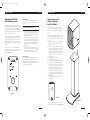
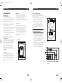
Veritas 'i' OM (E)
5/14/03
2:21 PM
Page 1
WARRANTY
veritas i
™
Limited Warranty Policy
in the United States
and Canada
ENERGY® SPEAKER SYSTEMS warrants this product to
the retail purchaser against any failure resulting from
original manufacturing defects in workmanship or
materials. The warranty is in effect for a period of 5 years
from date of purchase from an authorized ENERGY®
dealer and is valid only if the original dated bill of sale is
presented when service is required.
The warranty does not cover damage caused during
shipment, by accident, misuse, abuse, neglect,
unauthorized product modification, failure to follow the
instructions outlined in the owner’s manual, failure to
perform routine maintenance, damage resulting from
unauthorized repairs or claims based upon
misrepresentations of the warranty by the seller.
Warranty Service
If you require service for your ENERGY® speaker(s) at any
time during the warranty period, please contact:
1) the dealer from whom you purchased the product(s),
2) ENERGY® NATIONAL SERVICE, 203 Eggert Road,
Buffalo, N.Y. 14215 Tel: 716-896-9801
3) ENERGY® SPEAKER SYSTEMS, a division of Audio
Products International Corp., 3641 McNicoll Avenue,
Toronto, Ontario, Canada, M1X 1G5,
Tel: 416-321-1800.
4) Additional service centers can be found by checking
the ENERGY® SPEAKER SYSTEMS website:
www.energy-speakers.com or, by calling either of
the above numbers.
You will be responsible for transporting the speakers in
adequate packaging to protect them from damage in
transit and for the shipping costs to an authorized
ENERGY® service center or to ENERGY® SPEAKER
SYSTEMS. If the product is returned for repair to
ENERGY® SPEAKER SYSTEMS in Toronto or Buffalo, the
costs of the return shipment to you will be paid by
ENERGY®, provided the repairs concerned fall within the
Limited Warranty. The ENERGY® Warranty is limited to
repair or replacement of ENERGY® products. It does not
cover any incidental or consequential damage of any kind.
If the provisions in any advertisement, packing cartons or
literature differ from those specified in this warranty, the
terms of the Limited Warranty prevail.
Warranty Outside of the
United States and Canada
Outside North America, the warranty may be changed to
comply with local regulations. Ask your local ENERGY®
dealer for details of the LIMITED WARRANTY applicable in
your country.
“ENERGY", the “ENERGY” logo, “Veritas", and
“Musical Truth", are trademarks of Audio Products
International Corp.. “Dolby", “Dolby Pro-Logic",
and “Dolby Digital", are trademarks of Dolby
Laboratories Licensing. “DTS” is a trademark of
Digital Theater Systems Inc.
Energy Speaker Systems, a Division of Audio Products International Corp.
3641 McNicoll Avenue, Toronto, Ontario, Canada M1X 1G5
416-321-1800 Fax 416-321-1500 www.energy-speakers.com
Printed in Canada
7AI//ENV21
Printed in Canada
7AI//ENV2I
Veritas 'i' OM (E)
NOTES
5/14/03
2:21 PM
Page 5
Veritas i ™
WELCOME TO MUSICAL TRUTH ™
The new ENERGY® Veritas i™ Series
Congratulations on your purchase of the new Veritas i™
Series speakers from ENERGY® SPEAKER SYSTEMS.
The proprietary technology in the Veritas i™ Series has
been refined by the engineering division in order to
consistently produce groundbreaking results.
In the quest to attain goals set by its predecessors,
Veritas i™ Series adheres to four main design objectives,
and in doing so, reaches a new level of excellence.
1) To preserve the original recorded sound as closely as
possible – Musical Truth™.
2) To reduce distortion to its lowest possible
measurement.
3) To maintain wide and constant dispersion, for superb
stereo imaging and soundstage.
4) To maintain a wide signal bandwidth, even in the
smallest of enclosures.
If you have any problems with the set up of your speakers
you can do one of the following:
1) After reading and understanding this manual, contact
your retailer for assistance. The ENERGY® Veritas™
network of dealers has been trained to help our
customers learn more about the products they have
purchased and to assist in obtaining the ultimate in
performance from them.
2) Contact us via e-mail by way of the ENERGY®
Website. This way we can get back to you quickly
with answers to your questions at your convenience.
(www.energy-speakers.com)
3) Contact us by phone during regular business hours
(8:30–5:00-EST) at 416-321-1800.
We truly believe your new ENERGY® Veritas i™ series
speakers will provide a lifetime of enjoyment and
pleasurable listening experiences!
These goals are strictly adhered to in all stages of
transducer, crossover and enclosure design as well as in
the prototyping, electrical engineering, and all listening
tests. The Veritas i™ Series has been designed from its
conception to musically outperform anything in its price
range. The new technologies realized by the engineering
group have dramatically reduced distortion. New
transducer and baffle designs have realized improvements
in diffraction, which vastly improves the stereo imaging of
a speaker. This new series embodies all that ENERGY®
SPEAKER SYSTEMS has accomplished in our 20+ years of
loudspeaker design and manufacturing.
We hope you will enjoy your speakers for many years,
and that the setup and placement suggestions contained
in this manual will serve to further enhance your
listening pleasure.
14
3
Veritas 'i' OM (E)
5/14/03
2:21 PM
Page 7
OWNERS MANUAL
Veritas i ™
Table of Contents
Safety Concerns
Welcome to Musical Truth™
3
Table of Contents
4
Break in Procedures
5
Set-Up Basics
5
Advanced Set Up
5
Positioning the Front Speakers
Advanced Set Up
6
Placement of the Rear Channel V2.0Ri Speakers
6
Side Position
6
Rear Position
6
Corner Position
6
Proper Usage of the Veritas™ Stand
7
Connection Instructions
8
Traditional Connection Method
8
Bi-Wire Method
8
Bi-Amplification Method
8
Bi-Amplification Wiring Instructions
8
™
Your new Veritas i series speakers should be gently
cleaned with only a damp cloth and warm water from
time to time to remove any dust or fingerprints. Do not
use an abrasive cleaner, or any type of ammonia based
cleaners, or window type cleaners. To remove the dust
from the grill cloth, use the brush attachment on your
vacuum cleaner or a slightly dampened sponge or dust
free cloth.
SPIKED AND RUBBER FEET
The Veritas i™ Series V2.2i bookshelf loudspeakers include
two rubber feet. These are to be attached to the speaker
in the front corners when used with other stands, or if
placed on a bookshelf or other stable surface. The
bumpers are self adhesive and will protect the speaker as
well as the surface it sits on. The rear of the speaker is
supported by the single rest in the middle. See Figure 8.
The V2.3i and V2.4i floor standing models however have
four metal spikes included, with five insert locations. Use
the spikes only on a carpeted surface as they can damage
hardwood floors. You have a choice of using three spikes,
two in the front, one in the rear, or four spikes, one in
each of the speakers' corners. See Figure 9.
NOTE: Use the four spike option if you are
concerned about stability.
After installing the spikes and locating the speaker, do not
move the speaker by any type of dragging motion. It can
not only scratch the floor, but the inserts in the base of the
speaker could be damaged. Always completely lift the
speaker up to relocate its position.
SPIKE INSTALLATION INSTRUCTIONS
To insert the spikes, place the speaker carefully on its side,
and insert the spikes into the desired locations. Then turn
the spike by hand to the right until it is firmly seated. The
spikes can also be used as levelers in case the floor is not
perfectly level. See Figure 9.
2
1
9
Connection of V2.0Ri
9
Bi-Wiring and Bi-Amplification
9
Adjusting the V2.0Ri Rear Channel speaker
CARE OF THE FINISH
6
Placement of the Center Channel V2.0Ci
Connecting the Veritas™ 2.0Ri Rear Channel Surround Speaker
IMPORTANT: Please retain the carton and packing
materials for this ENERGY® Veritas™ product to
protect it in the event you ever need to transport
the unit for any reason. Product received damaged
at a service center that has been shipped by the
end user in other than the original packaging, will
be repaired, refurbished and properly packaged for
return shipment at the end user's expense.
5
Veritas i ™
OWNERS MANUAL
10
Mode Switch
10
Level Control
10
How to Set Up the Controls
11
Specifications
12
Safety Concerns
13
Care of Finish
13
Spiked and Rubber Feet
13
Spike Installation Instructions
13
Limited Warranty Policy in the United States and Canada
14
Warranty Service
14
Warranty Outside of the United States and Canada
14
4
3
5
FIGURE 9
FIGURE 8
4
13
2:21 PM
Page 9
Veritas i ™
Cherry Veneer w/ Black
HG Black w/ Black
Rubber Bumpers
Cherry Veneer w/ Black
HG Black w/ Black
Spike Kit
Rubber Bumpers
Cherry Veneer w/ Black
HG Black w/ Black
High Gloss Black with
Two Colored Reversible Trim Panels
39lbs / 17.5kg
95lbs / 42.7kg
68lbs / 30.6kg
38lbs / 17.1kg (Dual)
H - 8-3/4” / 22.2cm
D - 12-3/4” / 32.3cm
W - 23” / 58.4cm
H - 46” / 116.8cm
D - 17” / 43.1 cm
W - 8-3/4” / 22.2cm
H - 40-1/2” / 102.8cm
D - 13” / 33cm
W - 8-3/4” / 22.2cm
H - 14-1/2” / 36.8cm
D - 7-1/4” / 18.4cm
W - 12-3/8” / 31.4cm
2-6-1/2”
Dual Hyperdrive Woofers
1” Aluminum Dome Tweeter
2-3” Mid-Band Fill Drivers
1-6-1/2”
Dual Hyperdrive Woofer
1” Aluminum Dome Tweeter
1” Aluminum Dome Tweeter
2” Aluminum Dome Midrange
3-6-1/2”
Dual Hyperdrive Woofers
1” Aluminum Dome Tweeter
2” Aluminum Dome Midrange
2-6-1/2”
Dual Hyperdrive Woofers
Tweeter: 1.8kHz and >
Woofer: ~ to 1.8kHz
Mid-Band: 200Hz-10kHz
Tweeter: 2.0kHz and >
Woofer: ~ to 2.0kHz
Tweeter: 2.0kHz and >
Midrange: 550Hz-2.0kHz
Woofer 3: ~ to 550Hz
Woofer 2: ~ to 300Hz
Woofer 1: ~ to 150Hz
1” Aluminum Dome Tweeter
2” Aluminum Dome Midrange
1-6-1/2”
Dual Hyperdrive Woofer
H - 18” / 45.7cm
D - 13” / 33cm
W - 8-3/4” / 22.2cm
69lbs / 31kg (Dual)
Cherry Veneer w/ Black
HG Black w/ Black
2 Silver Cone Isolators
Rubber Bumpers
Components
Dimensions
Shipping Weight
Cabinet Finishes
Accessories
Tweeter: 2.0kHz and >
Midrange: 550Hz-2.0kHz
Woofer: ~ to 550Hz
Operating Range
Tweeter: 2.0kHz and >
Midrange: 550Hz-2.0kHz
Woofer 2: ~ to 550Hz
Woofer 1: ~ to 300Hz
1.8kHz
2.0kHz
300Hz, 550Hz, 2.0kHz
300Hz, 550Hz, 2.0kHz
550Hz, 2.0kHz
Crossover Points
89dB
90dB
(Two speakers in a typical room)
Sensitivity
89dB
90dB
89dB
46 Hz
40 Hz
25 Hz
35 Hz
Usable Base Response
- 10dB (Anechoic Measurement)
29 Hz
70-20,000 Hz
50-20,000 Hz
40-20,000 Hz
Frequency Response
+/- 3dB (Typical Room Response)
35-20,000 Hz
30-20,000 Hz
4 ohm
4 ohm
4 ohm
4 ohm
4 ohm
Minimum Impedance
8 ohm nominal
8 ohm nominal
Impedance
8 ohm nominal
8 ohm nominal
8 ohm nominal
100 watts
150 watts
250 watts
200 watts
150 watts
Recommended
Amplifier Power
Acoustic Suspension
Bass Reflex
Rear Vented
Bass Reflex
Front and Rear Vented
Bass Reflex
Rear Vented
Bass Reflex
Front Vented
V2.0Ci
Center Channel
Speaker System
Specifications
V2.2i
Bookshelf
V2.3i
Floorstanding
V2.4i
Floorstanding
V2.0Ri
Rear Channel
OWNERS MANUAL
Veritas i ™
OWNERS MANUAL
Break in Procedures
Two Reversible
Trim Panels
5/14/03
It is VITAL that your new Veritas i™ Series speakers be
allowed to break In properly before you perform any
precise set up procedures, system adjustments, and before
you play them at higher volume levels.
The best method of performing the break in is to play a
full range musical passage at a moderate level as long as
possible. Utilizing the repeat function on your CD or DVD
player can assist greatly.
the position of the listeners. The ultimate goal, is to
have the rear speakers approximately the same
distance from the listeners as the front speakers. If the
room's layout does not allow for this, then the basic
rule is to place the front and rear speakers in the
room so that they form a square or rectangle around
the listeners. More details are found ahead.
Advanced Set Up
POSITIONING THE FRONT SPEAKERS
Optimum sound will not be achieved until approximately
100 hours of playing time. After break-in, the volume level
can be increased. Do not play the speakers at higher
levels until the break in process has been completed. The
transducers need to “loosen up”, and until this occurs,
damage can result to the transducers.
The placement of the front speakers in relation to the
listener is absolutely critical. The perfect set up would
place the listener at the end of a triangle, with the
distance from speaker to listener being 1.5 times the width
between the two speakers. The minimum distance
between the speakers is 6-8 feet, any less and the stereo
imaging will be quite poor.
Set-Up Basics
The optimum room shape would be a rectangular room,
with the speakers along the short wall, facing towards the
other short wall. Placement in corners, and against a wall
is not recommended. Try to keep the speakers, especially
rear vented models a minimum of 2 feet from the back
wall, and corner placement is usually the worst of all
possible places to put a speaker.
There are three basic steps in the successful installation
of the system.
1) Decide where you wish to place the speakers
2) Connect the speakers
3) Adjust the controls where necessary
The most vital part of the set up procedure to realize the
goal of getting the best sound your room, and equipment
has to offer, is proper placement of the speakers. Please
wait until the speakers are fully broken in before
experimenting with precise speaker placement. There are
a few do's and don't's with regards to speaker placement.
1) With regards to the front speakers, try not to place
them too close or too far apart. The “1.5 times the
width” rule applies, and is required for good stereo
imaging from the front speakers. See the Advanced
Set Up section for details.
2) The center channel speaker needs to be centrally
located so that the dialog appears to be coming from
the center of the TV or Screen. See the Advanced Set
Up section for details.
3) The rear channel Veritas™ 2.0Ri are quite flexible with
regards to placement, but still require care when
choosing the placement. Study your room carefully
and decide whether the side walls are best, or the
rear walls. The goal is to try to position the speaker
system around you, so that you are “surrounded” by
the information from the different channels. The
choice of rear speaker placement depends greatly on
Spike Kit
Rubber Bumpers
Veritas 'i' OM (E)
12
The ENERGY® design philosophy of Wide and Constant
Dispersion provides a wide image, and clarity off axis from
the speaker. For best results, utilize the side walls of the
room to enhance the size and depth of the image.
See Figure 1A.
FIGURE 1A
5
Veritas 'i' OM (E)
5/14/03
2:22 PM
Page 11
Veritas i ™
OWNERS MANUAL
Advanced Set Up
PLACEMENT OF THE
CENTER CHANNEL V2.0Ci
The center channel needs to be placed either above or
below the TV monitor, but as close to the TV as possible.
The center channel carries dialogue information which
should sound like it is emanating from the center of the
TV. If using a Rear Projection Television, then above is
probably your only choice. If you have a front projection
system, than you have alternate choices of either stand
mounting, or placement on furniture, etc.
When deciding on the center channel speaker placement,
it is important to place the speaker so that the edge of the
speakers' front is at the edge of the shelf or stand
supporting it. Unwanted diffraction would occur if the
center channel is situated too far back into a cabinet or
other surface with edges that could impede the dispersion
of the speaker. See Figure 1B.
REAR POSITION
HOW TO SET UP THE CONTROLS
The rear wall can also be used for placement of the rear
V2.0Ri speakers. The optimum placement would be on
either side of the listening area, but not in the corners of
the room. Experimentation with the “SoundField
Management” System will yield many different results.
Refer to the separate section for adjusting the “SoundField
Management” System.
The following chart (Diagram “B”) will explain how to set
up the controls on the Soundfield Management System.
But follow these instructions first.
1) The first thing you must do is measure two distances.
First measure the distance between the listening
position and one of the front speakers (D1 on
Diagram “A”), then measure the distance between
the listening position and the rear speakers, (D2 on
Diagram “A”). Subtract the two measurements, and
the resulting number is the difference. The bottom
scale of the chart shows the difference in distance.
See Diagram “A” for assistance, and Diagram “B” for
the actual chart.
CORNER POSITION
If you are limited to a corner placement of the rear
channel speakers, we have designed a special “SoundField
Management” mode for this purpose. It will turn off the
side firing mid-fill driver above the control panel. Please
notice that the two rear channel speakers are mirrorimaged of each other. When mounting the speakers, be
sure to put the control panel facing the corner. This way
the corner facing mid driver will not emanate sound. The
other mid driver which faces out into the room, will
produce sound.
2)
3)
Front Speakers
V2.2i, V2.3i, V2.4i
Locate the measured difference on the bottom scale
of the graph (Diagram “B”), then follow the line up
to where it intersects with the horizontal line and
look to the left scale to see the level control setting
recommendation. The grayed section shows when
the Switch should be in Bi-Polar Mode, and the rest
of the chart shows the Di-Polar Mode as the
selected mode.
Always experiment with the controls, and adjust them
to your liking, the chart will give you a good starting
point, but each room is different, and depending on
the V2.0Ri’s location, furniture placement and
materials in the room, adjustments may be necessary.
Rear Speakers
V2.ORi
DIAGRAM A
CENTER
CHANNEL
SUBWOOFER
LEFT
SIDE POSITION
RIGHT
SIDE POSITION
REAR OR CORNER POSITION
LEFT MAIN
The optimal side placement for the V2.0Ri would be
beside the listening area, a few feet behind the couch, at
a height approximately 2/3 of the wall height from the
floor. The “SoundField Management” System can be
adjusted in many different ways. Refer to the separate
section for adjusting the “SoundField Management”
System.
FIGURE 1B
RIGHT MAIN
SIDE POSITION
Center Channel
V2.OCi
Note: We do not recommend having the distance
between the listener and the rear speakers to be
greater than the front measurement.
PLACEMENT OF THE REAR CHANNEL
V2.0Ri SPEAKERS
The Rear Channel V2.0Ri speakers are optimally placed on
either the sides of your listening area, or the rear walls.
The V2.0Ri has been designed with installation flexibility as
its key goal. The side firing mid-fill transducers coupled
with the front firing woofer and tweeter combine to
produce various levels and effects depending on the
speakers' location, and how the “SoundField
Management” System is adjusted. The following are
suggestions of where you can place your V2.0Ri speakers.
See Figure 1B.
Veritas i ™
OWNERS MANUAL
DIAGRAM B
6
11
Veritas 'i' OM (E)
5/14/03
2:22 PM
Page 13
Veritas i ™
OWNERS MANUAL
Adjusting the V2.0Ri
Rear Channel speaker
The exclusive and patented “Soundfield Management”
System allows adjustment of the surround field in different
room environments, to compensate for different direct to
reflected sound ratios. The controls permit adjustment of
the soundfield type, and the relative level of the side firing
drivers compared to the front drivers.
In a perfect world, all of the 5 speakers in a home theater
would be the same distance from the listener. But when
trying to implement a system into your room environment,
this isn't always possible. The direct to reflected sound
ratio is what allows the ear to judge distance and depth of
the sound.
There are two controls on the “Soundfield Management”
Control panel which is located behind the speaker grill on
either the left or right side. The speakers are mirror
imaged. See Figure 7.
Proper Usage of the
Veritas™ Stand for
the V2.2i Model
MODE SWITCH
The first control is the 3-Position Mode Switch. It allows
you to customize the type of soundfield the speaker will
produce.
Note: Regardless of the switches' position, the two
front drivers are always functioning.
1)
2)
3)
Veritas i ™
OWNERS MANUAL
The Veritas™ Stand has been purpose built not only
to improve the looks of the Veritas™ bookshelf model
V2.2i, but also to place the speakers at the optimum
height.
In the “Corner” Position, one of the two side firing
drivers are disengaged. The side-firing driver above
the control panel is disengaged, while the other side
firing driver remains active.
In the “Bi-pole” position the two side firing drivers are
engaged and are operating in phase with each other.
The resulting sound field is more expansive, and with
correct placement, the sound will reflect off of room
boundaries to create a large and expansive sounding
surround field.
In the “Di-pole” position the side drivers are active, but
are wired out of phase from each other. The resulting
sound field is even more expansive, and can create
an even larger effect than the bi-pole mode.
The Veritas™ speakers incorporate inserts into the speakers'
bottom, to allow physically attaching the speaker to the
stand for enhanced safety. Please follow the instructions in
this order.
1) Begin assembly of the stand, one by one, carefully
following the directions included in the stands'
packaging.
2) Decide if you wish to use filler material in the stands
before you complete the assembly process. Filler will
not only add weight to the stand, but mass, which
helps provide a solid foundation for the speaker. As
well, filler material helps eliminate resonances that can
transfer to the floor and “color” the resulting sound
from the speaker.
3) Complete the assembly of both stands.
4) Place the speaker on the stand.
5) Using the hardware supplied with the stand, attach
the speaker to it by inserting the two Philips head
bolts from the bottom of the stands' top plate into the
insert on the speakers' bottom. Hand tighten only!
6) The front bolt goes through the front hole on the
top plate, inserted from the bottom. Insert the bolt
into the speaker, the insert is situated in the middle
of the speakers' base. The second bolt inserts into
the semi-circular rear foot on the back of the speaker.
See Figure 2A.
7) Once both are in place, tighten them both with a
Philips screwdriver.
LEVEL CONTROL
The Level Control adjusts the relative output of the side
firing drivers compared to the front drivers. At the
maximum setting they are approximately 1 dB lower in
volume than the front drivers. The minimum setting turns
the side firing drivers completely off.
FIGURE 7
FIGURE 2A
FIGURE 2B
The speaker is now attached providing better stability,
better sound, and of course great looks! See Figure 2B.
10
7
Veritas 'i' OM (E)
5/14/03
2:22 PM
Page 15
Veritas i ™
OWNERS MANUAL
Connection Instructions
™
The Connections for the Veritas i Series speakers are quite
similar to any standard speaker with bi-wire/ bi-amp
options. There are 4 Gold Plated Connectors on the rear
of the speaker enclosure, and although they look unique,
they are traditional in function.
1)
TRADITIONAL
CONNECTION METHOD
1)
2)
Using your choice of bare wire, banana-type jacks, or
spade lugs, connect the speaker cable (minding the
positive and negative polarities), to the lower set of
connectors. Ensure the terminals are tight.
Repeat the procedure for the second speaker.
See Figure 3.
NOTE: Please ensure the positive and negative
terminals on the speaker match the positive and
negative terminals on the amplifier. Reversing these
will cause an abnormal sound, and a total
reduction of bass frequencies under normal
listening conditions.
2)
NOTE: Before starting, remove the gold straps,
which connect the top and bottom set of terminals.
To remove the straps, loosen the connectors, pull
the straps up, and then towards you through the
large hole. Make sure you put them in a safe place
for future use.
2)
3)
–
+
–
+
This method involves using 2-channels of amplification,
with multiple cables and connectors, to access both sets
of terminals on the Veritas™ Loudspeakers. The benefit of
bi-wiring is to reduce noise, and reduce the likelihood of
grounding problems, as you will have twice the thickness
of cable between the amp and speakers as the traditional
method would provide. For more details on the benefits
of bi-wiring, please discuss this with your authorized
ENERGY® retailer.
+
NOTE: The four connectors on the V2.0Ri speaker
differ slightly from the other models.
PLEASE READ THIS SECTION CAREFULLY.
FIGURE 3
BI-WIRE METHOD
–
Connecting the Veritas™
2.0Ri Rear Channel
Surround Speaker
NOTE: Before starting, remove the gold straps,
which connect the top and bottom set of terminals.
To remove the straps, loosen the connectors, pull
the straps up, and then towards you through the
large hole. Make you sure you put them in a safe
place for future use.
1)
+
FIGURE 5
BI-AMPLIFICATION WIRING INSTRUCTIONS
–
1.
2.
Please ensure the gold straps are in place between
the upper and lower terminals before starting. Using
your choice of bare wire, banana-type jacks, or spade
lugs, connect the speaker cable from the amplifier
(minding the positive and negative polarities), to the
lower set of connectors. Ensure the terminals are
tight.
Repeat the procedure for the other rear channel
speaker. See Figure 6.
+
–
This connection system involves the use of two separate
amplifiers to power one set of speakers. The idea is to
have one stereo amplifier connected to one speaker, and
another identical amplifier powering the second speaker.
This is often referred to as “Vertical” Bi-amplification. It is
the only method ENERGY® recommends.
+
CONNECTION OF V2.0Ri
FIGURE 4
BI-AMPLIFICATION METHOD
–
Next, connect the second cable, from the amplifiers
other channel to the lower set of terminals again
ensuring a tight connection.
Repeat Steps 1 and 2 for the second loudspeaker
using the second amplifier. See Figure 5.
NOTE: Notice the upper and lower terminals
accept the wire from a different angle, this is to
simplify the connection process by making access
easier, and to improve cosmetics by allowing easier
“dressing” of the cables.
Using your choice of bare wire,
banana-type jacks, or spade lugs,
connect one speaker cable from
the amplifier (minding the
positive and negative polarities)
to the top set of connectors.
Ensure the terminals are tight.
Next, connect the second cable,
from the amplifier (same channel,
secondary connectors) to the
lower set of terminals on the
Veritas™ speaker. See Figure 4.
NOTE: Notice the upper and
lower terminals accept the wire
from a different angle, this is to
simplify the connection process
by making access easier, and to
improve cosmetics by allowing
easier “dressing” of the cables.
Veritas i ™
OWNERS MANUAL
Using your choice of bare wire, banana-type jacks, or
spade lugs, connect one speaker cable from the
amplifier (minding the positive and negative polarities)
to the top set of connectors. Ensure the terminals
are tight.
Under normal circumstances, you will never have the
need to bi-wire, or bi-amplify the rear channel speakers in
a typical home theater system. If you are unsure, in the
meantime you may choose to connect them using the
Standard Connection Method described below. Ask your
authorized ENERGY® Veritas™ dealer if there are any
questions about your systems' particular needs.
8
–
+
–
+
FIGURE 6
BI-WIRING AND BI-AMPLIFICATION
If you wish to bi-wire, or bi-amplify the V2.0Ri Rear
Channel speakers, you may do so, however the terminals
on the back are slightly different from the terminals found
on the other models. The same four connectors are
present, the difference being the type of connector, and
the shape and type of gold-strap used to connect the
upper and lower set of terminals. Refer to the Connection
Instructions for Bi-Wiring, and Bi-Amplification for details
on how to wire in this manner.
NOTE: To remove the straps from the V2.ORi,
loosen the gold terminals, and pull the strap out to
the right. It should easily fall out of place. Make
sure you put them in a safe place for future use.
9
Veritas 'i' OM (E)
5/14/03
2:22 PM
Page 13
Veritas i ™
OWNERS MANUAL
Adjusting the V2.0Ri
Rear Channel speaker
The exclusive and patented “Soundfield Management”
System allows adjustment of the surround field in different
room environments, to compensate for different direct to
reflected sound ratios. The controls permit adjustment of
the soundfield type, and the relative level of the side firing
drivers compared to the front drivers.
In a perfect world, all of the 5 speakers in a home theater
would be the same distance from the listener. But when
trying to implement a system into your room environment,
this isn't always possible. The direct to reflected sound
ratio is what allows the ear to judge distance and depth of
the sound.
There are two controls on the “Soundfield Management”
Control panel which is located behind the speaker grill on
either the left or right side. The speakers are mirror
imaged. See Figure 7.
Proper Usage of the
Veritas™ Stand for
the V2.2i Model
MODE SWITCH
The first control is the 3-Position Mode Switch. It allows
you to customize the type of soundfield the speaker will
produce.
Note: Regardless of the switches' position, the two
front drivers are always functioning.
1)
2)
3)
Veritas i ™
OWNERS MANUAL
The Veritas™ Stand has been purpose built not only
to improve the looks of the Veritas™ bookshelf model
V2.2i, but also to place the speakers at the optimum
height.
In the “Corner” Position, one of the two side firing
drivers are disengaged. The side-firing driver above
the control panel is disengaged, while the other side
firing driver remains active.
In the “Bi-pole” position the two side firing drivers are
engaged and are operating in phase with each other.
The resulting sound field is more expansive, and with
correct placement, the sound will reflect off of room
boundaries to create a large and expansive sounding
surround field.
In the “Di-pole” position the side drivers are active, but
are wired out of phase from each other. The resulting
sound field is even more expansive, and can create
an even larger effect than the bi-pole mode.
The Veritas™ speakers incorporate inserts into the speakers'
bottom, to allow physically attaching the speaker to the
stand for enhanced safety. Please follow the instructions in
this order.
1) Begin assembly of the stand, one by one, carefully
following the directions included in the stands'
packaging.
2) Decide if you wish to use filler material in the stands
before you complete the assembly process. Filler will
not only add weight to the stand, but mass, which
helps provide a solid foundation for the speaker. As
well, filler material helps eliminate resonances that can
transfer to the floor and “color” the resulting sound
from the speaker.
3) Complete the assembly of both stands.
4) Place the speaker on the stand.
5) Using the hardware supplied with the stand, attach
the speaker to it by inserting the two Philips head
bolts from the bottom of the stands' top plate into the
insert on the speakers' bottom. Hand tighten only!
6) The front bolt goes through the front hole on the
top plate, inserted from the bottom. Insert the bolt
into the speaker, the insert is situated in the middle
of the speakers' base. The second bolt inserts into
the semi-circular rear foot on the back of the speaker.
See Figure 2A.
7) Once both are in place, tighten them both with a
Philips screwdriver.
LEVEL CONTROL
The Level Control adjusts the relative output of the side
firing drivers compared to the front drivers. At the
maximum setting they are approximately 1 dB lower in
volume than the front drivers. The minimum setting turns
the side firing drivers completely off.
FIGURE 7
FIGURE 2A
FIGURE 2B
The speaker is now attached providing better stability,
better sound, and of course great looks! See Figure 2B.
10
7
Veritas 'i' OM (E)
5/14/03
2:22 PM
Page 11
Veritas i ™
OWNERS MANUAL
Advanced Set Up
PLACEMENT OF THE
CENTER CHANNEL V2.0Ci
The center channel needs to be placed either above or
below the TV monitor, but as close to the TV as possible.
The center channel carries dialogue information which
should sound like it is emanating from the center of the
TV. If using a Rear Projection Television, then above is
probably your only choice. If you have a front projection
system, than you have alternate choices of either stand
mounting, or placement on furniture, etc.
When deciding on the center channel speaker placement,
it is important to place the speaker so that the edge of the
speakers' front is at the edge of the shelf or stand
supporting it. Unwanted diffraction would occur if the
center channel is situated too far back into a cabinet or
other surface with edges that could impede the dispersion
of the speaker. See Figure 1B.
REAR POSITION
HOW TO SET UP THE CONTROLS
The rear wall can also be used for placement of the rear
V2.0Ri speakers. The optimum placement would be on
either side of the listening area, but not in the corners of
the room. Experimentation with the “SoundField
Management” System will yield many different results.
Refer to the separate section for adjusting the “SoundField
Management” System.
The following chart (Diagram “B”) will explain how to set
up the controls on the Soundfield Management System.
But follow these instructions first.
1) The first thing you must do is measure two distances.
First measure the distance between the listening
position and one of the front speakers (D1 on
Diagram “A”), then measure the distance between
the listening position and the rear speakers, (D2 on
Diagram “A”). Subtract the two measurements, and
the resulting number is the difference. The bottom
scale of the chart shows the difference in distance.
See Diagram “A” for assistance, and Diagram “B” for
the actual chart.
CORNER POSITION
If you are limited to a corner placement of the rear
channel speakers, we have designed a special “SoundField
Management” mode for this purpose. It will turn off the
side firing mid-fill driver above the control panel. Please
notice that the two rear channel speakers are mirrorimaged of each other. When mounting the speakers, be
sure to put the control panel facing the corner. This way
the corner facing mid driver will not emanate sound. The
other mid driver which faces out into the room, will
produce sound.
2)
3)
Front Speakers
V2.2i, V2.3i, V2.4i
Locate the measured difference on the bottom scale
of the graph (Diagram “B”), then follow the line up
to where it intersects with the horizontal line and
look to the left scale to see the level control setting
recommendation. The grayed section shows when
the Switch should be in Bi-Polar Mode, and the rest
of the chart shows the Di-Polar Mode as the
selected mode.
Always experiment with the controls, and adjust them
to your liking, the chart will give you a good starting
point, but each room is different, and depending on
the V2.0Ri’s location, furniture placement and
materials in the room, adjustments may be necessary.
Rear Speakers
V2.ORi
DIAGRAM A
CENTER
CHANNEL
SUBWOOFER
LEFT
SIDE POSITION
RIGHT
SIDE POSITION
REAR OR CORNER POSITION
LEFT MAIN
The optimal side placement for the V2.0Ri would be
beside the listening area, a few feet behind the couch, at
a height approximately 2/3 of the wall height from the
floor. The “SoundField Management” System can be
adjusted in many different ways. Refer to the separate
section for adjusting the “SoundField Management”
System.
FIGURE 1B
RIGHT MAIN
SIDE POSITION
Center Channel
V2.OCi
Note: We do not recommend having the distance
between the listener and the rear speakers to be
greater than the front measurement.
PLACEMENT OF THE REAR CHANNEL
V2.0Ri SPEAKERS
The Rear Channel V2.0Ri speakers are optimally placed on
either the sides of your listening area, or the rear walls.
The V2.0Ri has been designed with installation flexibility as
its key goal. The side firing mid-fill transducers coupled
with the front firing woofer and tweeter combine to
produce various levels and effects depending on the
speakers' location, and how the “SoundField
Management” System is adjusted. The following are
suggestions of where you can place your V2.0Ri speakers.
See Figure 1B.
Veritas i ™
OWNERS MANUAL
DIAGRAM B
6
11
2:21 PM
Page 9
Veritas i ™
Cherry Veneer w/ Black
HG Black w/ Black
Rubber Bumpers
Cherry Veneer w/ Black
HG Black w/ Black
Spike Kit
Rubber Bumpers
Cherry Veneer w/ Black
HG Black w/ Black
High Gloss Black with
Two Colored Reversible Trim Panels
39lbs / 17.5kg
95lbs / 42.7kg
68lbs / 30.6kg
38lbs / 17.1kg (Dual)
H - 8-3/4” / 22.2cm
D - 12-3/4” / 32.3cm
W - 23” / 58.4cm
H - 46” / 116.8cm
D - 17” / 43.1 cm
W - 8-3/4” / 22.2cm
H - 40-1/2” / 102.8cm
D - 13” / 33cm
W - 8-3/4” / 22.2cm
H - 14-1/2” / 36.8cm
D - 7-1/4” / 18.4cm
W - 12-3/8” / 31.4cm
2-6-1/2”
Dual Hyperdrive Woofers
1” Aluminum Dome Tweeter
2-3” Mid-Band Fill Drivers
1-6-1/2”
Dual Hyperdrive Woofer
1” Aluminum Dome Tweeter
1” Aluminum Dome Tweeter
2” Aluminum Dome Midrange
3-6-1/2”
Dual Hyperdrive Woofers
1” Aluminum Dome Tweeter
2” Aluminum Dome Midrange
2-6-1/2”
Dual Hyperdrive Woofers
Tweeter: 1.8kHz and >
Woofer: ~ to 1.8kHz
Mid-Band: 200Hz-10kHz
Tweeter: 2.0kHz and >
Woofer: ~ to 2.0kHz
Tweeter: 2.0kHz and >
Midrange: 550Hz-2.0kHz
Woofer 3: ~ to 550Hz
Woofer 2: ~ to 300Hz
Woofer 1: ~ to 150Hz
1” Aluminum Dome Tweeter
2” Aluminum Dome Midrange
1-6-1/2”
Dual Hyperdrive Woofer
H - 18” / 45.7cm
D - 13” / 33cm
W - 8-3/4” / 22.2cm
69lbs / 31kg (Dual)
Cherry Veneer w/ Black
HG Black w/ Black
2 Silver Cone Isolators
Rubber Bumpers
Components
Dimensions
Shipping Weight
Cabinet Finishes
Accessories
Tweeter: 2.0kHz and >
Midrange: 550Hz-2.0kHz
Woofer: ~ to 550Hz
Operating Range
Tweeter: 2.0kHz and >
Midrange: 550Hz-2.0kHz
Woofer 2: ~ to 550Hz
Woofer 1: ~ to 300Hz
1.8kHz
2.0kHz
300Hz, 550Hz, 2.0kHz
300Hz, 550Hz, 2.0kHz
550Hz, 2.0kHz
Crossover Points
89dB
90dB
(Two speakers in a typical room)
Sensitivity
89dB
90dB
89dB
46 Hz
40 Hz
25 Hz
35 Hz
Usable Base Response
- 10dB (Anechoic Measurement)
29 Hz
70-20,000 Hz
50-20,000 Hz
40-20,000 Hz
Frequency Response
+/- 3dB (Typical Room Response)
35-20,000 Hz
30-20,000 Hz
4 ohm
4 ohm
4 ohm
4 ohm
4 ohm
Minimum Impedance
8 ohm nominal
8 ohm nominal
Impedance
8 ohm nominal
8 ohm nominal
8 ohm nominal
100 watts
150 watts
250 watts
200 watts
150 watts
Recommended
Amplifier Power
Acoustic Suspension
Bass Reflex
Rear Vented
Bass Reflex
Front and Rear Vented
Bass Reflex
Rear Vented
Bass Reflex
Front Vented
V2.0Ci
Center Channel
Speaker System
Specifications
V2.2i
Bookshelf
V2.3i
Floorstanding
V2.4i
Floorstanding
V2.0Ri
Rear Channel
OWNERS MANUAL
Veritas i ™
OWNERS MANUAL
Break in Procedures
Two Reversible
Trim Panels
5/14/03
It is VITAL that your new Veritas i™ Series speakers be
allowed to break In properly before you perform any
precise set up procedures, system adjustments, and before
you play them at higher volume levels.
The best method of performing the break in is to play a
full range musical passage at a moderate level as long as
possible. Utilizing the repeat function on your CD or DVD
player can assist greatly.
the position of the listeners. The ultimate goal, is to
have the rear speakers approximately the same
distance from the listeners as the front speakers. If the
room's layout does not allow for this, then the basic
rule is to place the front and rear speakers in the
room so that they form a square or rectangle around
the listeners. More details are found ahead.
Advanced Set Up
POSITIONING THE FRONT SPEAKERS
Optimum sound will not be achieved until approximately
100 hours of playing time. After break-in, the volume level
can be increased. Do not play the speakers at higher
levels until the break in process has been completed. The
transducers need to “loosen up”, and until this occurs,
damage can result to the transducers.
The placement of the front speakers in relation to the
listener is absolutely critical. The perfect set up would
place the listener at the end of a triangle, with the
distance from speaker to listener being 1.5 times the width
between the two speakers. The minimum distance
between the speakers is 6-8 feet, any less and the stereo
imaging will be quite poor.
Set-Up Basics
The optimum room shape would be a rectangular room,
with the speakers along the short wall, facing towards the
other short wall. Placement in corners, and against a wall
is not recommended. Try to keep the speakers, especially
rear vented models a minimum of 2 feet from the back
wall, and corner placement is usually the worst of all
possible places to put a speaker.
There are three basic steps in the successful installation
of the system.
1) Decide where you wish to place the speakers
2) Connect the speakers
3) Adjust the controls where necessary
The most vital part of the set up procedure to realize the
goal of getting the best sound your room, and equipment
has to offer, is proper placement of the speakers. Please
wait until the speakers are fully broken in before
experimenting with precise speaker placement. There are
a few do's and don't's with regards to speaker placement.
1) With regards to the front speakers, try not to place
them too close or too far apart. The “1.5 times the
width” rule applies, and is required for good stereo
imaging from the front speakers. See the Advanced
Set Up section for details.
2) The center channel speaker needs to be centrally
located so that the dialog appears to be coming from
the center of the TV or Screen. See the Advanced Set
Up section for details.
3) The rear channel Veritas™ 2.0Ri are quite flexible with
regards to placement, but still require care when
choosing the placement. Study your room carefully
and decide whether the side walls are best, or the
rear walls. The goal is to try to position the speaker
system around you, so that you are “surrounded” by
the information from the different channels. The
choice of rear speaker placement depends greatly on
Spike Kit
Rubber Bumpers
Veritas 'i' OM (E)
12
The ENERGY® design philosophy of Wide and Constant
Dispersion provides a wide image, and clarity off axis from
the speaker. For best results, utilize the side walls of the
room to enhance the size and depth of the image.
See Figure 1A.
FIGURE 1A
5
Veritas 'i' OM (E)
5/14/03
2:21 PM
Page 7
OWNERS MANUAL
Veritas i ™
Table of Contents
Safety Concerns
Welcome to Musical Truth™
3
Table of Contents
4
Break in Procedures
5
Set-Up Basics
5
Advanced Set Up
5
Positioning the Front Speakers
Advanced Set Up
6
Placement of the Rear Channel V2.0Ri Speakers
6
Side Position
6
Rear Position
6
Corner Position
6
Proper Usage of the Veritas™ Stand
7
Connection Instructions
8
Traditional Connection Method
8
Bi-Wire Method
8
Bi-Amplification Method
8
Bi-Amplification Wiring Instructions
8
™
Your new Veritas i series speakers should be gently
cleaned with only a damp cloth and warm water from
time to time to remove any dust or fingerprints. Do not
use an abrasive cleaner, or any type of ammonia based
cleaners, or window type cleaners. To remove the dust
from the grill cloth, use the brush attachment on your
vacuum cleaner or a slightly dampened sponge or dust
free cloth.
SPIKED AND RUBBER FEET
The Veritas i™ Series V2.2i bookshelf loudspeakers include
two rubber feet. These are to be attached to the speaker
in the front corners when used with other stands, or if
placed on a bookshelf or other stable surface. The
bumpers are self adhesive and will protect the speaker as
well as the surface it sits on. The rear of the speaker is
supported by the single rest in the middle. See Figure 8.
The V2.3i and V2.4i floor standing models however have
four metal spikes included, with five insert locations. Use
the spikes only on a carpeted surface as they can damage
hardwood floors. You have a choice of using three spikes,
two in the front, one in the rear, or four spikes, one in
each of the speakers' corners. See Figure 9.
NOTE: Use the four spike option if you are
concerned about stability.
After installing the spikes and locating the speaker, do not
move the speaker by any type of dragging motion. It can
not only scratch the floor, but the inserts in the base of the
speaker could be damaged. Always completely lift the
speaker up to relocate its position.
SPIKE INSTALLATION INSTRUCTIONS
To insert the spikes, place the speaker carefully on its side,
and insert the spikes into the desired locations. Then turn
the spike by hand to the right until it is firmly seated. The
spikes can also be used as levelers in case the floor is not
perfectly level. See Figure 9.
2
1
9
Connection of V2.0Ri
9
Bi-Wiring and Bi-Amplification
9
Adjusting the V2.0Ri Rear Channel speaker
CARE OF THE FINISH
6
Placement of the Center Channel V2.0Ci
Connecting the Veritas™ 2.0Ri Rear Channel Surround Speaker
IMPORTANT: Please retain the carton and packing
materials for this ENERGY® Veritas™ product to
protect it in the event you ever need to transport
the unit for any reason. Product received damaged
at a service center that has been shipped by the
end user in other than the original packaging, will
be repaired, refurbished and properly packaged for
return shipment at the end user's expense.
5
Veritas i ™
OWNERS MANUAL
10
Mode Switch
10
Level Control
10
How to Set Up the Controls
11
Specifications
12
Safety Concerns
13
Care of Finish
13
Spiked and Rubber Feet
13
Spike Installation Instructions
13
Limited Warranty Policy in the United States and Canada
14
Warranty Service
14
Warranty Outside of the United States and Canada
14
4
3
5
FIGURE 9
FIGURE 8
4
13
Veritas 'i' OM (E)
NOTES
5/14/03
2:21 PM
Page 5
Veritas i ™
WELCOME TO MUSICAL TRUTH ™
The new ENERGY® Veritas i™ Series
Congratulations on your purchase of the new Veritas i™
Series speakers from ENERGY® SPEAKER SYSTEMS.
The proprietary technology in the Veritas i™ Series has
been refined by the engineering division in order to
consistently produce groundbreaking results.
In the quest to attain goals set by its predecessors,
Veritas i™ Series adheres to four main design objectives,
and in doing so, reaches a new level of excellence.
1) To preserve the original recorded sound as closely as
possible – Musical Truth™.
2) To reduce distortion to its lowest possible
measurement.
3) To maintain wide and constant dispersion, for superb
stereo imaging and soundstage.
4) To maintain a wide signal bandwidth, even in the
smallest of enclosures.
If you have any problems with the set up of your speakers
you can do one of the following:
1) After reading and understanding this manual, contact
your retailer for assistance. The ENERGY® Veritas™
network of dealers has been trained to help our
customers learn more about the products they have
purchased and to assist in obtaining the ultimate in
performance from them.
2) Contact us via e-mail by way of the ENERGY®
Website. This way we can get back to you quickly
with answers to your questions at your convenience.
(www.energy-speakers.com)
3) Contact us by phone during regular business hours
(8:30–5:00-EST) at 416-321-1800.
We truly believe your new ENERGY® Veritas i™ series
speakers will provide a lifetime of enjoyment and
pleasurable listening experiences!
These goals are strictly adhered to in all stages of
transducer, crossover and enclosure design as well as in
the prototyping, electrical engineering, and all listening
tests. The Veritas i™ Series has been designed from its
conception to musically outperform anything in its price
range. The new technologies realized by the engineering
group have dramatically reduced distortion. New
transducer and baffle designs have realized improvements
in diffraction, which vastly improves the stereo imaging of
a speaker. This new series embodies all that ENERGY®
SPEAKER SYSTEMS has accomplished in our 20+ years of
loudspeaker design and manufacturing.
We hope you will enjoy your speakers for many years,
and that the setup and placement suggestions contained
in this manual will serve to further enhance your
listening pleasure.
14
3
Veritas 'i' OM (E)
5/14/03
2:21 PM
Page 1
WARRANTY
veritas i
™
Limited Warranty Policy
in the United States
and Canada
ENERGY® SPEAKER SYSTEMS warrants this product to
the retail purchaser against any failure resulting from
original manufacturing defects in workmanship or
materials. The warranty is in effect for a period of 5 years
from date of purchase from an authorized ENERGY®
dealer and is valid only if the original dated bill of sale is
presented when service is required.
The warranty does not cover damage caused during
shipment, by accident, misuse, abuse, neglect,
unauthorized product modification, failure to follow the
instructions outlined in the owner’s manual, failure to
perform routine maintenance, damage resulting from
unauthorized repairs or claims based upon
misrepresentations of the warranty by the seller.
Warranty Service
If you require service for your ENERGY® speaker(s) at any
time during the warranty period, please contact:
1) the dealer from whom you purchased the product(s),
2) ENERGY® NATIONAL SERVICE, 203 Eggert Road,
Buffalo, N.Y. 14215 Tel: 716-896-9801
3) ENERGY® SPEAKER SYSTEMS, a division of Audio
Products International Corp., 3641 McNicoll Avenue,
Toronto, Ontario, Canada, M1X 1G5,
Tel: 416-321-1800.
4) Additional service centers can be found by checking
the ENERGY® SPEAKER SYSTEMS website:
www.energy-speakers.com or, by calling either of
the above numbers.
You will be responsible for transporting the speakers in
adequate packaging to protect them from damage in
transit and for the shipping costs to an authorized
ENERGY® service center or to ENERGY® SPEAKER
SYSTEMS. If the product is returned for repair to
ENERGY® SPEAKER SYSTEMS in Toronto or Buffalo, the
costs of the return shipment to you will be paid by
ENERGY®, provided the repairs concerned fall within the
Limited Warranty. The ENERGY® Warranty is limited to
repair or replacement of ENERGY® products. It does not
cover any incidental or consequential damage of any kind.
If the provisions in any advertisement, packing cartons or
literature differ from those specified in this warranty, the
terms of the Limited Warranty prevail.
Warranty Outside of the
United States and Canada
Outside North America, the warranty may be changed to
comply with local regulations. Ask your local ENERGY®
dealer for details of the LIMITED WARRANTY applicable in
your country.
“ENERGY", the “ENERGY” logo, “Veritas", and
“Musical Truth", are trademarks of Audio Products
International Corp.. “Dolby", “Dolby Pro-Logic",
and “Dolby Digital", are trademarks of Dolby
Laboratories Licensing. “DTS” is a trademark of
Digital Theater Systems Inc.
Energy Speaker Systems, a Division of Audio Products International Corp.
3641 McNicoll Avenue, Toronto, Ontario, Canada M1X 1G5
416-321-1800 Fax 416-321-1500 www.energy-speakers.com
Printed in Canada
7AI//ENV21
Printed in Canada
7AI//ENV2I


![13.56MHz [MIFARE] Contactless Smart Card](http://vs1.manualzilla.com/store/data/005689074_1-1b5ba2b7f854420e24ee51932ec4423a-150x150.png)
