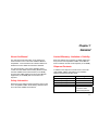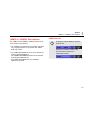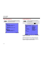
1
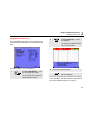
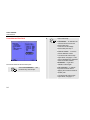
®
Fluke199XRAY
Medical ScopeMeter
Users Manual
4822 872 30791
August 2006
© 2006 Fluke Corporation, All rights reserved.
All product names are trademarks of their respective companies.
Table of Contents
Title
About this Manual...........................................................................................................
Safety Information ..........................................................................................................
Limited Warranty, Limitation of Liability ..........................................................................
Shipment Contents.........................................................................................................
About the X-RAY kVp Function ......................................................................................
190B/C vs. 199XRAY User Interface..............................................................................
USER Button Bar.......................................................................................................
190B/C RECORDER Key ..........................................................................................
199XRAY MEDICAL Key...........................................................................................
kVp Measurement Procedure.........................................................................................
Selecting a Filter Pack....................................................................................................
Wide Range – Low Range Filter Pack.......................................................................
CT & Mobile Pack Plus Filter Pack ............................................................................
Cadmium K-edge Mammo Filter Pack Calibration Overview.....................................
k-Edge Mammo Filter Pack .......................................................................................
Linear Mammo Filter Pack.........................................................................................
kVp Scope Mode ............................................................................................................
Radiographic Mode (RADIO).....................................................................................
i
Page
1-1
1-1
1-1
1-1
1-2
1-3
1-3
1-4
1-4
2-1
2-1
2-2
2-2
2-3
2-5
2-6
2-7
2-7
Fluke199XRAY
Users Manual
Fluoro Mode (FLUORO)............................................................................................
kV Measurements .....................................................................................................
Exposure Time Measurements (RADIO only) ...........................................................
AUTO-kVp Mode, MANUAL Mode ...........................................................................
Selecting AUTO-kVp mode – Manual Mode.........................................................
Auto kVp Mode Waveform Requirements ............................................................
kVp Scope Mode Screen, Readings, F1-F4 Keys .....................................................
kVp Mode Readings .............................................................................................
F1…F4 Softkey Functions ....................................................................................
kVp Scope Mode Presets..........................................................................................
Specifications.................................................................................................................
ii
2-7
2-7
2-8
2-9
2-9
2-9
2-10
2-10
2-11
2-12
2-16
Chapter 1
General
About this Manual
Limited Warranty, Limitation of Liability
This manual provides information on the X-RAY kVp
measurement function of the Fluke 199XRAY Medical
ScopeMeter. It also describes user interface differences
between the Fluke 190B/C and the Fluke 199XRAY.
Read the Warranty and Limitation of Liability statements
that you find in the ScopeMeter 190B/C Users Manual
that is included in the test tool kit shipment (on CD ROM).
For other information on the Fluke 199XRAY please
consult the Fluke 190B/C Series Getting Started manual,
the Fluke 190B/C Series Users Manual (on CD-ROM),
and the Fluke 190B/C Medical Functions Users Manual
Supplement (on CD-ROM) that are included in the
shipment.
Safety Information
Read and comply with the safety instructions that you find
in the ScopeMeter 190B/C Series Getting Started manual
and in the Fluke 190B/C Users Manual .
Shipment Contents
In addition to the shipment contents shown in the Fluke
192B-196B/C-199B/C Users Manual, the 199XRAY
shipment includes the following parts:
Part
Power Adapter Plug UK
Power Adapter Plug EURO
Power Adapter Plug Australia
Power Adapter Plug USA
MA190 Accessory Set
Ordering code
2726493
2726507
2726518
2726529
See 190B/C Medical
Functions Users
Manual Supplement.
1-1
Fluke 199XRAY
Users Manual
About the X-RAY kVp Function
The 199XRAY Medical Scopemeter, when used with Fluke
Biomedical kVp Divider, automatically measure kVp
average and kV peak. In the radiographic measurement
mode, exposure time is also measured in milliseconds or
pulses.
The Fluke Biomedical Non-Invasive kVp Divider (Model
35080/A/B/M) is an alternative to high-voltage divider
tanks. It provides safe, non-invasive, fast measurement of
kVp without endangering personnel and/or equipment. Its
use is primarily intended for X-ray machine service and
calibration. The kVp Divider provides an analog output
voltage proportional to the instantaneous voltage applied
to the X-ray tube.
1-2
The X-RAY kVp function provides oscilloscope setups for
measurements using the kVp Divider and the following
filter packs on Input A :
•
•
•
•
•
•
Wide Range Filter Pack
K-edge Mammo Filter Pack
Linear Mammo Filter Pack
CT Filter Pack
Mobile Pack Plus Filter Pack
Low Range Filter Pack
For details on the kVp Divider refer to the 35080/A/B/M
Operators Manual.
General
190B/C vs. 199XRAY User Interface
190B/C vs. 199XRAY User Interface
The 190B/C and the 199XRAY operating instructions are
equal, except for the following:
• The 199XRAY user interface text is available in English
only, language selection is not possible. See ‘USER
Button Bar ’ below.
• The 190B/C RECORDER functions can be selected by
pressing the RECORDER key.
The 199XRAY RECORDER functions can be selected
by pressing the MEDICAL key.
See ‘190B/C RECORDER Key’ and ‘199XRAY
MEDICAL Key’ below.
1
USER Button Bar
Pressing the 190B/C USER key will open
the button bar:
Pressing the 199XRAY USER key will
open the button bar without the
LANGUAGE selection:
1-3
Fluke 199XRAY
Users Manual
190B/C RECORDER Key
Pressing the RECORDER key will open
the screen shown below.
199XRAY MEDICAL Key
Pressing the MEDICAL key will open
the screen below.
Press again or press
to exit.
The Medical measurements kVp function is described in
Chapter 2 of this manual.
Operating instructions for the Scope-Trend Plot, the
Scope- Scope Record , and for the Meter-Trend Plot
mode are described in the Fluke190B/C User Manual
Chapter 3 Using the Recorder Functions.
1-4
Chapter 2
Using the X-RAY kVp Function
kVp Measurement Procedure
Selecting a Filter Pack
To perform kVp measurements, do the following:
To select a filter pack, do the following:
1
Follow the operating instructions for the filter
pack as described in the filter pack Operators
Manual.
Connect the kVp divider to Input A of the
199XRAY using a shielded 1:1 cable, for
example the cable of the MA190 Accessory set.
2
Select the required filter pack, see ‘Selecting a
Filter Pack’.
3
Start the measurement. See kVp Scope Mode
on page 2-7 for further instructions.
1
Display the
MEDICAL/RECORDER screen.
2
Select ■ kVp with the arrow keys,
then accept with the F4 (ENTER)
key. One of the Filter Pack
Selection Screens will be shown.
2-1
Fluke 199XRAY
Users Manual
Wide Range – Low Range Filter Pack
CT & Mobile Pack Plus Filter Pack
Similar screens are shown for Wide Range and Low
Range.
Similar screens are shown for Wide Range and Low
Range.
Proceed as follows to select the filter pack:
Proceed as follows to select the filter pack:
1
Select ■ Wide Range or ■ Low
Range with the arrow keys, then
accept.
2
Select the wanted signal shape,
then accept.
The test tool will enter the kVp
Scope Mode, see page 2-7.
2-2
1
Select ■ CT or ■ Mobile Pack
Plus with the arrow keys, then
accept.
The test tool will enter the kVp
Scope Mode, see page 2-7.
Using the X-RAY kVp Function
Selecting a Filter Pack
Cadmium K-edge Mammo Filter Pack Calibration
Overview
During Cadmium K-edge Mammo Filter Pack calibration,
screen instructions will guide you through the calibration
steps. This section provides an explanation of the
calibration steps.
Read the mammographic filter pack sections of the Model
35080/A/B/M kVp Divider Instruction Manual to become
familiar with the specifications, theory of operation, and
application of corrections for these filter packs.
K-edge Measurement Setup:
Install the Cadmium K-edge Filter Pack in the kVp Divider.
Place the kVp divider in the x-ray beam on the
compression paddle or other suitable support with the long
axis of the kVp divider perpendicular to the axis of the xray tube. Raise the kVp divider as close as possible to the
x-ray tube. The x-ray beam should cover the entire filter
pack. Select the k-Edge Mammo filter pack from the filter
pack menu.
2
25 kVp Measurement Procedure:
Set the x-ray generator for 25 kVp, 100 mA, 80 ms. If not
available, use a mAs setting that provides an exposure of
80 ms (+/- 10 ms). Select the molybdenum (Mo) filter on
the generator. Make the first baseline measurement.
26 kVp Measurement Procedure:
Repeat the baseline measurement at a slightly higher kV
setting that should still be below the k-edge (26.7 kV). Set
the generator for 26 kVp,100 mA, 80 ms. If not available,
use a mAs setting that provides an exposure of 80 ms (+/10 ms).
If the voltage difference between the first and second
baseline measurements is within the limits (+/- 20mV), this
is the baseline voltage. If the voltage difference is outside
the limits, repeat the above measurements at 24 kVp and
25 kVp respectively.
29kVp Measurement Procedure:
Set the generator for 29 kVp,100 mA, 80 ms. If not
available, use a mAs setting that provides an exposure of
80 ms (+/- 10 ms). Make the k-edge kV reference
measurement.
2-3
Fluke 199XRAY
Users Manual
If the exposure is within the range 27.5 to 29.5 kVp, the
reading is accurate. If ---.kVp is displayed, set the
generator for 28 kVp and repeat step 4. If 0.0 kVp is
displayed, set the generator to 30 kVp and repeat step 4.
The k-edge kVp is used to determine linear filter pack
correction.
Once an accurate determination of kVp has been made do
not disturb the x-ray generator settings. Proceed to linear
mammo filter pack use.
Linear Measurement Setup:
Remove the k-edge filter pack and replace it with the
linear mammo filter pack. Increase the target to filter pack
distance to about 15 inches (38cm). If the Model
35080/A/B/M kVp Divider changes position in the x or y
axis with respect to the x-ray generator during the linear
kVp measurements, you must repeat the determination of
the k-edge kVp and the correction value since this
measurement is position sensitive.
2-4
Linear Correction Exposure:
Make an exposure using the same generator settings as
those used to make the last k-edge exposure. After this
measurement is complete, the kV correction for the linear
filter pack will be displayed. If you do not want your linear
kVp measurements automatically corrected, press F1
(LINEAR CHANGE…) and select No Correction. To
recalibrate the k-edge correction, select Recalibrate…
2
Using the X-RAY kVp Function
Selecting a Filter Pack
k-Edge Mammo Filter Pack
2
The k-Edge Mammo filter pack is used to determine the
correction factor (recalibrate) for the Linear Mammo filter
pack.
Proceed as follows to do the recalibration:
1
Select ■ k-Edge Mammo… with
the arrow keys, then accept.
The screen will show the present
k-Edge calibration values.
Accept ■ Recalibrate… to start
the calibration.
You will see the calibration startup
screen as shown below.
3
4
Follow the screen instructions.
Close the instruction banner and
start the calibration.
You will be guided through the calibration procedure by
screen messages. See also ‘Cadmium K-edge Mammo
Filter Pack Calibration Overview’ on page 2-3
2-5
Fluke 199XRAY
Users Manual
Linear Mammo Filter Pack
2
Select and accept:
■ Recalibrate… to determine the
correction factor for the linear
Mammo filter pack.
Continue as for the k-Edge
Mammo filter pack step 3.
■ Use cal. values… to use the
present calibration values.
Proceed as follows to select the filter pack:
1
Select ■ Linear Mammo… with
the arrow keys, then accept.
The test tool will enter the kVp
Scope Mode, see page 2-7. This
choice is disabled if the calibration
values are invalid. Select ■
Recalibrate… to get valid
calibration values again.
■ No correction… to perform
kVp measurements without
applying the correction factors for
the filter pack.
The test tool will enter the kVp
Scope Mode, see page 2-7.
2-6
Using the X-RAY kVp Function
kVp Scope Mode
2
kVp Scope Mode
Fluoro Mode (FLUORO)
When entering the kVp Scope mode predefined scope
settings for the selected filter pack are provided. Some of
these settings are fixed, some can be manually adjusted.
See kVp Scope Mode Presets on page 2-12.
When used in the Fluoro mode, the 199XRAY waits for a
trigger then samples the kV waveform at one sample per
second. For each sample, kVp-avg and kV-peak are
measured (each sample must also meet the Automatic
kVp Mode requirements). Each sample is stored in the
instrument’s replay buffer and up to 100 samples can be
stored. When the fluoro exposure stops or if the replay
buffer fills, the Replay Menu is displayed and each sample
may be displayed using the F1, F2, and F3 keys. To start
a new measurement, press F4, EXIT REPLAY.
There are two different measurement modes in the kVp
Scope Mode, the RADIO mode for measuring single
radiographic exposures and the FLUORO mode for
measuring continuous or pulsed fluoroscopic exposures.
Radiographic Mode (RADIO)
When used in the Radiographic mode, the 199XRAY waits
for a trigger then stores the entire kV waveform. When the
radiographic exposure is complete, kVp-avg, kV-peak, and
exposure time in ms or pulses displayed (the kV waveform
must also meet the Automatic kVp Mode requirements).
The instrument is then ready for another exposure.
Note:
The most recent 100 screens are always stored
in the replay buffer. To view stored screens,
press the REPLAY button and use the F1, F2,
and F3 keys. To start a new measurement, press
F4, EXIT REPLAY. For more information, please
see the 190B/C Users Manual.
kV Measurements
kVp average is the average value of the kV peaks within
the measurement area and is indicated by the tick marks
on the vertical cursors.
kV Peak is the highest kV value within the measurement
area.
In radiographic (RADIO) mode, the kV measurement area
is the central 80% of the kV waveform; the first and last
10% of the waveform are excluded from these
measurements.
In fluoroscopic (FLUORO) mode, kV is measured over the
complete waveform sample.
2-7
Fluke 199XRAY
Users Manual
Note:
When measuring kV, the bottom of the trace
(indicated by the A input zero icon “A-“ at the left
of the screen) is not zero. The value at the
bottom of the trace is the zero value for the
selected filter pack. Table 2-1, Default Filter Pack
Settings, lists the zero values for all filter packs.
For example, when using the Wide Range Filter
Pack the zero value is 40 kV. If the kV waveform
is 3 divisions above zero and the vertical
sensitivity is 20 kV/div (60 kV), the measured kV
is 100 kV (40 kV + 60 kV = 100 kV). For more
information, see the 35080/A/B/M User Manual.
These adjustments are automatically performed
for all kV measurements.
AUTO-kVp Mode, MANUAL Mode
In the AUTO-kVp mode, vertical cursor lines are
automatically positioned to indicate the area used for the
kVp measurement (10…90% area).
In the MANUAL mode you can select between horizontal
and vertical cursors, and you can manually move the
cursors. The cursors allow you to make precise digital
measurements on the waveform manually.
Selecting AUTO-kVp mode – Manual Mode
Do the following to select AUTO-kVp or Manual mode:
Select AUTO-kVp or MANUAL mode.
The right top corner of the screen shows
AUTO-kVp or MANUAL.
Exposure Time Measurements (RADIO only)
Exposure time in milliseconds is measured between the
points corresponding to 75% of kVp-avg on the first rising
edge and last falling edge of the kV waveform.
To operate the cursors you can turn the cursor menu on:
Exposure time in pulses is measured by counting the
pulses that exceed 75% of kVp-avg during the exposure.
F1…F4 key labels for cursor menu OFF:
Turn cursor menu OFF or ON.
F1…F4 key labels for cursor menu ON:
2-8
Using the X-RAY kVp Function
kVp Scope Mode
Auto kVp Mode Waveform Requirements
For automatic measurement of kV in the Fluoroscopic
measurement mode, the waveform must be onscreen and
must meet the following criteria:
• The kV being measured must be within the range of the
chosen filter pack and must be above the trigger level
for the filter pack and sensitivity setting (See Tables 2-1
and 2-2).
• The vertical height of the entire waveform must be
greater than 2.5 divisions above the zero level
• No portion of the waveform may be off the top of the
screen
2
For automatic measurement of kV and exposure time in
the radiographic measurement mode, the entire waveform
must be onscreen and must meet the following criteria:
• The kV being measured must be within the range of the
chosen filter pack and must be above the trigger level
for the filter pack and sensitivity setting (See Tables 2-1
and 2-2).
• The vertical height of the entire waveform must be
greater than 2.5 divisions above the zero level
• No portions of the waveform may be offscreen
• The last falling edge of the waveform must be greater
than 3.5 divisions horizontally from the rising edge
(trigger position).
• The last falling edge of the waveform must be less than
9 divisions from the rising edge (trigger position). This
leaves the last horizontal division with a signal at zero
level, which verifies that the current acquisition contains
the complete signal.
2-9
Fluke 199XRAY
Users Manual
kVp Scope Mode Screen, Readings, F1-F4 Keys
An example of the kVp scope mode screen is shown in the
figure below. Numerical readings and the softkey button
bar differ from the normal Scope mode.
In the MANUAL mode other readings may be shown
depending on the selected cursors. See ‘F1…F4 softkey
functions for cursor menu ON’ on the next page.
TIME/PULSE# Readings:
You can select Time or Pulse readings, if applicable, using
the F3 key.
kVp Mode Readings
Voltage readings:
xxx.x kVp - avg
average kVp value between cursors,
indicated by the tick marks on the
vertical cursors
xxx.x kV - peak
kV peak value between cursors
2-10
xx.xx ms
time of pulse (AUTO)
xx.xx ms
time of multiple pulses (AUTO)
xxx pls
number of pulses (AUTO)
xx.xx ms
time between cursors (MANUAL)
xxx pls
number of pulses between cursors
(MANUAL)
Note: If the kV or exposure time values cannot be
calculated because of the signal shape, or because
the kV is not within the range of the chosen filter
pack, dashes will be displayed. Use the Manual
mode to read the voltage at each cursor position or
adjust the vertical and/or horizontal sensitivity to
obtain a signal that meets the Auto kVp Mode
Waveform Requirements.
2
Using the X-RAY kVp Function
kVp Scope Mode
F1…F4 Softkey Functions
F1…F4 softkey functions for cursor menu OFF:
The key label shows the current filter pack
name.
Press to return to the Filter pack selection
screen if you want to select another filter pack.
Select optimal scope settings for RADIO or
FLUORO mode measurements (if applicable).
Select between TIME (in ms) or PULSE#
reading in the RADIO mode. PULSE# is not
available when HF/Three Phase signal shape
is selected.
Exit the kVp mode and return to the
MEDICAL/RECORDER screen.
F1…F4 softkey functions for cursor menu ON:
Select the cursor mode:
AUTO-kVp mode
MANUAL mode: Two vertical cursors. Use
to move the cursors. Use F2 to select
cursor to be moved.
kVp measurements apply to the area between
the cursors.
MANUAL mode: two horizontal cursors. Use
to move the cursors. Use F2 to
select cursor to be moved.
Readings are:
- voltage difference between cursors (A ↕)
- voltage at the upper (HIGH) and lower
(LOW) cursor position
MANUAL MODE: One vertical cursor. Use
to move the cursor.
Readings are:
- the average, minimum, and maximum
voltage at the cursor position
Select the cursor to be moved.
Select between TIME or PULSE# reading.
Exit the MANUAL mode and return to the
AUTO kVp mode.
2-11
Fluke 199XRAY
Users Manual
Sensitivity, Probe Factor, and Bandwidth filter are
fixed.
kVp Scope Mode Presets
When entering the kVp mode some Scope functions are
preset. Some of these function setting are fixed, some can
be changed. See Table 2-1 and Table 2-2 for details.
Note:
In kVp mode Input B can be used , but will show
no readings. A trace will only be shown if
triggering via Input A occurs.
Trigger settings can not be changed.
Vertical defection can be changed using the RANGE
key.
Time base can be changed using the TIME key. The
highest time base speed is 500 μs/div.
Table 2-1. Default Filter Pack Settings
Filter Pack
Wide Range
K-Edge Mammo
Linear Mammo
CT
Mobile Pack Plus
Low Range
2-12
Vertical Sensitivity
20 kV/div
500 mV/div
5 kV/div
20 kV/div
20 kV/div
20 kV/div
Zero Value
40 kV
0V
0 kV
60 kV
40 kV
26 kV
Horizontal Deflection
10 ms/div
10 ms/div
10 ms/div
10 ms/div
10 ms/div
10 ms/div
Trigger Level
80 kV
1V
10 kV
100 kV
80 kV
46 kV
Using the X-RAY kVp Function
kVp Scope Mode
2
Table 2-2. kV Range and Trigger Level vs. Filter Pack and Vertical Sensitivity
Filter Pack
Wide Range
K-Edge Mammo
Linear Mammo
CT
Mobile Pack Plus
Low Range
Vertical Sensitivity
kV Range
Trigger Level
20 kV/div *
10 kV/div
5 kV/div
500 mV/div*
5 kV/div *
10 kV/div
80 -150 kV
60 – 100 kV
50 – 70 kV
N/A
10 – 30 kV
20 – 40 kV
80 kV
60 kV
50 kV
1V
10 kV
20 kV
20 kV/div*
10 kV/div
5 kV/div
20 kV/div*
10 kV/div
5 kV/div
10 kV/div*
5 kV/div
2 kV/div
100 – 140 kV
80 -120 kV
70 – 90 kV
80 – 135 kV
60 – 100 kV
50 – 70 kV
46 – 90 kV
36 – 60 kV
30 – 40 kV
100 kV
80 kV
70 kV
80 kV
60 kV
50 kV
46 kV
36 kV
30 kV
* Default settings.
2-13
Fluke 199XRAY
Users Manual
Specifications
The 199XRAY kVp Measurement Accuracy Specifications
are shown in table 2-3.
Table 2-3. 199XRAY kVp Measurement Accurcy Specifications
Filter Pack
kVp-Avg Accuracy
Large Signal
kV Peak Accuracy*
Exposure Time Accuracy
Small Signal
Wide-Range
1%
1.5%
2%
0.5%
K-Edge Mammo
1%
N/A
N/A
0.5%
Linear Mammo
1%
1.5%
2%
0.5%
CT
1%
1.5%
2%
0.5%
Mobile Pack Plus**
1%
2%
2%
0.5%
Low Range
1%
1.5%
2%
0.5%
* The kV peak measurement accuracy may be affected by measurement system noise and waveform artifacts.
**Maximum error with 100% ripple
2-14