1
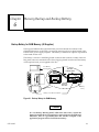
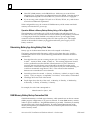
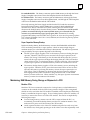
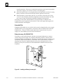
This Datasheet is for the
IC693ACC301
Backup Battery for RAM Memory
http://www.qualitrol.com/shop/p-14537-ic693acc301.aspx
Provides the wiring diagrams and installation guidelines for this GE Series 90-30
module.
For further information, please contact Qualitrol Technical Support at
1-800-784-9385
[email protected]
Chapter Memory Backup and Backup Battery
6
Backup Battery for RAM Memory (All Supplies)
The long-life Lithium battery (IC693ACC301) used to maintain the contents of the
CMOS RAM memory in the CPU is accessed by removing the cover plate located at the
bottom of the power supply faceplate. This battery is mounted on a plastic clip attached
to the inside of this cover.
The battery is wired to a small Berg female connector that connects to either of the two
Berg male connectors mounted on the Power Supply printed circuit board. This battery
can be replaced with power applied to the PLC.
a43833
PWR
OK
RUN
BATT
Low Battery
Warning LED
ÎÎÎ
ÎÎ
ÎÎÎ
ÎÎ
ÎÎÎ
ÎÎ
ÎÎÎ
ÎÎÎ
ÎÎÎÎÎÎ
ÎÎ
ÎÎÎÎÎÎ
ÎÎ
ÎÎÎÎÎÎ
B
A
T
T
E
R
Y
BATTERY
CONNECTORS
ÎÎÎ
LITHIUM
BACK-UP
BATTERY
Battery
Cavity
Battery Cover Removal Notch
Figure 6-1. Backup Battery for RAM Memory
Caution
If a Low Battery Warning (BATT LED turns ON) occurs, replace the
battery located in the power supplybefore removing power from the rack.
Otherwise, there is a possibility that data will be corrupted or the
application program will be cleared from memory.
GFK-0356P
6-1
6
Battery Replacement Instructions
Warning
To avoid the chance of losing the contents of RAM memory, you can
carefully perform the following steps with PLC power ON. This
procedure should only be performed by qualified electrical personnel
who are trained in applicable electrical safety rules and procedures.
Failure to follow standard electrical safety practice can result in injury
or death to personnel, damage to equipment, or both.
6-2
H
Carefully insert the tip a small pocket-size screwdriver approximately 1/4 inch (6
mm) into the battery cover removal slot, located beneath the battery cover (see
previous figure).
H
H
Gently rotate the screwdriver about 45 degrees to loosen the cover.
H
Carefully reach into battery cavity with your fingers (do not use a metal object to do
this) and unplug the battery connector.
H
Remove the old battery from the clip on the battery cover and set it aside. Be careful
not to mix it up with the new battery.
H
Carefully reach into battery cavity with your fingers (do not use a metal object to do
this) and plug in new battery connector.
H
H
Clip new battery into clip on battery cover.
Remove cover with fingers. The battery is mounted in a clip on the back of the
cover. It has a pair of leads with a connector that is plugged-in to a connector on a
circuit board inside the power supply.
Snap battery cover back onto power supply.
Series 90-30 PLC Installation and Hardware Manual – October 1999
GFK-0356P
6
Battery Replacement/Memor y Protection Factors
Since there are differences in each PLC application, each user will have to determine on
an individual basis what strategy to use. There are several factors to consider when
planning a batteryreplacement/memory protection strategy:
H
How critical is the application? Will considerable loss be sustained if the PLC goes
down? If so, frequent replacement of the battery would be a wise choice. For critical
applications, the cost of a battery would be quite low in comparison to the cost of a
PLC shut-down.
H
How readily can a backup program be loaded? Are there technicians on-site who
know how to load a backup program? Is the backup program accessible at all times
to those responsible for maintaining the equipment? Is a personal computer or
equivalent equipped with GE Fanuc programming software available at all times for
use in loading the backup program?
H
Do you have a preventive maintenance program? A formal program would help
ensure that the battery is replaced on time. Some users replace the backup battery
each year during their annual shut-down period.
H
How accessible is the PLC? In some applications, the PLC may be mounted in a
remote location that is not easily accessed.
H
Safety codes. Some users may have safety rules that would not allow replacing the
battery with power applied.
H
How is the PLC used? Is power left on all the time, or is it shut down every day? See
the heading ”Factors Affecting Battery Life.”
H
Some users run without a backup battery by using one of the PROM options. See
the section below called ”Operating Without a Memory Backup Battery” to
determine if this strategy is suitable for your application.
The Importance of Backing up your Program
Experience has shown that regardless of what strategy you use to maintain PLC
memory, you should, additionally, always keep an up-to-date backup copy of your
application program. The effort required to create and maintain a backup copy is very
small compared to the work required to reprogram, or re-key from hardcopy, your entire
application if, due to some misfortune, it was lost. Other suggestions to help minimize
down time:
GFK-0356P
H
H
Make sure the backup copy is readily accessible to those who may need to use it.
H
Ensure that a suitable computer (usually a laptop type) is equipped with GE Fanuc
PLC programming software and will be readily available to load the backup
program to the PLC.
H
Create a written backup procedure. Fortunately, restoring your program from the
backup copy is probably not something you will do very often. As a result, however,
some of the steps could easily be forgotten.
Train more than one person to load the backup program in case that one person is
not available when needed. Information on creating a backup can be found in GE
Fanuc ’s software user’s manuals. This procedure is also covered in applicable GE
Fanuc programming software training courses.
Chapter 6 Memory Backup and Backup Battery
6-3
6
Factors Affecting Battery Life
Replacing your battery once per year is a good rule of thumb. However, no one can
predict precisely how long a backup battery will last because this depends upon what
CPU is used, what temperature it is subjected to, and how it used. Considering the
following list of factors that affect battery life will help you decide how frequently to
replace the battery in your application:
H
A battery that is not in use has an estimated life (called its ”shelf life”) of 5 years at
”room temperature” (25 degrees C, or 77 degrees F).
H
A battery that is used continuously (supplying current to memory circuits with PLC
power off) has an average estimated life of one year for CPU models 331 and above,
and 2 years for CPU models 311, 313 and 323, if used at room temperature.
H
As long as a PLC is powered up, its battery is not being used; so how often you
power down your PLC has a direct affect on battery life. Some users keep their PLC
powered up all of the time while others turn theirs off every night.
H
Temperature has a relatively large affect on battery life. Temperatures considerably
above room temperature (25 degrees C, or 77 degrees F), or below freezing (0
degrees C, or 32 degrees F) will appreciably shorten battery life.
H
The type of CPU has a small affect on battery life. Some CPUs have more memory
than others. Also, some CPUs have a clock and some do not. More memory
requires more battery current to maintain its contents; and a clock requires battery
current to maintain its operation.
Low Battery Warning Methods
There are three basic ways that the PLC warns of a low battery:
H
The red ”BATT” LED on the Power Supply module lights when the battery is low.
The disadvantage of this method is that the PLC is often mounted in an enclosure,
so this LED might not be easily seen.
H
The PLC Fault Table is updated with a battery low message. Viewing the PLC Fault
Table requires that a programmer be connected to the PLC.
H
Certain System Reference bits are set to logic 1 when the battery is low. These are
%SA011 (LOW_BAT), %SC009 (ANY_FLT), %S010 (SY_FLT), and %SC012
(SY_PRES). The most specific is %SA011 (LOW_BAT). This bit could be used as a
contact in your ladder logic program to turn on an output that controls a warning
light on an operator panel (as in the example rung below), or to send a warning to
an operator interface terminal.
%SA011
%Qxxx
In the rung shown above, the %SA011 contact will close when a low battery is detected
by the PLC. This will turn on the %Q output coil, which addresses an output module’s
output that will turn on a warning light. An alternate method would be to
communicate the status of the coil (which, in that case, would probably be a %M coil) to
a Human to Machine Interface (HMI) terminal such as a GE Fanuc CIMPLICITY HMI
unit. The HMI could be programmed to display a warning message when that
6-4
Series 90-30 PLC Installation and Hardware Manual – October 1999
GFK-0356P
6
particular bit goes to a logic 1. For more information about System Reference bits and
ladder logic programming, see the the Series 90-30/20/Micro PLC CPU Instruction Set
Reference Manual, GFK-0467.
Operating Without a Memory Backup Battery
Whether it would be to your advantage to use a battery-less scheme depends on your
application. There are various advantages and disadvantages to consider in making
your decision.
Possible Advantage
The obvious advantage of operating without a memory backup battery is that you are
freed from the need to maintain the battery. To be able to run without a battery, you
need to have a PROM device – either an EPROM, EEPROM, or Flash PROM – installed
in your system. These devices can store program logic, configuration, and register
values without the need for a backup battery, and you can configure your CPU to read
the contents of PROM into RAM memory each time the PLC is powered up.
Possible Disadvantages
Information is not stored to your PROM device automatically. To store information, you
must stop the PLC, then use a programming device to tell the CPU to write the current
PLC (RAM) memory contents to the PROM device. This requirement may make
battery-less operation undesirable for many users. For example, in many applications,
important data is gathered and stored in RAM register memory, data such as the current
level of material in a tank that is being filled, or a running count of parts produced, etc.
This constantly changing data is not being copied automatically to the PROM device. It
only exists in RAM memory. Therefore, if power is lost and there is no RAM memory
backup battery, this data will be lost.
However, one way to preserve data in a battery-less system is to send it over a network
to a computer that can store the data on its hard drive. Also, static data (data that
doesn’t change) contained in RAM memory, such as mathematical constants or look-up
table type information, can be stored initially in PROM and automatically written back
to RAM each time the PLC powers up.
Another consideration is that if you change your program (or configuration), someone
will have to remember to write the changed information to the PROM device. If that
step is forgotten, then the change only exists in RAM memory, and in a battery-less
system, it will be lost the next time power is removed from the PLC.
Configuring a Battery-Less System
Here are the basic steps to configure a system to run battery-less:
GFK-0356P
H
Equip your CPU with a PROM device. On some CPUs a PROM device is purchased
as an option; on others, it is a standard feature. The CPU chapter of this manual has
a table that identifies the standard PROM configuration for each CPU.
H
There are three CPU configuration parameters involved. Configure them as
follows: Pwr Up Mode: RUN; Logic/Cfg: PROM; Registers: PROM.
H
Store your folder (include Program Logic, Configuration, and Register Data) to the
PLC. This places your entire folder into RAM (working) memory.
Chapter 6 Memory Backup and Backup Battery
6-5
6
H
Write PLC (RAM) memory to the PROM device. Make sure you write all data
(Program Logic, Configuration, and Register Data) to the PROM. Note that the type
of PROM device depends on what model CPU you have and how it is equipped.
H
If you are using a 340 or higher CPU (such as a CPU350, CPU351, etc.), read the next
section for an additional requirement.
When configured this way, the contents of PROM memory will be written into RAM
memory each time the PLC powers up.
Operation Without a Memory Backup Battery Using a 340 or Higher CPU
This information is applicable only to CPU model numbers 340 and higher (such as
CPU350, CPU351, etc.). In systems that do not use a memory backup battery, a standard
0.1” Berg jumper should be installed across either of the two power supply battery
connectors to ensure reliable restarting of the CPU after a power cycle. This jumper
should not be installed if a battery is plugged into either the power supply or CPU
battery connector.
Determining Battery Age Using Battery Date Code
Battery age can be determined from the date code stamped on the battery.
The battery, manufactured by Panasonic, will have a four-digit date code. It will be
something like 5615 or 7Y34. Use the following information to determine the date of
manufacture.
D
First digit shows the year in a rotating 10-year cycle. For example, 0=1990, 1=1991,
2=1992 ... 9=1999, 0=2000, 1=2001, 2=2002, etc. This seeming duplication should
not be a problem because the shelf life of these batteries is 5 years. Batteries in
inventory that are older than 4 years old should be discarded according to the
manufacturer ’s instructions (since they have less than one year of life remaining we
would not recommend using them in a PLC). This will ensure that outdated
batteries are not mistaken for newer batteries.
D
Second digit shows the month. 1=January, 2=February, 3=March, 4=April, 5=May,
6=June, 7=July, 8=August, 9=September, O=October, Y=November, Z=December.
D
D
Third digit shows the week of the month.
Fourth digit shows the day of the week. 1=Monday, 2=Tuesday, 3=Wednesday,
4=Thursday , 5=Friday, 6=Saturday, 7=Sunday.
For example, the code 7612 is interpreted as:
Manufactured on June 3, 1997
RAM Memory Battery Backup Connection Path
CMOS RAM memory is a volatile type of memory, which means that it can lose its contents
(ladder program, configuration, etc.) if power is removed. To retain RAM memory contents
under no-power conditions, a long-life lithium battery is provided. This battery is normally
mounted in the rack’s Power Supply module. To avoid accidental disconnection of the
memory backup battery, it is beneficial to know the connection path between the battery
and the memory circuits:
6-6
Series 90-30 PLC Installation and Hardware Manual – October 1999
GFK-0356P
6
For embedded CPUs: The battery connection path to RAM memory is through the Power
Supply’s baseplate connector and across the backplane board to the RAM circuits.
For modular CPUs: The battery connection path to RAM memory is through the Power
Supply’s baseplate connector, across the backplane board, and through the CPUs baseplate
connector to the RAM circuits inside the CPU module.
Obviously, removing the Power Supply module from the PLC breaks the connection
between the backup battery and the RAM memory circuits for both embedded and
modular CPUs. Also, in a modular CPU system, removing the CPU module would
disconnect the backup battery from the memory circuits. In addition, to avoid the possible
problems associated with losing the contents of RAM memory, we recommend that you
maintain an up-to-date backup copy of your program folder. Instructions for creating
program folder backups can be found in the Logicmaster 90, Series 90-30 Programming Software
User’s Manual, GFK-0466, Control User’s Guide, GFK-1295, and VersaPro Programming Software
User’s Guide, GFK-1670.
Super Capacitor Memory Backup
Besides the backup battery, the RAM memory circuits in both Embedded and Modular
CPUs are further protected by a ”super capacitor,” which can store enough charge to
maintain memory for a short time if the battery is disconnected. The amount of protection
time provided by the super capacitor depends on the following:
D
The PLC power supply supplies 5 VDC to the memory circuits, including the super
capacitor. Therefore, when PLC power is turned off, the super capacitor has an
initial 5 VDC charge. If the battery is also disconnected shortly after PLC power is
turned off, the super capacitor will begin discharging from the 5 VDC level until its
charge reaches 2 VDC, at which time memory contents will be lost. When used this
way, the super capacitor can maintain memory contents for a minimum of 1 hour.
D
The memory backup battery supplies 3 VDC to the memory circuits, including the
super capacitor. Therefore, if PLC power has been turned off for an hour or more
and only the battery is powering the memory circuits, the super capacitor has a 3
VDC charge. Then, if the battery is disconnected, the super capacitor will begin
discharging from the 3VDC level until its charge reaches 2 VDC, at which time
memory contents will be lost. When used this way, the super capacitor can maintain
memory contents for a minimum of 20 minutes.
Maintaining RAM Memory During Storage or Shipment of a CPU
Modular CPUs
Modular CPUs have an internal connector for a backup battery so that RAM memory
contents can be retained while the CPU is being stored or shipped. This arrangement
should not to be used when the CPU module is installed in the baseplate and the backup
battery is installed in the power supply. To use a backup battery in the CPU module, it is
necessary to remove the front cover of the CPU module. This can be accomplished by
following these steps:
GFK-0356P
D
To avoid losing memory contents once the CPU is removed from the PLC, we
recommend you install the backup battery into the CPU within 20 minutes. First,
make sure PLC power is off, then remove the CPU module.
D
Gently squeeze the front cover of the CPU module and pull it forward, away from
the module case, while gently pressing in on the 4 front cover tabs sequentially with
Chapter 6 Memory Backup and Backup Battery
6-7
6
a small screwdriver. The front cover tabs latch into holes on each side of the module
case (refer to Figure 2-1 for location of front cover holding tabs).
D
After removing the front cover, plug the memory backup battery into the two-prong
battery connector on the front of the CPU module’s printed circuit board.
D
While the battery is connected to the CPU, you will have to leave the CPU’s front
cover off. Also, the battery should be temporarily secured to the module with cable
ties or tape to keep it from being accidentally damaged or disconnected.
The Battery Accessory Kit, described below, may also be used on a Modular CPU
baseplate if the power supply has to be removed. This would require leaving the CPU
module mounted in the baseplate.
Embedded CPUs
Embedded CPU Models 311, 313, and 323 can be stored or shipped with a power supply
installed and the power supply battery connected in order to maintain the contents of
RAM memory. However, another option (that doesn’t require the use of a power
supply) is to use the Battery Accessory Kit, described next.
Battery Accessory Kit (IC693ACC315)
The Battery Accessory Kit (IC693ACC315) lets you maintain RAM memory contents
without using a power supply. It is useful for maintaining memory contents while a
baseplate is being stored or shipped. The Battery Accessory Kit consists of a battery with
an attached connector mounted on a circuit board. The circuit board has a connector
that plugs into the power supply backplane connector (see the figure below). The
Battery Accessory Kit can be used on either Embedded or Modular Series 90-30 CPU
baseplates.
Î
Î
ÎÎ
a45076
POWER
SUPPLY
CONNECTOR
ÎÎ
ÎÎ
BATTERY
PLUG
Figure 6-2. Installing the Battery Accessory Kit
6-8
Series 90-30 PLC Installation and Hardware Manual – October 1999
GFK-0356P
6
Battery Accessory Kit Installation
1. Insert the plug on the end of the battery cable into the 2-pin connector on the Battery
Accessory board. The battery plug is normally not plugged into the accessory
connector. This prevents accidental discharge of the battery during storage and
handling.
2. Align the backplane connector on the Battery Accessory board with the power
supply connector on the baseplate backplane. Push the Battery Accessory board
toward the baseplate until it is fully seated. See the figure above.
3. If the baseplate is to be shipped with the Battery Accessory board installed, ensure
that the board is held in place by packing material or cable ties. The cable ties can be
installed in holes provided on both ends of the accessory board and secured to the
baseplate.
Caution
To avoid losing CPU data, the Battery Accessory must be installed
within 1 hour after turning off PLC power, or 20 minutes after
removing the memory backup battery. See the section “Super
Capacitor Memory Backup” section for details.
When the Battery Accessory is removed, a power supply module with a
good battery must be installed and/or input power applied within 20
minutes to avoid losing CPU data. See the section “Super Capacitor
Memory Backup” section for details.
Batteries in Power Supplies on Expansion or Remote Racks
Batteries in power supplies on Expansion or Remote racks, are not in use. Only the
battery in a CPU rack supplies backup power to RAM memory. Batteries in non-CPU
racks may be removed and used as spares, if they meet the age requirements stated
previously in this chapter.
GFK-0356P
Chapter 6 Memory Backup and Backup Battery
6-9