1
User Manual for the
HE693PBM101,
HE693PBM101-12
PROFIBUS MASTER
15 April 2003
MAN0219-05
MAN0219-05
15 APR 2003
PAGE 3
PREFACE
This manual explains how to use the Horner APG Profibus Master Module (PBM101/ PBM101-12).
Copyright (C) 2003, Horner APG, LLC., 640 North Sherman Drive, Indianapolis, Indiana 46201. All rights
reserved. No part of this publication may be reproduced, transmitted, transcribed, stored in a retrieval
system, or translated into any language or computer language, in any form by any means, electronic,
mechanical, magnetic, optical, chemical, manual or otherwise, without the prior agreement and written
permission of Horner APG, Inc.
All software described in this document or media is also copyrighted material subject to the terms and
conditions of the Horner Software License Agreement.
Information in this document is subject to change without notice and does not represent a commitment on
the part of Horner APG, Inc.
Profibus is a trademark of Siemens.
VersaPro and Series 90-30 PLC are trademarks of GE Fanuc.
Windows NT is a trademark of Microsoft Corporation.
Alspa 8000 and P8 are trademarks of CEGELEC.
For user manual updates, contact Horner APG, Technical Support
Division, at (317) 916-4274 or visit our web site at www.heapg.com.
PAGE 4
15 APR 2003
MAN0219-05
LIMITED WARRANTY AND LIMITATION OF LIABILITY
Horner APG, Inc. ("HE-APG") warrants to the original purchaser that the Profibus Master manufactured
by HE-APG is free from defects in material and workmanship under normal use and service. The
obligation of HE-APG under this warranty shall be limited to the repair or exchange of any part or parts
which may prove defective under normal use and service within two (2) years from the date of
manufacture or eighteen (18) months from the date of installation by the original purchaser whichever
occurs first, such defect to be disclosed to the satisfaction of HE-APG after examination by HE-APG of
the allegedly defective part or parts. THIS WARRANTY IS EXPRESSLY IN LIEU OF ALL OTHER
WARRANTIES EXPRESSED OR IMPLIED INCLUDING THE WARRANTIES OF MERCHANTABILITY
AND FITNESS FOR USE AND OF ALL OTHER OBLIGATIONS OR LIABILITIES AND HE-APG
NEITHER ASSUMES, NOR AUTHORIZES ANY OTHER PERSON TO ASSUME FOR HE-APG, ANY
OTHER LIABILITY IN CONNECTION WITH THE SALE OF THIS Profibus Master. THIS WARRANTY
SHALL NOT APPLY TO THIS Profibus Master OR ANY PART THEREOF WHICH HAS BEEN SUBJECT
TO ACCIDENT, NEGLIGENCE, ALTERATION, ABUSE, OR MISUSE.
HE-APG MAKES NO
WARRANTY WHATSOEVER IN RESPECT TO ACCESSORIES OR PARTS NOT SUPPLIED BY HEAPG. THE TERM "ORIGINAL PURCHASER", AS USED IN THIS WARRANTY, SHALL BE DEEMED TO
MEAN THAT PERSON FOR WHOM THE Profibus Master IS ORIGINALLY INSTALLED. THIS
WARRANTY SHALL APPLY ONLY WITHIN THE BOUNDARIES OF THE CONTINENTAL UNITED
STATES.
In no event, whether as a result of breach of contract, warranty, tort (including negligence) or otherwise,
shall HE-APG or its suppliers be liable of any special, consequential, incidental or penal damages
including, but not limited to, loss of profit or revenues, loss of use of the products or any associated
equipment, damage to associated equipment, cost of capital, cost of substitute products, facilities,
services or replacement power, down time costs, or claims of original purchaser's customers for such
damages.
To obtain warranty service, return the product to your distributor with a description of the
problem, proof of purchase, post paid, insured and in a suitable package.
ABOUT PROGRAMMING EXAMPLES
Any example programs and program segments in this manual or provided on accompanying diskettes are
included solely for illustrative purposes. Due to the many variables and requirements associated with any
particular installation, Horner APG cannot assume responsibility or liability for actual use based on the
examples and diagrams. It is the sole responsibility of the system designer utilizing the Profibus Master
to appropriately design the end system, to appropriately integrate the Profibus Master and to make safety
provisions for the end equipment as is usual and customary in industrial applications as defined in any
codes or standards which apply.
Note:
The programming examples shown in this manual are for illustrative
purposes only. Proper machine operation is the sole responsibility
of the system integrator.
MAN0219-05
15 APR 2003
Revisions to this manual
1.
Removed PBM103 from this manual and all references to it.
2.
Revised Section 1.3, Item b.
PAGE 5
PAGE 6
15 APR 2003
MAN0219-05
MAN0219-05
15 APR 2003
PAGE 7
TABLE OF CONTENTS
PREFACE ..................................................................................................................................................... 3
LIMITED WARRANTY AND LIMITATION OF LIABILITY............................................................................. 4
ABOUT PROGRAMMING EXAMPLES ........................................................................................................ 4
CHAPTER 1: INTRODUCTION .................................................................................................................... 9
1.1
Product Description ........................................................................................................................ 9
1.2
Profibus Overview........................................................................................................................... 9
1.3
System Requirements and Limitations ......................................................................................... 10
1.4
Physical Layout of PBM101/PBM101-12 ..................................................................................... 10
CHAPTER 2: INSTALLATION .................................................................................................................... 11
2.1
PBM101/ PBM101-12 Mounting Requirements ........................................................................... 11
2.2
Profibus DP Connector................................................................................................................. 11
2.3
RS-232 Connector ........................................................................................................................ 11
2.4
LED Operation of PBM101/PBM101-12....................................................................................... 11
2.5.1 PLC Status Bit Definition........................................................................................................... 12
2.5.2 Determining Slave Bus Addresses and Obtaining Slave Status using Status Bits .................. 13
2.5.3 PLC Diagnosis Bit Definition ..................................................................................................... 15
CHAPTER 3: CONFIGURATION............................................................................................................... 17
3.1
Configuring the PBM101/ PBM101-12 ......................................................................................... 17
CHAPTER 4: WIRING................................................................................................................................. 27
4.1
Profibus Wiring ............................................................................................................................. 27
4.1.1 Assembling Cable for Use with DP Port on the PBM101/ PBM101-12 and PBS105............... 27
4.1.2 Other Considerations When Wiring Profibus Network.............................................................. 28
4.1.3 Recommended Part Numbers .................................................................................................. 28
APPENDIX A: USER WORKSHEET ......................................................................................................... 29
PAGE 8
15 APR 2003
NOTES
MAN0219-05
MAN0219-05
15 APR 2003
PAGE 9
CH. 1
CHAPTER 1: INTRODUCTION
1.1
Product Description
The Profibus Master Module (HE693PBM101/HE693PBM101-12) functions as a Profibus DP network
master and is capable of controlling up to 64 slave devices. The Profibus DP application allows for the
connection of I/O devices and simple field devices to an automation system via a Profibus network.
Emphasis is on fast transmission of small data volumes. The PBM101/ PBM101-12 operates as
Profibus DP module only and does not support other types of Profibus (FMS, PA).
The PBM101/PBM101-12 function similarly except that PBM101 operates at 24MHz while the
PBM101-12 operates at 48MHz.
Profibus uses a Master-Slave type of communication with the PBM101/ PBM101-12 functioning as the
master device. The PBM101/ PBM101-12 communicates with slave devices such as input/output
devices, drives, valves, and measuring transmitters via a Profibus network. The PBM101/ PBM101-12
(when used with HE-APG Profibus Slave Modules) also allows communication between modules
located in different PLC racks via the Profibus network. (For information covering HE-APG Slave
Modules, see the User Manuals for the PBS105 and the PBM106.)
1.2
Profibus Overview
Profibus, a token-passing network, supports one master (Type I) controlling the network and writing to
the slave devices. Multiple masters (Type II), however, can read information simultaneously off the
Profibus network.
Master devices (PBM101/ PBM101-12) are used to determine the data
communication on the bus.
Slave devices are peripherals such as input/output devices, valves, drives, and measuring
transmitters, etc. Slaves devices also include HE-APG Profibus Slave Modules located in PLCs that
the PBM101/ PBM101-12 reads or writes to over the Profibus network. Slaves do not have bus access
rights and only acknowledge received messages or send messages to the master when requested to
do so. Data from the slave devices can be read by any master. All connected Slaves have the same
priority.
Up to 32 devices (masters or slaves) can be connected in one segment without using repeaters or up
to 64 devices can be connected using repeaters.
For further information on the PROFIBUS Network, visit their web site at http:\\www.profibus.com
PAGE 10
CH. 1
15 APR 2003
MAN0219-05
1.3
System Requirements and Limitations
a.
The PBM101/PBM101-12 require a CPU350 (or higher) with Firmware Version 8.0 (or higher).
PBM101/PBM101-12: Up to 32 devices (masters or slaves) can be connected in one segment
without using repeaters or up to 64 devices can be connected using repeaters.
b.
PBM101/PBM101-12: The number of slave devices on the network depends on the amount of
total slave data produced and consumed on the network. Up to 504 bytes of total data can be
produced on the network and up to 504 bytes of total data can be consumed from the network.
Consumed data is reduced 2 bytes for every 1 word of diagnosis data.
c.
PBM101/PBM101-12: VersaPro Software (1.10) or Cimplicity Control (Version 2.20 or later)
are required to configure the modules. The Series 9030 PLC is limited to 25 bytes of Extra
Parameter Data.
d.
Logicmaster software and earlier versions of CPU Firmware do NOT support these modules.
1.4
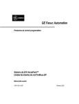
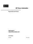
Physical Layout of PBM101/PBM101-12
PROFIBUS DP
OK
PROFIBUS
DP PORT
RUN
RS-232
SERVICE PORT
PWR
PROFIBUS DP
MASTER
Figure 1.1 - Front Cover
Figure 1.2 – Side View
MAN0219-05
15 APR 2003
PAGE 11
CH. 2
CHAPTER 2: INSTALLATION
2.1
PBM101/ PBM101-12 Mounting Requirements
The PBM101/ PBM101-12 Module is designed to plug into any Series 90-30 local slot. The
PBM101/ PBM101-12 requires at least a CPU350 model or higher with Firmware Revision 8. The
PBM101/ PBM101-12 can not operate correctly with a lower version Firmware. Please refer to
the appropriate manufacturer’s installation manual.
2.2
Profibus DP Connector
The 9-pin Profibus DP connector is for physical connection between the slaves and the master.
For further information on the cable and connectors, see Chapter 4 in this manual.
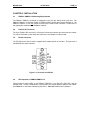
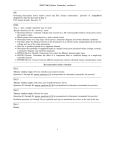
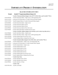
2.3
RS-232 Connector
The RS-232 Service Port is used to upgrade the firmware specific to the slave. This port uses a
standard RS-232 9-pin connector.
5
DTR
RXD
TXD
DCD
4
3
2
1
9
8
7
6
RI
RTS
CTS
DSR
Figure 2.1- Pin-out for the RS-232
2.4
LED Operation of PBM101/PBM101-12
There are three visible LED’s on the PBM101/ PBM101-12, the OK LED, RUN LED, and the
POWER LED. Various combinations of these LED’s will indicate different states of the master.
See Table 2.1 for the states indicated by the LED’s. Table 2.2 indicates fault conditions.
PAGE 12
CH. 2
15 APR 2003
MAN0219-05
Table 2.1 – LED Operation
OK LED
Off
Yellow
RUN LED
Off
Red
POWER LED
Off
Green
Green
Red
Green
Green
Yellow
Green
Green
Green
Green
Red
Blinking
between yellow
and green
Yellow
Meaning
Module not receiving any power.
Module has good power, but has not received valid
configuration from CPU and is not communicating on
the Profibus-DP network.
Module has good power, has received valid
configuration from CPU but is not communicating on
the Profibus-DP network. This may be due to the
CPU being in STOP mode.
Module has good power, has received valid
configuration from CPU and is communicating on the
Profibus-DP network ,but one or more configured
slaves is not responding. Or one or more slave are
flagging that diagnosis needs to be addressed. Or
the network configuration on slave information tab is
not correct.
Module has good power, has received valid
configuration from CPU and is communicating on the
Profibus-DP network. And no slaves have diagnosis
to be addressed.
A fault has occurred.
Refer to the following
description to determine fault.
Table 2.2 – Fault Conditions *
Meaning
An error was encountered receiving configuration from the PLC CPU.
An error was encountered creating the Profibus-DP network
configuration.
4
An internal error was encountered while communicating with the
Profibus hardware
10-23
Internal Error Codes. If witnessed, record value and report to GE
Fanuc.
* The blinking RUN light indicates a fault. To determine the fault, count the number of green
pulses. (The LED pauses for 2 seconds, and pulses green a number of times, and then
repeats the cycle.) Table 1-2 describes the fault as represented by the number of green
pulses.
Pulse Count
2
3
2.5
2.5.1
PBM101/ PBM101-12 Status Error/Diagnosis Reporting
PLC Status Bit Definition
The PBM101/ PBM101-12 has 128 bits of diagnosis and status information reported to the PLC
CPU. 64 bits are assigned as status bits, and 64 are assigned as diagnosis bits. The 64 status
bits are by default assigned to the top of the existing memory map in the Settings tab of the
PBM101/ PBM101-12 parameters screen (see Figure 3.4).
The following explanation describes the Slave Status and indicates the information needed to
setup the Slave Status parameters in the program language being used (such as Ladder Logic or
C-Programming). The Slave Diagnosis inputs contain additional information about the slaves,
which is useful for slave specific issues.
MAN0219-05
15 APR 2003
PAGE 13
CH. 2
This data is contained in 8 bytes with each bit containing the system diagnosis flags for each
slave and is explained later in this chapter. The 64 Diagnosis Flag bits are by default assigned to
the top of the existing memory map in the Settings tab of the PBM101/ PBM101-12 parameters
setup screen (see Figure 3.4).
Status Bits: These 64 bits report the communication status between the master and the slaves
on the bus. Each bit represents the slave area as set up using the Slave Information tab on the
PBM101/ PBM101-12 parameters screen (see Figure 3.5). The following table represents the
area, byte offset, bit offset, and value of each diagnosis bit.
2.5.2
Determining Slave Bus Addresses and Obtaining Slave Status using Status Bits
To obtain a slave status using Status Bits, several pieces of information are needed. The user
must be able to properly “read” various configuration screens in order to obtain the needed
information used to give a slave status. The following example uses configuration screens that
are used in Chapter Three: Configuration in this manual.
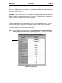
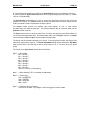
Step 1: Upon selecting the Settings Tab (Figure 3.4), determine which bit has been selected
as the Starting Bit by the VersaPro Programming Software. In Figure 3.4, the Starting
Bit is %I00065, which is the value in the Status Reference Type row.
Figure 3.4 – Settings Tab
PAGE 14
CH. 2
15 APR 2003
MAN0219-05
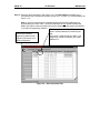
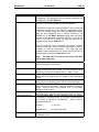
Step 2: Select the Slave Information Tab (Figure 3.5). The Bus Address correlates to the
bus address that is assigned to the slave by the user. In Figure 3.5, the Bus Address for
Slave 1 is “2.”
Note: A common misconception is that Status Bits and Slave Bus Addresses are
represented by the same value. Slave Bus Addresses do not represent Status Bits.
Rather, bits 0-63 are the slave status bits that are assigned by the master configuration
in VersaPro Programming Software.
This column denotes the Bus Addresses of the
slaves. The Bus Address is provided by the
This column is simply the
user.
numbers that VersaPro
This screen is read correctly as “Slave 1 (as
Programming Software has
assigned by VersaPro Software) has a Bus
assigned to the slaves in its
Address of 2.”
master configuration.
Figure 3.5 – Slave InformationTab
MAN0219-05
15 APR 2003
PAGE 15
CH. 2
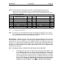
Step 3. Finally, determine the Bit Status of the slave. The Starting Bit value serves as a
reference point for calculating bit offsets. The following worksheet depicts the Bit
Statuses for the example. Refer to Appendix A for a handy work sheet that can be used
for the user’s application.
Example Work Sheet: Determining Slave Bus Addresses
Slave
Area
1
2
3
4
5
6
7
8
2.5.3
Status Reference Type
%I00065
%I00066
%I00067
%I00068
%I00069
%I00070
%I00071
%I00072
(Starting Bit + 0)
(Starting Bit + 1)
(Starting Bit + 2)
(Starting Bit + 3)
(Starting Bit + 4)
(Starting Bit + 5)
(Starting Bit + 6)
(Starting Bit + 7)
Bus
Addr.
2
29
3
N/A
N/A
N/A
N/A
N/A
Slave
Area
34
35
36
37
38
39
40
41
Status Reference Type
%I00098
%I00099
%I00100
%I00101
%I00102
%I00103
%I00104
%I00105
(Starting Bit + 33)
(Starting Bit + 34)
(Starting Bit + 35)
(Starting Bit + 36)
(Starting Bit + 37)
(Starting Bit + 38)
(Starting Bit + 39)
(Starting Bit + 40)
Bus
Addr.
N/A
N/A
N/A
N/A
N/A
N/A
N/A
N/A
PLC Diagnosis Bit Definition
Note: To determine slave bus addresses and obtain slave Diagnostic Flag Bits, refer to Section
2.5.2. Although the procedures in the section cover the use of Status Bits, they are similar
to the procedures that can be used with Diagnostic Flag Bits.
Diagnosis Bits: In addition to 64 status bits, there are 64 diagnosis Flag bits used for monitoring
slave requests to send the diagnosis. These 64 bits are by default assigned to the top of the
existing memory map in the Settings tab of the PBM101/ PBM101-12 configuration screen (see
Figure 3.4). In order to properly configure the master to accommodate the diagnosis data from
the slaves, the Diagnosis Data Slave Address Area, Diagnosis Data Slave Address Length,
Diagnosis Flag Area, Diagnosis Flag Length, Diagnosis Data Area, and the Diagnosis Data
Length must be configured.
Note: The diagnosis bits are ordered in the same manner as the status bits.
a.
Slave diagnosis is not sent to the master without being told to do so where a Flag
is. The Diagnosis Data from the slave is read at the Diagnosis Data Area only
when the bus address is set at the Diagnosis Slave Address Area. This address
must be an %AQ with a length of one word. Diagnosis data from a particular
slave is desired when the slave sets its flag. The address of that slave is entered
into the %AQ selected. The diagnosis data from the slave can be any type of
diagnosis data. Diagnosis data does not necessarily mean that the data
represents a "Fault" condition. It is, however, typically a fault condition.
PAGE 16
CH. 2
15 APR 2003
MAN0219-05
The following are examples of what types of data the slave might send to the
master:
Module Diagnosis:
Corrupted EPROM
Unsupported Feature
Loss of Power
High Alarm
Low Alarm
Over Range
Communications Diagnosis:
Station Not Present
Station Not in Run Mode
Freeze Mode Is Active
Invalid Response
Parameter Fault
b.
The Diagnosis Flag Data is read from the address set as the Diagnosis Flag
Area. The address for this area must be a %I with a length of 64 bits. Each bit
represents a slave number configured on the Slave Information tab of the PBM101/
PBM101-12 setup screen. Diagnostic flag is only valid if the associated status bit is a “1”,
indicating data exchange with this device. The Master will set the diagnosis bit to “1”,
until the slave puts a flag (available diagnostics) on the bus, this allows the Master to set
the diagnosis bit to a “0”. Devices that do not support diagnostics will not allow the
Master to change the diagnosis bits to “0”, unless the Master is not in data exchange
(Status = “0”).
c.
The Diagnosis Data Area is the area in memory set aside for the diagnosis data
coming from the slave. This area must be set as a %AI address and the length will be
dependent on the slave. The length must be set to the largest amount as set by a slave.
For instance; if there are four slaves on the bus and two of them send diagnosis data at a
length of five words and the other two send the data at a length of 12 words, then the
Diagnosis Data Area must be set to 12 words.
It is important to monitor both the status bits and the diagnosis bits both. It is possible to
have diagnosis data without having a problem (fault) on the bus.
For further information on how to setup these areas, see Chapter 3 of this manual.
Note: If both the Status and Diagnosis bits for each slave are AND'ed to together and the result
is a '1,' the Slave is communicating with no faults. If the result is '0,' then test the status
bit.
If the Status bit is zero, the slave is not communicating, and the Diagnosis bit is not
applicable.
If the Status is '1' then the slave is indicating that Diagnosis data is available, and its bus address
needs to be entered to the Diagnosis Slave address area to acknowledge the diagnosis and reset
the Flag.
MAN0219-05
15 APR 2003
PAGE 17
CH. 3
CHAPTER 3: CONFIGURATION
3.1
Configuring the PBM101/ PBM101-12
Chapter Three provides procedures for configuring the PBM101/ PBM101-12 using VersaPro
Programming Software. To install VersaPro, refer to the manufacturer’s software tutorial and
help files included with the software.
Note: The following procedures apply to the PBM101/ PBM101-12. The configuration example
below uses the PBM101.
1. Access the VersaPro Screen using the procedures described in the manufacturer’s software
tutorial (refer to Hardware Configuration).
Note: As part of the manufacturer’s procedures, the user must select Series 90-30 High End
(CPU350 or higher) as the default hardware. A new folder must also be opened. After
these steps are accomplished, a screen similar to Figure 3.1 appears.
Figure 3.1 – VersaPro Screen
2. If the rack type is not correct, place the mouse cursor (arrow) on the rack, press the right
mouse button (right click) and select Change Rack Type.
3. Highlight the slot where the PBM101 is to be placed by left-clicking (or pressing) the
left mouse button on that spot.
PAGE 18
CH. 3
4.
15 APR 2003
MAN0219-05
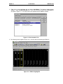
Right click on the highlighted slot and select Add Module. The Module Catalog screen
appears. Select the Bus Controller tab. Then, use the mouse to select the HE693PBM101
as shown in Figure 3.2. The empty slot is now replaced with the PBM101 module.
Figure 3.2 - Bus Controller Tab
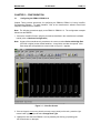
5. The following screen appears (Figure 3.3). Left-click the slot containing the PBM101.
Figure 3.3 – PBM101 Highlighted
MAN0219-05
15 APR 2003
PAGE 19
CH. 3
6. The following screen appears (Figure 3.4).
Figure 3.4 – Settings Tab
7. Select the Settings tab to set parameters for the Master. Alter the parameters using the
information contained in Table 3.1.
a. For additional information covering parameters, refer to Sections 2.5.1 and 2.5.2. Various
parameters involving the slave devices are discussed such as Diagnostic Flag.
PAGE 20
CH. 3
15 APR 2003
MAN0219-05
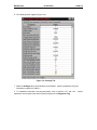
Table 3.1 briefly describes the fields on the Settings Tab, which set parameters for the master.
Table 3.1 – Fields on the Settings Tab
Profibus Station Address 1 - 125
Reference Type for Master Status (Must Be %I).
Represents the location of Status Bits (see Table 1.3 of this
document) in PLC memory. (8 bytes)
Status Length
Number of Status Bits (Fixed at 64)
Baud Rate
Baud Rate of data transmissions on the Profibus network.
(range between 9.6K - 12M)
Min. Slave Interval (.1ms)
Smallest allowed period of time between two successive poll
cycles of a particular slave. It is in .1ms increments and has
a range of 1-65535.
Target Rotation Time (t_bits) Allowable cycle time in which all slaves will be polled by
**
this master. It is in t_bits and has a range of 1-65535.
Bus Address
Status Reference Type
Sync/Freeze Control Area
Sync/Freeze Area Length
Diag. Data Slave Addr. Area
Diag. Data Slave Addr. Area
length.
Reference Area for Sync/Freeze data (Must be a %Q.) For
more information, refer to 3.1, Step 7, item b.
Always 32 Bits.
Reference Area for address of desired Slave with requested
Diagnosis Data. (Must be a %AQ.) See Section 2.5.1 and
2.5.2.
Always one word.
Diagnosis Flag Area
Reference area for Profibus Diagnosis flags. (Must be a
%I.) See Section 2.5.1 and 2.5.2.
Diagnosis Flag Area Length
Always 64 bits.
Module Revision Area
Reference Area for Module Version (Must be %AI).
Module Revision Area Length
Always set to 1.
Diagnosis Data Area
Reference area for address of diagnosis data. (Must be a
%AI.) See Section 2.5.1 and 2.5.2.
Diagnosis Data Area Length
Dependent on slave data. (From 1 to 122)
Slot Time: **
Profibus Slot Time in bit times.
Quiet Time: **
Profibus Quiet time in bit times.
Set Time: **
Profibus Set Time in bit times.
Gap Factor: **
Profibus Gap Factor (1 – 100).
Retry Limit: **
Max Number of message retries.
Min Tsdr: **
Profibus Min Tsdr (station delay time) in bit times.
Max Tsdr: **
Profibus Max Tsdr (station delay time) in bit times.
Resp. Monitoring
Network Response Monitoring Time. Set in 10ms units if
enabled.
(0 to Disable) (10ms units)
** These values will default accordingly for a single Master DP bus at the entered Baud Rate.
A good understanding of the Profibus timed is required if these values are adjusted. Entering
a ‘0’ will also provide default values.
MAN0219-05
15 APR 2003
PAGE 21
CH. 3
b. The following information is provided for the Sync/Freeze function in the Master device and
is used to setup the Sync/Freeze parameters in the program language being used (i.e., Ladder
Logic or C-Programming).
The Sync/Freeze controls allow the Logic to control the data flow to and from the inputs and
outputs of the slaves. The Freeze control can be used to synchronize the slave inputs, and the
SYNC command is used to synchronize the slave outputs.
The Freeze control freezes the physical input data existing on one or more slaves
simultaneously, like taking a snap shot. The selected slave(s) stay in the frozen state until an
Unfreeze control is issued.
The Sync control works in much the same way. It unlocks the physical output data existing on
one or more slaves simultaneously. This data remains static until an Unsync control or new Sync
control is issued. Additional Sync controls update the output data.
The slaves can be selected individually or in groups. To use the group functions, the Slaves must
have been configured for a group. The Slave Information dialog screen contains the Grp Mask
fields for each slave. This field can contain a group number of 0 - 8. The zero group is a global
group.
The format of the Sync/Freeze control data is as follows:
Byte 0 = Group data
Bit 0 = Group 1
Bit 1 = Group 2
Bit 2 = Group 3
Bit 3 = Group 4
Bit 4 = Group 5
Bit 5 = Group 6
Bit 6 = Group 7
Bit 7 = Group 8
data FFH = Group 0, Global group
Byte 1 = Slave Address (7FH = broadcast, all addresses)
Byte 2 = Control type
01H = UNFREEZE
02H = FREEZE
04H = UNSYNC
08H = SYNC
Byte 3 = Transmit Control command
This can be any data - any change in this byte triggers a Control update.
PAGE 22
CH. 3
15 APR 2003
MAN0219-05
8. After the Settings parameters are set, click on the Slave Information tab. The following
screen appears (Figure 3.5).
Figure 3.5 –Slave Information Tab
9. The Slave Information tab is used to define the DP slaves that reside on the Profibus network
and communicate with this Master. Set the parameters using the information contained in
Table 3.2.
MAN0219-05
Slave
GSD File
15 APR 2003
PAGE 23
CH. 3
Table 3.2 – Fields on the “Slave Information” Tab
A number assigned to a slave by the VersaPro Software master
configuration. The assignment is not necessarily identical to the
Bus Address. (See Bus Address.)
The GSD File contains mapping information from the Master to
the Slave. This file is imported from the GSD directory.
The GSD file is required to allow VersaPro to derive operational
parameters for each slave. The GSD file is selected by clicking
in the first available empty box under the GSD File heading.
With the box highlighted, enter a SPACE followed by the
ENTER key. A File Name Selection Dialog starts and allows
the user to find and open the desired GSD file. If the path and
name of the GSD file is known, the path and name can be
entered directly into the GSD File box.
Once the GSD file name is selected and entered, VersaPro
reads the GSD data, and all pertinent parameters is used by
VersaPro to build the configuration. For slaves that have
multiple module configurations, the user is required to enter the
module specific data into the Data Area screen.
Note: The GSD Files are located at the Horner APG Web
site at www.heapg.com.
Bus Address
The Bus Addr field refers to the bus address of the slaves that
are being mapped to this Master.
Sync/Freeze
Non-editable field in slave. Indicates if the module is in the
Freeze Control and/or Sync modes. For more information about
Sync/Freeze Control in the Master, see 3.1, Step 7, item b.
The Ident High field sets the High byte Ident Number of the DPSlave device as assigned by the Profibus Trade Organization
(PTO).
The Ident Low field sets the Low byte Ident number of the DPSlave device as assigned by the Profibus Trade Organization.
The Grp Mask field sets the Bit Mask denoting group control for
Sync and Freeze Functions. Each bit identifies a particular
group. Group Control is only possible if bit 7 in the above
Operating Flags is set to 1.
The Xtra Parm Len indicates the number of bytes entered in the
Parameter Data. Must be in decimal and is limited to 25 bytes.
The Xtra Parm Data provides additional data that pertains
specifically to a particular slave. It is a string of values that can
be entered in decimal or hexadecimal. Values must be
separated as shown:
Ident High
Ident Low
Group Mask
Extra Parameter Length
Extra Parameter Data
Watch Dog
Decimal:
(1,10,0, 32)
Hexadecimal:
(0x1,0xA, 0x0, 0x20)
The WD sets the Watch Dog. The WD is set by the GSD File.
To disable, set to 0.
PAGE 24
CH. 3
15 APR 2003
MAN0219-05
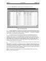
10. Click on the Data Area tab, and the following screen appears (Figure 3.6).
Figure 3.6 – Data Area Tab
a.
This tab completes the configuration for the mapping of the Profibus-DP network data to
the PLC memory locations. The order in which the data is configured must be identical to that of
the DP-Slave and must conform within its GSD file parameters. If configuration mismatches
exist, no data is exchanged with that particular slave.
b.
To configure the slave at bus address 29, start on the next available unused line. (In
Figure 3.6, this is the second line, represented by Area 2) and enter the bus address (for this
example, it is 29). Enter a “1” for the module number. The module type is “I/O,” so left click on
the field with the mouse and select “I/O” from the pull-down menu. The “Length Type” is the data
format (either a byte or a word), and the “Data Length is the number of bytes or words in this
module. The remainder of the lines are used to map the input from the network to the PLC, and
the outputs place updates on to the network.
c.
To configure the input, tab down to the next line (area 2 in Figure 3.6). Enter a “29” for
the
Slave Address. The module a “2”, because the slave is configured for both I/O and inputs. It is
looked at by the master as two modules with the same bus address. Configure the type, length,
and mapping as described by the GSD file. To assist in configuring the slave, the GSD file has
the necessary information needed. If additional assistance is required, please, contact the GE
Fanuc PLC hotline or Horner APG Technical Support.
NOTE: It is important to remember that an input is updated from the network, and an output
places an update on to the network.
MAN0219-05
15 APR 2003
PAGE 25
CH. 3
Table 3.3 – Fields in the “Data Area” Tab
Area
Slave
Address
Module #
Type
Length Type
Data Length
Input Offset
Output Offset
Memory area being defined within the PLC. It is not configurable. The master
currently supports configuring 64 unique areas.
Bus address of the particular slave for which you are adding a data area mapping. It
must be equal to a corresponding value set in the Slave n Settings tab.
Particular module ID which is being configured for the given slave address. The
number of modules used must be identical to the slave configuration for proper data
exchange to occur.
For example, if the slave to which communication is desired is a GE Fanuc Field
Control Profibus BIU which has an input module followed by an output module, the
number of modules would be three. The Module # of the area mapped to the BIU
would be 1; the Module # of the input module would be 2; and the Module # of the
output module would be 3.
Data Type of module being defined. Possible types are: Input, Output, I/O (both input
and output), Special input, Special output, Special I/O, and Empty.
Specifies whether data is of type Byte or Word.
Length of data. This value is expressed in units according to the Length Type field. If
the Type field is set to I/O, this value is both the length of the input and the length of
the output. Range is 0-16. A value of 0 implies that this area is not defined.
Memory location in PLC where input data will be mapped. This field must be set if the
Type value is Input or I/O.
Memory location in PLC where output data will be mapped. This field must be set if
the Type value is Output or I/O.
Special In
Byte
Consistency Option Flag. Possible choices are: “Byte/Word” and “Entire Length”.
(Not used for “Special” Types)
Data Byte used for Types Special Input and Special I/O. This byte (range 0-ff)
represents a special input identifier as defined by a particular slave.
Special Out
Byte
Data Byte used for Types Special Output and Special I/O. This byte (range 0-ff)
represents a special output identifier as defined by a particular slave.
Mfg 1 - 15
Manufacturer Specific Data (1-15) that is sent to a particular slave (up to 15 bytes).
Although the information is usually imported in the GSD file, it is necessary to access if
modifications are required.
Consistency
11. After the Data Area parameters are set, the Power Consumption tab can be selected
to display power consumption characteristics of the module. No fields are editable on this
tab.
12. Save the Configuration.
13. After the configuration is completed, download the configuration to the PLC. Consult the
manufacturer’s manual for details on how to download using VersaPro Programming
Software.
PAGE 26
CH. 3
15 APR 2003
NOTES
MAN0219-05
MAN0219-05
15 APR 2003
PAGE 27
CH. 4
CHAPTER 4: WIRING
4.1
Profibus Wiring
4.1.1
Assembling Cable for Use with DP Port on the PBM101/ PBM101-12 and PBS105.
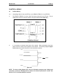
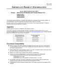
a.
The PBM101/ PBM101-12 uses a 9-pin D-sub plug connector for its DP port. The pin
assignment of the plug connector and the wiring are shown below (Figure 4.1).
Line B
Line A
Figure 4.1
b.
It is necessary to terminate both ends of the network. Both terminations must have
power to them to insure proper operation of the network. The following diagram (Figure
4.2) illustrates the correct connection for the termination resistors.
VP(6)
Line Termination
390 Ohm
B-Line (3)
220 Ohm
Internal
A-Line (8)
390 Ohm
GND(5)
Figure 4.2
NOTE: The above wiring diagram (Fig. 4.2) is for illustrative purposes only. Cabling and
connectors should be PTO-approved to achieve the desired performance results. See
Section 4.1.3 for recommended part numbers.
PAGE 28
CH. 4
15 APR 2003
MAN0219-05
c.
The shield braiding (and if present, the shield foil) must be connected to protective
ground on both sides and must have good conductivity via shield clamps that cover as
large an area as possible. In addition, it is recommended that the data lines be kept
separate from all high-voltage cables.
4.1.2
Other Considerations When Wiring Profibus Network
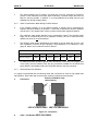
a.
In the Profibus network, up to 32 stations (master or slaves) can be connected per
segment without the addition of repeaters. If more that 32 stations are desired, repeaters
must be used. The repeaters are used to connect individual bus segments together.
b.
The maximum cable length depends on the transmission speed. The specified cable
length can be increased by the use of repeaters. However, the use of more than three
repeaters in series is not recommended.
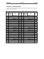
c.
The following cable length specifications are based on type-A cable with a 135 to 165
Ohm impedance; less than 30 pf/m capacity; a loop resistance of 110 Ohms/Km, a wire
gauge of .64mm; and a conductor area of 0.34mm².
Table 4.1 - Baud/Distance Rates
Baud Rate(bit/sec)
9.6K
19.2K
93.75K
187.5K
500K
1.5M
12M
Distance/Segment
1200m
1200m
1200m
600m
200m
200m
100m
d.
For data transmission speeds of greater than 500 kbit/sec., stub lines (free hanging ends
of the cable) must be avoided. There are plug connectors available on the market that
permit data line A and data line B to be connected directly to the plug connector.
4.1.3
Recommended Part Numbers
It is highly recommended that the following cable and connectors be used for high speed data
transmissions. Both cable and connector part numbers are Siemens part numbers.
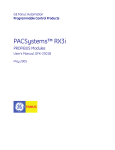
a.
Connectors:
Extra 9-pin DSUB for easy
cable stacking.
6ES7-972-0BB10-0XAO 6ES7-972-0BA10-0XAO
Figure 4.3 - Connectors
b.
Cable: Part Number 6XV1-830-OAH10
MAN0219-05
15 APR 2003
PAGE 29
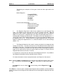
APPENDIX A: USER WORKSHEET
If desired, the following worksheet is available to the user when determining slave bus addresses.
Refer to Sections 2.5.2 and 2.5.3.
User Work Sheet: Determining Slave Bus Addresses
Slave
Area
1
2
3
4
5
6
7
8
9
10
11
12
13
14
15
16
17
18
19
20
21
22
23
24
25
26
27
28
29
30
31
32
33
Status /
Diagnosis
Flag Ref.
Type
Offset
(Starting Bit + 0)
(Starting Bit + 1)
(Starting Bit + 2)
(Starting Bit + 3)
(Starting Bit + 4)
(Starting Bit + 5)
(Starting Bit + 6)
(Starting Bit + 7)
(Starting Bit + 8)
(Starting Bit + 9)
(Starting Bit + 10)
(Starting Bit + 11)
(Starting Bit + 12)
(Starting Bit + 13)
(Starting Bit + 14)
(Starting Bit + 15)
(Starting Bit + 16)
(Starting Bit + 17)
(Starting Bit + 18)
(Starting Bit + 19)
(Starting Bit + 20)
(Starting Bit + 21)
(Starting Bit + 22)
(Starting Bit + 23)
(Starting Bit + 24)
(Starting Bit + 25)
(Starting Bit + 26)
(Starting Bit + 27)
(Starting Bit + 28)
(Starting Bit + 29)
(Starting Bit + 30)
(Starting Bit + 31)
(Starting Bit + 32)
Bus
Addr.
Slave
Area
34
35
36
37
38
39
40
41
42
43
44
45
46
47
48
49
50
51
52
53
54
55
56
57
58
59
60
61
62
63
64
Status /
Diagnosis
Flag Ref.
Type
Offset
(Starting Bit + 33)
(Starting Bit + 34)
(Starting Bit + 35)
(Starting Bit + 36)
(Starting Bit + 37)
(Starting Bit + 38)
(Starting Bit + 39)
(Starting Bit + 40)
(Starting Bit + 41)
(Starting Bit + 42)
(Starting Bit + 43)
(Starting Bit + 44)
(Starting Bit + 45)
(Starting Bit + 46)
(Starting Bit + 47)
(Starting Bit + 48)
(Starting Bit + 49)
(Starting Bit + 50)
(Starting Bit + 51)
(Starting Bit + 52)
(Starting Bit + 53)
(Starting Bit + 54)
(Starting Bit + 55)
(Starting Bit + 56)
(Starting Bit + 57)
(Starting Bit + 58)
(Starting Bit + 59)
(Starting Bit + 60)
(Starting Bit + 61)
(Starting Bit + 62)
(Starting Bit + 63)
Bus
Addr.
PAGE 30
15 APR 2003
MAN0219-05