1
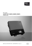
PV Inverter
SUNNY BOY 3000TL / 4000TL / 5000TL
Installation Guide
SB30TL_40TL_50TL-IEN085120 | IME-TB-SBXTL-20 | Version 2.0
EN
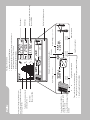
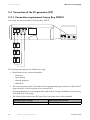
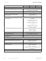
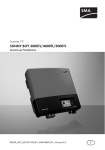
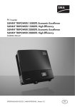
A
B
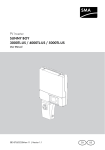
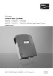
PV generator event number
Input voltage / input current
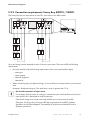
• Sunny Boy might need better ventilation
• Cleaning the fan, if necessary (only for Sunny Boy 4000TL / 5000TL)
Grid event number
Output voltage / output current
Sunny Boy event number
Grid relay
Bluetooth connection to other Sunny Boys
Power reduction due to excessive temperature
Sunny Boy 3000TL: display of both
modules
Sunny Boy 4000TL / 5000TL:
switching between input A and B
every 10 seconds
Please contact SMA.
Device fault
Failure that can be removed on-site
(see chapter 10.2 )
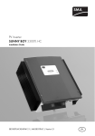
Power curve of the past 16 feed-in hours or
past 16 days (switching the display is done by
knocking on the lid)
• Switching through the line display
• Switching through the energy values of the past 16 feed-in hours to
the daily energy values of the past 16 days
• Activating the background illumination
Knocking on the lower lid:
Text line for displaying an event
Total energy generated since the Sunny
Boy was installed
Daily energy
Current output
SMA Solar Technology AG
Table of Contents
1
1.1
1.2
Notes on this Manual. . . . . . . . . . . . . . . . . . . . . . . . . . . . . . 7
Validity . . . . . . . . . . . . . . . . . . . . . . . . . . . . . . . . . . . . . . . . . . . . 7
Target Group . . . . . . . . . . . . . . . . . . . . . . . . . . . . . . . . . . . . . . . 7
1.3
1.4
1.5
Storage of Manuals . . . . . . . . . . . . . . . . . . . . . . . . . . . . . . . . . . 7
Additional Information . . . . . . . . . . . . . . . . . . . . . . . . . . . . . . . . 7
Symbols Used . . . . . . . . . . . . . . . . . . . . . . . . . . . . . . . . . . . . . . . 8
2
2.1
2.2
Safety . . . . . . . . . . . . . . . . . . . . . . . . . . . . . . . . . . . . . . . . . . 9
Appropriate Usage . . . . . . . . . . . . . . . . . . . . . . . . . . . . . . . . . . . 9
Safety Instructions . . . . . . . . . . . . . . . . . . . . . . . . . . . . . . . . . . . 11
3
3.1
3.2
3.3
Unpacking. . . . . . . . . . . . . . . . . . . . . . . . . . . . . . . . . . . . . . 12
Scope of Delivery . . . . . . . . . . . . . . . . . . . . . . . . . . . . . . . . . . . 12
Check for Transport Damage . . . . . . . . . . . . . . . . . . . . . . . . . . 12
Identification of the Sunny Boy . . . . . . . . . . . . . . . . . . . . . . . . . 12
4
4.1
Mounting the Device . . . . . . . . . . . . . . . . . . . . . . . . . . . . . 13
Selection of the Mounting Location . . . . . . . . . . . . . . . . . . . . . 13
4.1.1
Dimensions and Weight . . . . . . . . . . . . . . . . . . . . . . . . . . . . . . . . . . . . . . . . 13
4.1.2
Ambient Conditions. . . . . . . . . . . . . . . . . . . . . . . . . . . . . . . . . . . . . . . . . . . . 14
4.1.3
Safety clearances . . . . . . . . . . . . . . . . . . . . . . . . . . . . . . . . . . . . . . . . . . . . . 14
4.1.4
Position . . . . . . . . . . . . . . . . . . . . . . . . . . . . . . . . . . . . . . . . . . . . . . . . . . . . . 15
4.2
Mounting Instructions . . . . . . . . . . . . . . . . . . . . . . . . . . . . . . . . 15
4.2.1
Mounting with Wall Bracket . . . . . . . . . . . . . . . . . . . . . . . . . . . . . . . . . . . . . 15
4.2.2
Mounting with Top Hat Rail . . . . . . . . . . . . . . . . . . . . . . . . . . . . . . . . . . . . . 19
5
5.1
5.2
Electrical Connection . . . . . . . . . . . . . . . . . . . . . . . . . . . . . 22
Connection Area Overview . . . . . . . . . . . . . . . . . . . . . . . . . . . 23
Connection to the Public Grid (AC) . . . . . . . . . . . . . . . . . . . . . 24
Installation Guide
SB30TL_40TL_50TL-IEN085120
3
SMA Solar Technology AG
5.3
Connection of the PV generator (DC) . . . . . . . . . . . . . . . . . . . . 30
5.3.1
Connection requirements Sunny Boy 3000TL . . . . . . . . . . . . . . . . . . . . . . . . 30
5.3.2
Connection requirements Sunny Boy 4000TL / 5000TL . . . . . . . . . . . . . . . 31
5.3.3
Connection Procedure. . . . . . . . . . . . . . . . . . . . . . . . . . . . . . . . . . . . . . . . . . 32
5.4
Setting the installation country . . . . . . . . . . . . . . . . . . . . . . . . . 35
5.4.1
Checking the Country Configuration. . . . . . . . . . . . . . . . . . . . . . . . . . . . . . . 36
5.4.2
Configuration with rotary switches . . . . . . . . . . . . . . . . . . . . . . . . . . . . . . . . 38
5.5
Communication. . . . . . . . . . . . . . . . . . . . . . . . . . . . . . . . . . . . . 39
5.5.1
Bluetooth . . . . . . . . . . . . . . . . . . . . . . . . . . . . . . . . . . . . . . . . . . . . . . . . . . . . 39
5.5.2
Fault Signaling Contact . . . . . . . . . . . . . . . . . . . . . . . . . . . . . . . . . . . . . . . . . 40
5.5.3
Installing a Communication Module . . . . . . . . . . . . . . . . . . . . . . . . . . . . . . . 43
6
Commissioning . . . . . . . . . . . . . . . . . . . . . . . . . . . . . . . . . . 45
7
7.1
7.2
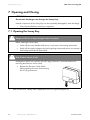
Opening and Closing. . . . . . . . . . . . . . . . . . . . . . . . . . . . . 46
Opening the Sunny Boy . . . . . . . . . . . . . . . . . . . . . . . . . . . . . . 46
Closing the Sunny Boy . . . . . . . . . . . . . . . . . . . . . . . . . . . . . . . 48
8
8.1
Maintenance. . . . . . . . . . . . . . . . . . . . . . . . . . . . . . . . . . . . 50
Checking Heat Dissipation . . . . . . . . . . . . . . . . . . . . . . . . . . . . 50
8.1.1
Cleaning of the fan (only for Sunny Boy 4000TL / 5000TL) . . . . . . . . . . . . 50
8.1.2
Testing the fan (only for Sunny Boy 4000TL / 5000TL) . . . . . . . . . . . . . . . . 51
8.2
Inspection of the Electronic Solar Switch (ESS). . . . . . . . . . . . . 52
9
SD Card Slot . . . . . . . . . . . . . . . . . . . . . . . . . . . . . . . . . . . . 53
10
10.1
10.2
Messages . . . . . . . . . . . . . . . . . . . . . . . . . . . . . . . . . . . . . . 55
Update messages . . . . . . . . . . . . . . . . . . . . . . . . . . . . . . . . . . . 55
Error Messages. . . . . . . . . . . . . . . . . . . . . . . . . . . . . . . . . . . . . 56
11
11.1
11.2
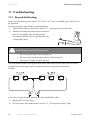
Troubleshooting . . . . . . . . . . . . . . . . . . . . . . . . . . . . . . . . . 62
Ground fault testing . . . . . . . . . . . . . . . . . . . . . . . . . . . . . . . . . 62
Checking the Varistors . . . . . . . . . . . . . . . . . . . . . . . . . . . . . . . 63
4
SB30TL_40TL_50TL-IEN085120
Installation Guide
SMA Solar Technology AG
12
12.1
12.2
12.3
12.4
12.5
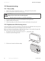
Decommissioning . . . . . . . . . . . . . . . . . . . . . . . . . . . . . . . . 66
Disassembly . . . . . . . . . . . . . . . . . . . . . . . . . . . . . . . . . . . . . . . 66
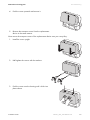
Replacement of the housing covers . . . . . . . . . . . . . . . . . . . . . 66
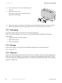
Packaging . . . . . . . . . . . . . . . . . . . . . . . . . . . . . . . . . . . . . . . . . 68
Storage . . . . . . . . . . . . . . . . . . . . . . . . . . . . . . . . . . . . . . . . . . . 68
Disposal . . . . . . . . . . . . . . . . . . . . . . . . . . . . . . . . . . . . . . . . . . 68
13
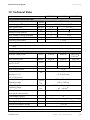
Technical Data . . . . . . . . . . . . . . . . . . . . . . . . . . . . . . . . . . 69
14
Accessories . . . . . . . . . . . . . . . . . . . . . . . . . . . . . . . . . . . . . 72
15
Contact . . . . . . . . . . . . . . . . . . . . . . . . . . . . . . . . . . . . . . . . 73
Installation Guide
SB30TL_40TL_50TL-IEN085120
5
SMA Solar Technology AG
6
SB30TL_40TL_50TL-IEN085120
Installation Guide
SMA Solar Technology AG
Notes on this Manual
1 Notes on this Manual
1.1 Validity
This installation guide describes the installation and commissioning of SMA Solar Technology
inverters of the type Sunny Boy 3000TL (SB 3000TL-20), 4000TL (SB 4000TL-20) and 5000TL
(SB 5000TL-20).
1.2 Target Group
Only qualified electricians may install and commission Sunny Boy units.
1.3 Storage of Manuals
All manuals for the Sunny Boy and the installed components must be stored with the system
documentation and be accessible at all times.
1.4 Additional Information
You can download additional information from the download area at www.SMA.de. Technical
information on the subjects of "laying out of a line circuit breaker" or parameter descriptions for
example is available here.
Installation Guide
SB30TL_40TL_50TL-IEN085120
7
Notes on this Manual
SMA Solar Technology AG
1.5 Symbols Used
The following types of safety instructions and general information appear in this document:
DANGER!
"DANGER" indicates a hazardous situation which, if not avoided, will directly result in
death or serious injury.
WARNING!
"WARNING" indicates a hazardous situation which, if not avoided, could result in death
or serious injury.
CAUTION!
"CAUTION" indicates a hazardous situation which, if not avoided, could result in minor or
moderate injury.
ATTENTION!
"ATTENTION" indicates a situation that can result in property damage if not avoided.
Information
Information provides tips that are valuable for the optimal operation of the product.
8
SB30TL_40TL_50TL-IEN085120
Installation Guide
SMA Solar Technology AG
Safety
2 Safety
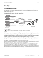
2.1 Appropriate Usage
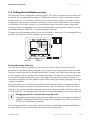
The Sunny Boy is a PV inverter which converts the DC current of a PV generator to AC current and
feeds it into the public grid.
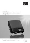
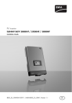
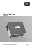
Principle of a PV system with this Sunny Boy
Input A
Distribution
Input B
Sunny Boy
Public grid
PV module
Input B
Input B is only available on the Sunny Boys 4000TL and 5000TL.
The Sunny Boy may only be operated with PV generators (modules and cabling) of protection class
II. Do not connect any sources of energy other than PV modules to the Sunny Boy.
PV modules with large capacities relative to ground, such as thin-film modules with cells on a metallic
substrate, are only to be implemented if their coupling capacity is below 50 nF/kWp.
During grid feeding, a leakage current flows from the cells to ground. The magnitude of this current
depends on the manner in which the modules are installed and, to no small extent, on the weather
(rain, snow). This operational leakage current is not to exceed 50 mA.
When designing the PV system, ensure that the values comply with the permitted operating range of
all components at all times. The free design program "Sunny Design"
(www.SMA.de/en/SunnyDesign) will assist you. The manufacturer of the PV modules must have
approved the modules for use with this Sunny Boy unit. You must also ensure that all measures
recommended by the module manufacturer for long-term maintenance of the module properties are
taken (see also Technical Information "Module Technology", in the download area of www.SMA.de).
Installation Guide
SB30TL_40TL_50TL-IEN085120
9
Safety
SMA Solar Technology AG
Do not use the Sunny Boy for purposes other than those described here. Alternative uses,
modifications to the Sunny Boy or the installation of components not expressly recommended or sold
by SMA Solar Technology invalidates the warranty claims and operation permission.
Authorized Countries
The Sunny Boys 3000TL / 4000TL / 5000TL meet, with the corresponding settings, the requirements
of the following standards and guidelines (as at 12/2008):
• VDE 0126-1-1 (02.2006)
• DK 5940 Ed. 2.2 (02.2006) (Certification of Sunny Boy 3000TL still in process)
• RD 1663/2000 (2000)
• PPC (06.2006)
• AS4777 (2005)
• EN 50438 (12.2007)
Upon request, SMA Solar Technology can set network parameters in-house according to customer
specifications for other countries / installation locations, once these have been tested by SMA Solar
Technology.
You can subsequently make adjustments via changes to the software parameters using relevant
communications products (e.g. Sunny Data Control). For this, however, a personal password is
required, which you can receive from the SMA Serviceline upon request.
10
SB30TL_40TL_50TL-IEN085120
Installation Guide
SMA Solar Technology AG
Safety
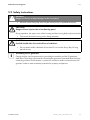
2.2 Safety Instructions
DANGER!
Danger to life due to high voltages in the Sunny Boy!
• All work on the Sunny Boy must only be carried out by a qualified electrician.
CAUTION!
Danger of burn injuries due to hot housing parts!
During operation, the upper cover of the housing and the housing body may become hot.
• Only touch the lower housing cover during operation.
CAUTION!
Possible health risks due to the effects of radiation!
• Do not remain within a distance of less than 20 cm from the Sunny Boy for long
periods of time.
Grounding the PV generator
Comply with the local requirements for grounding the modules and the PV generator.
SMA Solar Technology recommends connecting the generator frame and other electricity
conducting surfaces such that there is continuous conduction and to connect them to the
ground in order to reach maximum protection for property and persons.
Installation Guide
SB30TL_40TL_50TL-IEN085120
11
Unpacking
SMA Solar Technology AG
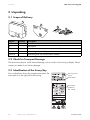
3 Unpacking
3.1 Scope of Delivery
A
B
C
D
Object
A
B
C
D
optional
Quantity
1
1
1
1
1
Description
Sunny Boy
wall bracket
Set of documents with explanations and certificates
Installation guide, including user manual
Installation guide for communication module
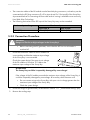
3.2 Check for Transport Damage
Check the Sunny Boy for visible external damage, such as cracks in the housing or display. Please
contact your dealer if you find any damage.
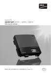
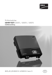
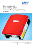
3.3 Identification of the Sunny Boy
You can identify the Sunny Boy using the name plate. The
name plate is on the right side of the housing.
Device type and
version
Serial number:
Grid voltage
(suitable for
220 - 240 V)
12
SB30TL_40TL_50TL-IEN085120
Installation Guide
SMA Solar Technology AG
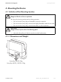
Mounting the Device
4 Mounting the Device
4.1 Selection of the Mounting Location
WARNING!
Danger to life due to fire or explosion!
The Sunny Boy housing can become hot during operation.
• Do not mount the Sunny Boy on flammable construction materials.
• Do not mount the Sunny Boy in areas where highly flammable materials are stored.
• Do not mount the Sunny Boy in areas where there is a risk of explosion.
CAUTION!
Danger of burn injuries due to hot housing parts!
• Mount the Sunny Boy such that it cannot be touched inadvertently.
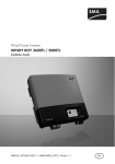
445 mm
4.1.1 Dimensions and Weight
470
mm
m
0m
18
Sunny Boy 3000TL: 22kg
Sunny Boy 4000TL / 5000TL: 25 kg
Installation Guide
SB30TL_40TL_50TL-IEN085120
13
Mounting the Device
SMA Solar Technology AG
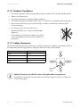
4.1.2 Ambient Conditions
• The mounting location and mounting method must be suitable for the weight and dimensions.
• Mount on a solid surface.
• The mounting location must be accessible at all times.
• The ambient temperature should be below 40 °C at all times to guarantee optimal operation.
• Do not expose the Sunny Boy to direct sunlight, in order to avoid power reduction due to
excessive heating.
• In a living area, do not mount the unit on
plasterboard walls etc. in order to avoid audible
vibrations.
The Sunny Boy can make noises when in use which
can be considered a nuisance when installed in a
living area.
4.1.3 Safety clearances
Observe the following minimum clearances to walls, other devices or objects to guarantee sufficient
heat dissipation and enough space for pulling the Electronic Solar Switch handle.
Direction
sides
above
below
front
Minimum clearance
10 cm
30 cm
50 cm
5 cm
Electronic
Solar
Switch
Multiple Sunny Boys installed in areas with high ambient temperatures
If necessary, increase the clearance and ensure that the supply of cool air is sufficient to
cool the Sunny Boys.
14
SB30TL_40TL_50TL-IEN085120
Installation Guide
SMA Solar Technology AG
Mounting the Device
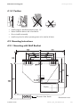
4.1.4 Position
• Install upright or tilted backwards by max. 15°.
• Never install the device with a forward tilt.
• Do not install horizontally.
• Install at eye level to allow operating status to be read at all times.
4.2 Mounting Instructions
4.2.1 Mounting with Wall Bracket
Display
Electronic Solar Switch
Installation Guide
Dimensions in mm
SB30TL_40TL_50TL-IEN085120
15
Mounting the Device
SMA Solar Technology AG
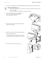
1. Use the wall mounting bracket as a drilling template and mark the positions of the drill holes.
Number of drill holes used
• When wall mounting the unit, use at least two of the horizontal holes and the lowest
hole in the middle.
• Use the two holes in the middle when mounting to a pillar.
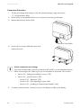
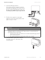
2. Secure the wall bracket using suitable screws
(at least 6 mm in diameter) and washers
(min. outer diameter: 18mm).
3. Transport the Sunny Boy using the handles at the
sides of the Sunny Boy.
4. Attach the Sunny Boy to the wall bracket slightly to
the left of its final position.
The right edge of the rear wall of the Sunny Boy
must be flush with the right edge of the wall bracket.
5. Check both sides for correct positioning.
16
SB30TL_40TL_50TL-IEN085120
Installation Guide
SMA Solar Technology AG
Mounting the Device
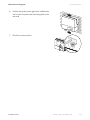
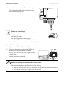
6. Push the Sunny Boy to the right on the wall bracket,
until it locks into place with the locking bolt on the
rear wall.
7. Check for correct position.
Installation Guide
SB30TL_40TL_50TL-IEN085120
17
Mounting the Device
SMA Solar Technology AG
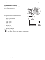
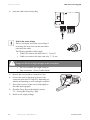
Optional anti-theft protection
The Sunny Boy can be secured to the wall bracket with a
lock to protect it against theft.
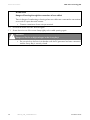
The lock must meet the following requirements:
• Size:
A: 6 - 10 mm in diameter
B: 21 - 35 mm
C: 20 - 33 mm
D: 40 - 60 mm
E: 13 - 21 mm
• Stainless steel
• hardened shackle
• secured cylinder lock
Storing the key
Store the key carefully in case the device needs servicing.
18
SB30TL_40TL_50TL-IEN085120
Installation Guide
SMA Solar Technology AG
Mounting the Device
4.2.2 Mounting with Top Hat Rail
Requirements for mounting of the top hat rail
• Use a TH-35-7.5 mounting rail compliant with DIN EN 60715.
• Use stainless steel top hat rails and screws to prevent contact corrosion.
• Mount on level surfaces only.
• Use fastening material suitable for the surface.
Take into account the weight of the Sunny Boy when selecting fastening materials.
Mounting Procedure
1. Use the top hat rail as a drilling template and mark the positions of the drill holes.
2. Secure the top hat rail using suitable screws
(at least 6 mm in diameter) and washers
(min. outer diameter: 18mm).
Secure one screw at least every 300 mm.
3. Transport the Sunny Boy using the handles at the
sides of the Sunny Boy.
4. Attach the Sunny Boy to the top hat rail using the
mounting opening in the rear wall.
Installation Guide
SB30TL_40TL_50TL-IEN085120
19
Mounting the Device
SMA Solar Technology AG
5. Check both sides for correct positioning.
In order to prevent the Sunny Boy being pulled off, you must also screw it to the wall. To do so,
proceed as follows:
1. Remove the Electronic Solar Switch by pulling it
downwards.
2. Loosen all six non-removable lid screws and
remove the cover.
3. Drill through hole in the rear wall of the housing.
4. Use a suitable drill bit at least 120 mm in length.
5. Insert a wall anchor of the correct size.
20
SB30TL_40TL_50TL-IEN085120
Installation Guide
SMA Solar Technology AG
Mounting the Device
6. Secure the Sunny Boy with a screw.
The screw must meet the following requirements:
Length:
Diameter:
Screw head:
min. 100 mm
>8 mm
not hexagon head,
not countersunk
7. Check that the unit is secure.
Installation Guide
SB30TL_40TL_50TL-IEN085120
21
Electrical Connection
SMA Solar Technology AG
5 Electrical Connection
WARNING!
Electric shock due to short circuit!
If cables with different voltages are laid parallel to one another, short circuits can result if
the cable insulation becomes damaged.
• Lay all cables separately.
ATTENTION!
Electrostatic discharges can damage the Sunny Boy!
Internal components of the Sunny Boy can be irreparably damaged by static discharge.
• Ground yourself before touching a component.
22
SB30TL_40TL_50TL-IEN085120
Installation Guide
SMA Solar Technology AG
Electrical Connection
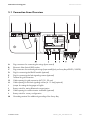
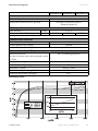
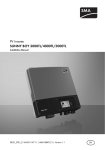
5.1 Connection Area Overview
A
B
C
D
E
F
G
H
I
J
K
L
M
Plug connectors for connecting the strings (input area A)
Electronic Solar Switch (ESS) socket
Plug connectors for connecting the strings (input area B)(only on Sunny Boy 4000TL / 5000TL)
Plug for connecting the RS485 module (optional)
Plug for connecting the fault signaling contact (optional)
Terminal for grid connection
Cable opening for grid connection (AC) (12 - 25 mm)
Cable opening for the fault signaling contact (6 - 12 mm) (optional)
Jumper for setting the language to English
Rotary switch for setting Bluetooth communication
Cable opening for communication via RS485 (optional)
Rotary switch for country configuration
Grounding terminal for additional grounding of the Sunny Boy
Installation Guide
SB30TL_40TL_50TL-IEN085120
23
Electrical Connection
SMA Solar Technology AG
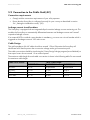
5.2 Connection to the Public Grid (AC)
Connection requirements
• Comply with the connection requirements of your utility operator.
• Ensure that the Sunny Boy is configured correctly for your country as described in section
5.4 „Setting the installation country“ (35).
Leakage current circuit breakers
The Sunny Boy is equipped with an integrated all-pole sensitive leakage current monitoring unit. This
enables the Sunny Boy to automatically differentiate between real leakage currents and "normal"
capacitive leakage currents.
If an external RCD or residual current breaker is mandatory, you must use a circuit breaker which is
triggered at a leakage current of 100 mA or more.
Cable Design
The grid impedance of th AC cable should not exceed 1 Ohm. Otherwise the Sunny Boy will
deactivate at full feed-in power due to excessive voltage at the grid connection point.
The cable cross-section should be sized using the "Sunny Design" design program (www.SMA.de) so
that output losses do not exceed 1 % at nominal power.
The maximum cable length for each cable cross section is shown in the following table. Do not exceed
the maximum cable length.
Cable cross section
4.0 mm²
6.0 mm²
8.0 mm²
10.0 mm²
24
SB 3000TL-20
23.5 m
35.2 m
47 m
58.7 m
SB30TL_40TL_50TL-IEN085120
Max. cable length
SB 4000TL-20
not permitted
23.3 m
31.1 m
38.8 m
SB 5000TL-20
not permitted
18.6 m
24.8 m
31.1 m
Installation Guide
SMA Solar Technology AG
Electrical Connection
Load Disconnection Unit
You must safeguard each inverter with an individual circuit breaker in order that the inverter can be
safely disconnected under load. The maximum permissible fuse protection is located in the technical
data.
WARNING!
Danger to life due to fire!
If more than one inverter is connected in parallel to the same circuit breaker, the protective
function of the circuit breaker is no longer guaranteed. This can lead to cable fire or the
destruction of the inverter.
• never connect more than one inverter to one circuit breaker.
• Comply with the maximum permissible fuse protection when selecting the circuit
breaker.
WARNING!
Danger to life due to fire!
When a generator (Sunny Boy) and a consumer are connected to the same line circuit
breaker, the protective function of the line circuit breaker is no longer guaranteed. The
current from the Sunny Boy and the grid can add up to overcurrent which is not detected
by the line circuit breaker.
• Never connect consumers between the Sunny Boy and the circuit breaker without
protection.
• Always install separate fuses for consumers.
Permissible Load Disconnection Unit
Use only circuit breakers as load disconnection units!
A screw type fuse element, e.g. D system (Diazed) or D0 system (Neozed) is not a load
disconnection device, and thus may not be used as a load disconnection unit. Upon
disconnection under load, the screw type fuse element may be destroyed, or its
functionality may be inhibited by contact burning. It only acts as cable protection.
Cable Requirements
External
diameter
Wire cross section
PE
L
N
The PE wire must be 5 mm longer than the L and N wires.
Installation Guide
SB30TL_40TL_50TL-IEN085120
25
Electrical Connection
SMA Solar Technology AG
Connection Procedure
1. Test the grid voltage and compare it with the permitted voltage range (see section
13 „Technical Data“ (69)).
2. Switch off the circuit breaker and secure it to prevent it from being reactivated.
3. Remove the Electronic Solar Switch.
Electronic Solar Switch
4. Loosen all six non-removable lid screws and
remove the cover.
Further connections and settings
If you want to make further connections other than AC and DC, you should make them now
before connecting the AC cable to give you more freedom of movement. This includes:
• Section 5.4 „Setting the installation country“ (35)
• Section 5.5 „Communication“ (39)
– Section 5.5.1 „Bluetooth“ (39)
– Section 5.5.2 „Fault Signaling Contact“ (40)
– Section 5.5.3 „Installing a Communication Module“ (43)
5. To make connection easier, loosen the screw on the display and flip up the display.
26
SB30TL_40TL_50TL-IEN085120
Installation Guide
SMA Solar Technology AG
Electrical Connection
6. Loosen the union nut of the AC screw clamp (see
"G" on Page 23) slightly and remove the dummy
plug from the cable opening.
Seal in the screw clamp
There is a two-part seal in the screw clamp. If
necessary, the inner insert can be removed to
insert a thicker cable.
The following guideline values apply:
• Cable cross section with both seals: 12 - 16 mm
• Cable cross section with outer seal only: 15 - 21 mm
7. Pull cable through.
8. Flip up terminals of the AC terminal fully.
9. Connect L, N and the protective earth (PE) to the
AC terminal in accordance with the labels.
For this, the PE wire must be 5 mm longer than the
L and N wires!
L and N may not be swapped!
CAUTION!
Danger of crushing when the terminals snap closed!
The terminals snap down rapidly and hard when closing.
• Press the terminals down with your thumb, do not grip the entire terminal on all sides.
• You should not hold your fingers under the terminal.
Installation Guide
SB30TL_40TL_50TL-IEN085120
27
Electrical Connection
SMA Solar Technology AG
ATTENTION!
Danger of burning through the connection of two cables!
There is danger of overheating or burning when two cables are connected to one terminal
as a result of a poor electrical contact.
• Connect a maximum of one wire per terminal.
10. Close all terminals of the AC terminal again.
11. Screw the union nut of the screw clamp tightly to the cable opening again.
DANGER!
Danger to life due to high voltages in the Sunny Boy!
• Do not switch on the line circuit breaker until the PV generator has been connected
and the Sunny Boy is securely closed.
28
SB30TL_40TL_50TL-IEN085120
Installation Guide
SMA Solar Technology AG
Electrical Connection
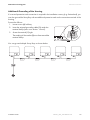
Additional Grounding of the Housing
If a second protective earth connection is required in the installation country (e.g. Switzerland), you
can also ground the Sunny Boy with an additional protective earth on the connection terminal of the
housing.
Proceed as follows:
1. Loosen screw (A) halfway.
A
B
C
2. Insert the stripped grounding cable (D) under the
terminal clamp (max. cross section: 16 mm²).
3. Screw the terminal (C) tight.
The toothing of the washer (B) must face toward the
terminal clamp.
D
You can ground multiple Sunny Boys as shown below:
Installation Guide
SB30TL_40TL_50TL-IEN085120
29
Electrical Connection
SMA Solar Technology AG
5.3 Connection of the PV generator (DC)
5.3.1 Connection requirements Sunny Boy 3000TL
Two strings can be connected to the Sunny Boy 3000TL
The following requirements are valid for the strings:
• Requirements for the connected modules:
– same type
– same quantity
– identical alignment
– identical tilt
• The connecting wires of the PV module must be equipped with plug connectors to allow the DC
plug connectors of the Sunny Boy to be connected to it.
A pre-assembled set for connecting the free cable ends of a string is available as an accessory
from SMA Solar Technology:
• The following limit values at the DC input of the Sunny Boy may not be exceeded:
Maximum input voltage
550 V (DC)
30
SB30TL_40TL_50TL-IEN085120
Maximum input current
17.0 A (DC)
Installation Guide
SMA Solar Technology AG
Electrical Connection
5.3.2 Connection requirements Sunny Boy 4000TL / 5000TL
The Sunny Boy has two input areas "A" and "B", each with its own MPP tracker.
Up to two strings can be attached to each of the two input areas. These must fulfill the following
requirements:
• Per input area (A or B) the following requirements of the connected modules apply:
– same type
– same quantity
– identical alignment
– identical tilt
• When connecting only two identical strings, it is more efficient to connect them to just one input
area.
Exception: shadowed strings or if the total input current is greater than 15 A.
No mixed connection of input areas
,
For example, if the plus pole of a string is connected to input area A and the minus pole to
input area B, this is described as mixed connection.
Connect the strings to one input area only and do not mix input areas A and B!
Otherwise, the Sunny Boy no longer fulfills the requirements of the EMC guideline
(guideline on the ElectroMagnetic Compatibility of a device) and therefore loses its
operation permission.
Installation Guide
SB30TL_40TL_50TL-IEN085120
31
Electrical Connection
SMA Solar Technology AG
• The connection cables of the PV module must be fitted with plug connectors, so that they can be
connected to the DC plug connectors (2 x 2 for input A and 2 x 2 for input B) of the Sunny Boy.
A pre-assembled set for connecting the free cable ends of a string is available as an accessory
from SMA Solar Technology:
• The following limit values at the DC input of the Sunny Boy may not be exceeded:
Maximum input voltage
550 V (DC)
Maximum input current
Input area A
Input area B
15.0 A (DC)
15.0 A (DC)
5.3.3 Connection Procedure
DANGER!
Danger to life due to high voltages in the Sunny Boy!
• Before connecting the PV generator, ensure that the AC line circuit breaker is
switched off.
1. Check the connection cables of the PV modules for
correct polarity and that the maximum input voltage
of the Sunny Boy is not exceeded.
Check the system design if the open circuit voltage
of the PV modules is less than 10 % below the
maximum input voltage of the Sunny Boy.
ATTENTION!
The Sunny Boy could be irreparably damaged by overvoltage!
If the voltage of the PV modules exceeds the maximum input voltage of the Sunny Boy, it
could be irreparably damaged by overvoltage. All warranty claims become void.
• Do not connect strings to the Sunny Boy with open circuit voltage greater than the
maximum input voltage of the Sunny Boy.
• Check the system design.
2. Check the strings for ground faults, as described in section 11.1 „Ground fault testing“ (62).
3. Remove the sealing caps.
32
SB30TL_40TL_50TL-IEN085120
Installation Guide
SMA Solar Technology AG
Electrical Connection
4. Connect the DC plug connectors.
Ensure that the strings are assigned correctly (as
described at the beginning of the section). Unused
DC input sockets must be sealed with sealing caps.
The Sunny Boy 3000TL only has input area A!
5. Close the cover using the six screws again.
Tighten the screws in the sequence shown on the
right to a torque of 1.4 Nm.
DANGER!
Risk of lethal electric shock!
A dangerous electric arc can form if the DC plug connector is removed without first
removing the Electronic Solar Switch.
• Operate the Sunny Boy only when the cover is closed so that the DC plug connectors
cannot simply be removed.
• Do not plug in the Electronic Solar Switch until the cover is closed.
6. Check the Electronic Solar Switch for wear as
described in section 8.2 and connect it after
successful testing.
Installation Guide
SB30TL_40TL_50TL-IEN085120
33
Electrical Connection
SMA Solar Technology AG
ATTENTION!
Damage to the Electronic Solar Switch!
If inserted incorrectly the Electronic Solar Switch can become damaged.
• Press the handle firmly into place on the socket of the Electronic Solar Switch! The
handle must be flush with the housing.
• Check that the unit is secure.Check that the unit is secure.
You can now commission the Sunny Boy as described in section 6 „Commissioning“ (45). The
following connections and settings are optional.
34
SB30TL_40TL_50TL-IEN085120
Installation Guide
SMA Solar Technology AG
Electrical Connection
5.4 Setting the installation country
The Sunny Boy can be configured for several countries. This is done using two rotary switches in the
Sunny Boy or by configuring the parameters "GridGuard.CntrySet" using a communication device.
Switch position 0 / 0 is the setting on delivery. If you ordered the Sunny Boy with specific country
configurations, the settings were made in the factory using a communication device. These settings
are overwritten if the rotary switches or a communication device are used to make changes and
cannot be restored automatically. If the unit was ordered without specifying the installation country,
the standard setting is VDE0126-1-1 and the language is German.
Changes are saved immediately after the line circuit breaker is switched on. If an unassigned switch
position is selected, the Sunny Boy displays an error message.
Switch A
Switch B
Protected country data sets
The local grid connection regulations in some countries require a device which prevents the
parameters for grid feeding being changed. For this reason, some country data sets are protected.
Protected country data sets are automatically blocked 10 feed-in hours after commissioning or after
the last change. If the country data set is changed after these 10 feed-in hours, the Sunny Boy does
not accept the changes and displays the error message "Grid parameters locked". However, if a
retrospective change to the country data set only involves changing the display language, the change
is saved immediately.
The country data sets can also be set, manually locked or unlocked using a communication device
("GridGuard.CntrySet" parameter). The parameter "Inst.-Code" must be set to "54321" to lock the
data set. It can only be unlocked by entering a personal unlocking code and is valid for a maximum
of 10 feed-in hours. The language can be set without a password regardless of the country data set.
Changing parameters in protected country data sets
If parameters are changed in protected country data sets, they are no longer protected and
"adjusted" is displayed instead of the standard. The parameter "Inst.-Code" must be set to
"54321" to lock the data set manually.
The last change (switch or communication device) is always checked and accepted if applicable. I.e.
the switch position may not always show the actual country configuration.
Installation Guide
SB30TL_40TL_50TL-IEN085120
35
Electrical Connection
SMA Solar Technology AG
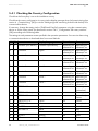
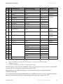
5.4.1 Checking the Country Configuration
Check that the Sunny Boy is set to the installation country.
Check that the country configuration is correct via the display message when (re-)commissioning (see
section 6 „Commissioning“ (45)) or via the "SMA grid guard" measuring channel with the help of a
communication device.
If necessary, change the setting via the "GridGuard.CntrySet" parameter using the communication
device or via the rotary switch (as described in section 5.4.2 „Configuration with rotary switches“
(38)) according to the following table.
The settings in each parameter set are specified in the operation parameters. You can view these using
a communication device or download them from www.SMA.de.
(A) (B) Parameter set
Display language
0 0 Condition upon delivery Condition upon delivery
0
1
is retained
English
0
2
is retained
German
0
3
is retained
French
0
4
is retained
Spanish
0
5
is retained
Italian
0
6
is retained
Greek**
0
7
is retained
Czech**
1
0
VDE0126-1-1
German
Protection
depending on
parameter set
depending on
parameter set
depending on
parameter set
depending on
parameter set
depending on
parameter set
depending on
parameter set
depending on
parameter set
depending on
parameter set
yes
1
1
1
8
VDE0126-1-1 A a)
VDE0126-1-1
German
French
yes
yes
1
2
2
3
3
4
4
9
0
8
0
8
0
8
VDE0126-1-1 Bb)
VDE0126-1-1
AS4777
DK5940E2.2
French
Italian
English
Italian
German
Spanish
Greek**
yes
yes
no
no
no
yes
no
36
RD1663
PPC
SB30TL_40TL_50TL-IEN085120
Country
depending on
parameter set
depending on
parameter set
depending on
parameter set
depending on
parameter set
depending on
parameter set
depending on
parameter set
depending on
parameter set
depending on
parameter set
Germany,
Switzerland,
Germany
Switzerland,
France
France
Switzerland
Australia
Italy
Italy
Spain
Greece
Installation Guide
SMA Solar Technology AG
Electrical Connection
(A)
4
5
5
6
6
6
6
6
6
6
7
(B)
9
0
8
0
1
2
3
4
5
6
0
Parameter set
PPC*
Kepco-guide
G 83/1
EN 50438
EN 50438
EN 50438
EN 50438
EN 50438
EN 50438
EN 50438
EN50438-CZ
Display language
English
English
English
German
English
French
Italian
Spanish
Greek**
Czech**
Czech**
Protection
no
no
no
yes
yes
yes
yes
yes
yes
yes
yes
7
1
EN50438-CZ
English
yes
7
2
EN50438-CZ
German
yes
7
7
7
E
E
E
E
E
E
E
F
8
9
A
0
1
2
3
4
5
6
0
C10/11*
C10/11*
C10/11*
Off-Grid
French
English
German
English
German
French
Spanish
Italian
Greek**
Czech**
SD card
yes
yes
yes
no
no
no
no
no
no
no
no
SD card
a)
Special setting: parameter "GridGuard.VolCtl.Rpro" = 244 V instead of 253 V
b)
Special setting: Bluetooth transmission power reduced (in accordance with French requirements)
*)
Availability on request
**)
Currently not available. The previously set display language remains.
Country
Greece
South Korea
England
various EU
countries
Czech
Republic
Czech
Republic
Czech
Republic
Belgium
Belgium
Belgium
Flexible
Flexible
If the Sunny Boy is not set for the installation country, set it using the two rotary switches as described
in section 5.4.2 „Configuration with rotary switches“ (38).
Alternatively you can make the settings via a communication device using the parameter
"GridGuard.CntrySet".
If you require parameter settings adjusted for your installation location, you can change them with the
help of a communication device or copy settings to the Sunny Boy using an SD card.
Installation Guide
SB30TL_40TL_50TL-IEN085120
37
Electrical Connection
SMA Solar Technology AG
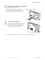
5.4.2 Configuration with rotary switches
Proceed as follows for the configuration:
1. Open the Sunny Boy as described in section 7.1 „Opening the Sunny Boy“ (46).
2. Set the arrows on the rotary switches to the
required position using a screwdriver (2.5 mm).
Jumper for English language
You can also set the language to English using
a jumper (e.g. for service purposes in other
countries). To do so, plug the jumper onto the
upper two pins as shown on the right.
3. Close the Sunny Boy as described in section 7.2 „Closing the Sunny Boy“ (48).
38
SB30TL_40TL_50TL-IEN085120
Installation Guide
SMA Solar Technology AG
Electrical Connection
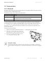
5.5 Communication
5.5.1 Bluetooth
Bluetooth communication with a communication device is activated by default. Bluetooth networking
with other inverters is deactivated ex works.
The following settings can be made via the rotary switch:
Switch position (NetID) Setting
0
Off
1
Bluetooth communication with communication device possible, no
networking with other inverters (factory setting).
2 ... F
Networking with other inverters
In order to distinguish the inverters of your system from those of adjacent systems for Bluetooth
communication, you can assign an individual NetID for the inverters in your system (switch setting
2 ... F). However, this is only necessary if the adjacent system is within 500 m of your system.
All inverters in your system must have the same NetID to ensure that they are registered by your
communication device.
To this end, proceed as follows:
1. Open the Sunny Boy as described in section 7.1 „Opening the Sunny Boy“ (46).
2. Set the arrow on the right rotary switch to the
required position using a screwdriver (2.5 mm).
3. Close the Sunny Boy as described in section
7.2 „Closing the Sunny Boy“ (48).
Saving the settings
The Bluetooth settings do not become active until the line circuit breaker is switched on
again and after the PV generator is connected and the Electronic Solar Switch is plugged
in.
Installation Guide
SB30TL_40TL_50TL-IEN085120
39
Electrical Connection
SMA Solar Technology AG
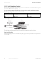
5.5.2 Fault Signaling Contact
The Sunny Boy is fitted with a fault signaling contact as standard. It is connected simultaneously with
the red error LED beside the display.
You can connect a separate consumer both in the event of errors and for trouble-free operation.
The following voltages and currents can be connected:
Voltage
Max. 240 V
max. 30 V
AC
DC
Current
max. 1.0 A
max. 1.0 A
Cable Requirements
External
diameter
Wire
cross-section
Double insulated
The cable type and laying method must be suitable for the application and use location.
Line circuit breaker
If the fault signaling contact is connected to the public grid, it must be protected with a separate line
circuit breaker.
40
SB30TL_40TL_50TL-IEN085120
Installation Guide
SMA Solar Technology AG
Electrical Connection
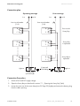
Connection plan
Operating message
L or
Error message
L or
or N
Line circuit breaker
Line circuit breaker
(1 A)
(1 A)
B
B
F
F
B
B
F
F
B
B
F
F
or N
Error on the
Sunny Boy
Sunny Boy
in operation
Sunny Boy in
operation
if required.
Grounding
Light on
Trouble-free
operation (B)
Light on
Error (F)
Connection Procedure
1. Switch off AC and DC supply voltage.
2. Open the Sunny Boy as described in section 7.1 „Opening the Sunny Boy“ (46).
3. Loosen the union nut of the screw clamp (see "H" Page 23) slightly and remove the dummy plug
from the cable opening.
Installation Guide
SB30TL_40TL_50TL-IEN085120
41
Electrical Connection
SMA Solar Technology AG
4. Insert the cable into the Sunny Boy.
Seal in the screw clamp
There is a two-part seal in the screw clamp. If
necessary, the inner insert can be removed to
insert a thicker cable.
The following guideline values apply:
• Cable cross section with both seals: 5 - 7 mm 65
• Cable cross section with outer seal only: 7 - 13 mm
DANGER!
Danger to life due to high voltages in the Sunny Boy!
• Do not use cables with single insulation.
• Strip a maximum 15 mm of cable sheath.
5. Remove the wire insulation a maximum 8 mm.
6. Connect the wires to the plug as shown in the
connection plan (see "E" Page 23), depending on
whether an operating or error message is required.
7. Secure the union nut of the screw clamp tightly to
the cable opening again.
8. Close the Sunny Boy as described in section
7.2 „Closing the Sunny Boy“ (48).
9. Switch on the supply voltage.
42
SB30TL_40TL_50TL-IEN085120
Installation Guide
SMA Solar Technology AG
Electrical Connection
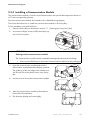
5.5.3 Installing a Communication Module
The communication module is used for wired communication with special data acquisition devices or
a PC with corresponding software.
See the communication module documentation for a detailed wiring diagram.
This section describes how to install the communication module in the Sunny Boy.
For the installation, proceed as follows:
1. Open the Sunny Boy as described in section 7.1 „Opening the Sunny Boy“ (46).
2. Unscrew the display screw and flip the display up
until it locks into place.
ATTENTION!
Damage to the communication module!
The communication module can be irreparably damaged by electrostatic discharge.
• Ground yourself before you remove the communication module from the packaging.
3. Insert the communication module and push the
ribbon cable, situated behind the display, upwards.
The guide lug of the rear edge of the module must
slot into the hole in the plastic mount in the Sunny
Boy.
4. Use the screw to secure the communication module.
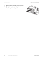
5. Wire the communication module as described in
the module documentation.
6. Flip down the display and screw tightly.
Installation Guide
SB30TL_40TL_50TL-IEN085120
43
Electrical Connection
SMA Solar Technology AG
7. Attach the ribbon cable to the multipoint connector.
8. Close the Sunny Boy as described in section
7.2 „Closing the Sunny Boy“ (48).
44
SB30TL_40TL_50TL-IEN085120
Installation Guide
SMA Solar Technology AG
Commissioning
6 Commissioning
Check the following requirements before commissioning:
• Secure fit on wall bracket / top hat rail
• Correct country configuration (see section 5.4.2 )
• correct connection of the AC (grid) cable
• Full connection of the DC cables (PV strings)
• Unrequired DC plug connectors in the DC connection area are sealed with sealing caps
• All housing openings are sealed
• the housing cover is securely screwed in place
• The Electronic Solar Switch is securely plugged in
• The AC distribution is installed correctly
Commissioning Procedure
1. Switch on the line circuit breaker.
2. If the radiation is sufficient, an illuminated green
LED indicates undisturbed feeding-in. If this is the
case, commissioning has been completed
successfully.
If the green LED flashes for an extended period, this
may be due to the fact that the DC radiation is not
sufficient.
Measurements can only be made if the DC radiation is sufficient.
3. The meaning of the illuminated red LED and the meaning of the event numbers on the display
are described in section10.2 „Error Messages“ (56).
Display on initialization
1. First, the text line shows the firmware version of the
internal processors.
2. After 5 seconds or after you knock on the cover, the
series number or the identifier of the inverter are
displayed. This identifier can be changed using a
communication device.
3. After a further 5 seconds or when you knock again,
the configured standard is displayed.
4. After a further 5 seconds or when you knock again,
the configured language is displayed.
5. During normal operation, the scrolling text line of
the display is subsequently empty. See section 10 „Messages“ (55) for the possible event
messages and their meaning which can be displayed in the scrolling text line.
Installation Guide
SB30TL_40TL_50TL-IEN085120
45
Opening and Closing
SMA Solar Technology AG
7 Opening and Closing
ATTENTION!
Electrostatic discharges can damage the Sunny Boy!
Internal components of the Sunny Boy can be irreparably damaged by static discharge.
• Ground yourself before touching a component.
7.1 Opening the Sunny Boy
DANGER!
Danger to life due to high voltages in the Sunny Boy!
Before opening the Sunny Boy:
• Switch off the circuit breaker and secure it to prevent it from being reactivated.
• Switch off the supply voltage to the fault signaling contact and secure it to prevent it
from being reactivated (if applicable).
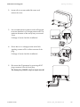
DANGER!
Risk of lethal electric shock!
A dangerous electric arc can form if the DC plug connector is removed without first
removing the Electronic Solar Switch.
• Remove the Electronic Solar Switch
before opening the cover and removing
the DC plug connectors.
1. Wait until the LEDs, display and, if applicable, the error signal have gone out.
46
SB30TL_40TL_50TL-IEN085120
Installation Guide
SMA Solar Technology AG
Opening and Closing
2. Loosen all six non-removable lid screws and
remove the cover.
3. Use a suitable measuring device on the AC terminal
to ensure that there is no voltage present at PE. The
maximum diameter of the test tip may not exceed
2 mm.
If voltage is found, check the installation!
4. Ensure there is no voltage present at the fault
signaling contact to PE on all test contacts of the
plug.
If voltage is found, check the installation!
5. Disconnect the PV generator by removing all DC
plug connectors from the Sunny Boy.
The Sunny Boy 3000TL only has input area A!
Installation Guide
SB30TL_40TL_50TL-IEN085120
47
Opening and Closing
SMA Solar Technology AG
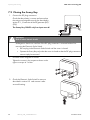
7.2 Closing the Sunny Boy
1. Connect the DC plug connectors.
Check that the polarity is correct and ensure that
the strings are assigned correctly (as described in
section 5.3 „Connection of the PV generator (DC)“
(30)).
The Sunny Boy 3000TL only has input area A!
DANGER!
Risk of lethal electric shock!
A dangerous electric arc can form if the DC plug connector is removed without first
removing the Electronic Solar Switch.
• Do not plug in the Electronic Solar Switch until the cover is closed.
• Operate the Sunny Boy only when the cover is closed so that the DC plug connectors
cannot simply be removed.
1. Close the cover using the six screws.
Tighten the screws in the sequence shown on the
right to a torque of 1.4 Nm.
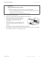
2. Check the Electronic Solar Switch for wear as
described in section 8.2 and connect it after
successful testing.
48
SB30TL_40TL_50TL-IEN085120
Installation Guide
SMA Solar Technology AG
Opening and Closing
ATTENTION!
Damage to the Electronic Solar Switch!
If inserted incorrectly the Electronic Solar Switch can become damaged.
• Press the handle firmly into place on the socket of the Electronic Solar Switch! The
handle must be flush with the housing.
• Check that the unit is secure.Check that the unit is secure.
3. Switch on the line circuit breaker.
4. Switch on the supply voltage of the fault signaling contact (if present).
5. If the radiation is sufficient, an illuminated green
LED indicates undisturbed feeding-in. If this is the
case, commissioning has been completed
successfully.
If the green LED flashes for an extended period, this
may be due to the fact that the DC radiation is not
sufficient.
Measurements can only be made if the DC radiation is sufficient.
6. The meaning of the illuminated red LED and the meaning of the event numbers on the display
are described in section10.2 „Error Messages“ (56).
Installation Guide
SB30TL_40TL_50TL-IEN085120
49
Maintenance
SMA Solar Technology AG
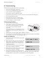
8 Maintenance
8.1 Checking Heat Dissipation
If the Sunny Boy often loses power due to overheating (temperature symbol on the display lights up),
this can be for the following reasons:
• The cooling fins on the rear of the housing are covered in dirt.
• The ventilation channels on the top are covered in dirt.
• The fan is clogged (only Sunny Boy 4000TL / 5000TL).
Clean the cooling fins and ventilation channels with a soft brush if necessary. Clean the fan as
described below.
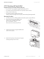
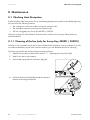
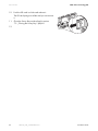
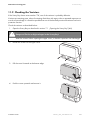
8.1.1 Cleaning of the fan (only for Sunny Boy 4000TL / 5000TL)
If the fan is only covered in loose dust, it can be cleaned with the help of a vacuum cleaner. If you do
not achieve satisfactory results with a vacuum cleaner, you can dismantle the fan for cleaning.
If the housing and fan are heavily soiled, proceed as follows:
1. Open the Sunny Boy as described in section 7.1 „Opening the Sunny Boy“ (46).
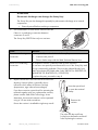
2. Wait for the fan to stop rotating.
3. Unlock and unplug the fan connection plug (A).
4. Push both latches of the fan (B) towards the fan and
remove the housing with the fan.
50
SB30TL_40TL_50TL-IEN085120
Installation Guide
SMA Solar Technology AG
Maintenance
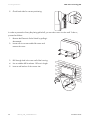
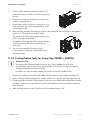
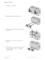
5. Push the upper and lower latches on the fan (C)
outwards and press the fan out of the housing from
the rear.
6. Clean the housing with a soft brush, a paint brush,
a cloth or compressed air.
7. Clean the fan with a soft brush, a paint brush, or a
cloth and water. Do not use compressed air as this
can damage the fan.
8. After cleaning, assemble everything in reverse order and close the Sunny Boy as described in
section 7.2 „Closing the Sunny Boy“ (48).
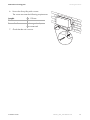
The arrows on the fan housing and on the fan must
point to the right on assembly.
The latches on the right of the fan housing must grip
under the housing wall when inserted into the
Sunny Boy.
9. The fan can be tested for function using a
communication component, as described in the
following section.
8.1.2 Testing the fan (only for Sunny Boy 4000TL / 5000TL)
Testing the Fan
You need a special data acquisition device (e.g. Sunny WebBox) or a PC with
corresponding software (e.g Sunny Data Control) to test the fan in order to be able to
change the parameters of the Sunny Boy.
In addition you also need the installer password to access the installer mode.
1. Request the installer password from the SMA Technical Service Line (contact: see Page 73).
2. Set the "CoolSys.FanTst" parameter in installer mode to "on" (using a communication device).
3. Check the air flow of the fan. The Sunny Boy sucks air in from underneath and then blows it back
out above. Listen for any unusual noise, which could indicate incorrect installation or that the
fans are faulty.
4. After checking the fan, set the "CoolSys.FanTst" parameter back to "off".
Installation Guide
SB30TL_40TL_50TL-IEN085120
51
Maintenance
SMA Solar Technology AG
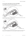
8.2 Inspection of the Electronic Solar Switch (ESS)
Check the Electronic Solar Switch for wear before plugging it in.
To do this, check the metal tongues on the inside of the plug for brown discoloration.
Metal tongues
If the metal tongues are brown or completely burned out (see figure below), then the Electronic Solar
Switch can no longer reliably disconnect the DC side.
Worn-out metal tongues
You must replace the handle of the Electronic Solar Switch before you can reactivate the Sunny Boy.
Replacements for damaged Electronic Solar Switch handles are available from your dealer.
52
SB30TL_40TL_50TL-IEN085120
Installation Guide
SMA Solar Technology AG
SD Card Slot
9 SD Card Slot
There are many applications for which the reading from an SD card is required:
• A firmware update is required for discussion with the SMA Technical Service Line.
SMA will send you a file with the firmware update via e-mail.
• You require adapted parameter settings for your installation location.
Request this from SMA Solar Technology. SMA will then send you an e-mail containing a file
with the corresponding settings and instructions on how to install them.
• Entering the Inst. code to unlock parameter sets (to allow you to configure a new country data
set via the rotary switches or change parameters). If necessary, you can request instructions for
the procedure from SMA Solar Technology, or they are sent with the required files.
Use an SD card with a maximum 2 GB of storage space.
Firmware Update
1. Save the required files onto the SD card in the following directory:
SD card drive:\UPDATE
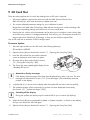
2. Open the Sunny Boy as described in section 7.1 „Opening the Sunny Boy“ (46).
3. Insert the SD card into the slot with the slanted
corner at the bottom until it locks into place.
4. Close the Sunny Boy as described in section
7.2 „Closing the Sunny Boy“ (48).
5. The Sunny Boy starts updating (the display shows
< Reading SD card >).
Anomalous display messages
If the display shows messages other than those displayed here, there is an error. The error
messages are described in section 10.2 „Error Messages“ (56) ordered by the event
number on the display.
6. < Update file ok > is shown on the display after the update file has been read successfully.
7. The update messages of the components in question are then displayed consecutively
(see section 10.1 „Update messages“ (55)).
Switching off the display
During the update, the display may be switched off for up to a minute (no display).
8. When the Sunny Boy has completed the update, < Update complete > is shown on the display
and you can remove the SD card again.
9. Open the Sunny Boy as described in section 7.1 „Opening the Sunny Boy“ (46).
Installation Guide
SB30TL_40TL_50TL-IEN085120
53
SD Card Slot
SMA Solar Technology AG
10. Push the SD card in a little and release it.
The SD card springs out a little and you can remove
it.
11. Close the Sunny Boy as described in section
7.2 „Closing the Sunny Boy“ (48).60
12.
54
SB30TL_40TL_50TL-IEN085120
Installation Guide
SMA Solar Technology AG
Messages
10 Messages
If there is no DC voltage, the display is blank.
Measurements can only be made and messages can only be displayed if there is sufficient
DC voltage (the green LED flashes or lights up).
10.1 Update messages
Corresponding display messages are shown in the scrolling text line of the display when an update
is made.
Display
< Inst.code valid >
Description
The Inst. code entered is valid.
The country data set configured is now unlocked
and can be changed.
< No new update on the SD card >
< Grid parameters not changed >
< The parameters were set successfully >
< Reading SD card >
< Setting parameters >
< Update complete >
< Bluetooth update >
< Display update >
< Main computer update >
< Communication update >
< RS485 module update >
< Language table update >
< Update file OK >
Installation Guide
If the country data set configured is protected, the
unlocking is only valid for max. 10 feed-in hours.
There is no update file relevant for this Sunny Boy
on the SD card, or the update present has
already been implemented.
The selected switch position is not assigned or
there is no country data set on the SD card.
A new country data set was configured.
The Sunny Boy is currently reading the SD card.
The Sunny Boy is setting the configured
parameters.
The Sunny Boy has completed the update
successfully.
The Bluetooth component was updated
successfully.
Successful update of the display.
The inverter component was updated
successfully.
The communication component was updated
successfully.
Successful update of the communication
interface.
Successful update of the language table.
The update file found is valid.
SB30TL_40TL_50TL-IEN085120
55
Messages
SMA Solar Technology AG
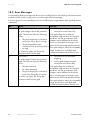
10.2 Error Messages
Corresponding display messages are shown in the scrolling text line of the display with relevant event
numbers. Knock on the housing cover to scroll through multi-line messages.
If an error persists for an extended period, the red LED begins to light and the fault signaling contact
is activated.
No.
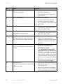
1
Cause
< Grid fault >
The grid voltage is above the permitted
range. This fault can have the following
causes:
• The grid voltage at the connection
point of the Sunny Boy is too high.
2
If the grid voltage lies outside the
acceptable range because of local grid
conditions, ask the grid operator if the
voltages can be adjusted at the feed-in
point, or if they agree to changes in the
values of the monitored operational limits.
• The grid impedance at the
connection point of the Sunny Boy is
If the grid voltage is within the acceptable
too high.
range, but the error is still displayed,
For reasons of safety, the Sunny Boy
contact the SMA Technical Service Line.
disconnects itself from the grid.
• Check the line circuit breaker
< Grid fault >
triggering.
The grid voltage is below the permitted
range. This fault can have the following
causes:
• Grid disconnected
• AC cable damaged
• The grid voltage at the connection
point of the Sunny Boy is too low
For reasons of safety, the Sunny Boy
disconnects itself from the grid.
56
Remedy
• Test the grid voltage and grid
connection on the Sunny Boy.
SB30TL_40TL_50TL-IEN085120
• Test the grid voltage and grid
connection to the Sunny Boy.
If the grid voltage lies outside the
acceptable range because of local grid
conditions, ask the grid operator if the
voltages can be adjusted at the feed-in
point, or if they agree to changes in the
values of the monitored operational limits.
If the grid voltage is within the acceptable
range, but the error is still displayed,
contact the SMA Technical Service Line.
Installation Guide
SMA Solar Technology AG
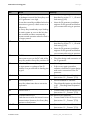
No.
3
4
5
Messages
Cause
< Grid fault >
Remedy
• Test the grid voltage at the
connection point of the Sunny Boy.
The average grid voltage over 10 minutes
is no longer within the permissible range. If, due to the local grid conditions, the grid
voltage exceeds the threshold configured,
This can be caused by the following:
ask the utility operator whether the voltage
• The grid voltage at the connection
at the feed-in point can be adjusted, or
point of the Sunny Boy is too high.
whether they agree to an alteration of the
• The grid impedance at the
threshold for voltage quality monitoring.
connection point of the Sunny Boy is
If the grid voltage is continually within the
too high.
acceptable range, but the error is still
The Sunny Boy disconnects to allow
displayed, contact the SMA Technical
compliance with the voltage quality of the Service Line.
grid.
< Grid fault >
• Check the grid connection for
extreme, short-term fluctuations in
The Sunny Boy is no longer in grid-parallel
frequency.
operation and has stopped feeding for
safety reasons.
< Grid fault >
• If possible, test the grid frequency
and the frequency of major
The grid frequency is outside the permitted
fluctuations.
range. For reasons of safety, the Sunny Boy
disconnects itself from the grid.
If repeated deviations occur and this is
causing these errors, ask the grid operator
if they agree to a modification of the
operating parameters.
6
< Grid fault >
The internal inverter monitoring has
detected an excessively high direct current
component in the grid current.
7
< Frequency impermissible >
Discuss the proposed parameters with the
SMA Technical Service Line.
• Check the grid connection for the DC
component.
• If this event occurs frequently, discuss
with the utility operator whether the
monitoring threshold can be raised.
• If possible, test the grid frequency
and the frequency of major
fluctuations.
The grid frequency is outside the permitted
range. For reasons of safety, the Sunny Boy
disconnects itself from the grid.
If repeated deviations occur and this is
causing these errors, ask the grid operator
if they agree to a modification of the
operating parameters.
Discuss the proposed parameters with the
SMA Technical Service Line.
Installation Guide
SB30TL_40TL_50TL-IEN085120
57
Messages
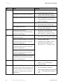
No.
8
9
SMA Solar Technology AG
Cause
< Grid Failure >
Wait for grid voltage
• Check AC installation.
< no PE connection >
• Check whether there is a general
power failure.
• Check AC installation.
10
< L and N swapped >
11
< Installation error >
Second phase connected to N.
33
< Unstable operation >
The supply at the DC input of the Sunny
Boy is not sufficient for stable operation.
34
< DC overvoltage >
The DC input voltage at the Sunny Boy is
too high.
35
Remedy
• Check fuse.
< Ground fault >
The Sunny Boy has detected a ground fault
in the PV generator.
• Connect the PE cable to the AC
terminal as described in section
5.2 „Connection to the Public Grid
(AC)“ (24).
• Correct the connection as described
in section 5.2 „Connection to the
Public Grid (AC)“ (24).
• Correct the connection as described
in section 5.2 „Connection to the
Public Grid (AC)“ (24).
• Wait for greater radiation.
• If this occurs again at medium
radiation, check the PV system design
and correct connection of the PV
generator.
• Disconnect the Sunny Boy from the PV
generator immediately as
described in section
7.1 „Opening the Sunny Boy“
(46)! Otherwise, the Sunny Boy
could be irreparably damaged!
• Check the DC voltage of the strings
to ensure that they comply with the
maximum input voltage of the Sunny
Boy before connecting the Sunny
Boy to the PV generator again.
• Check the strings for ground faults, as
described in section 11.1 „Ground
fault testing“ (62).
• Have the PV generator installation
engineer fix the ground fault before
you reconnect the string in question.
58
SB30TL_40TL_50TL-IEN085120
Installation Guide
SMA Solar Technology AG
No.
36
Cause
< High leakage current >
Remedy
• Check the strings for ground faults, as
described in section 11.1 „Ground
The leakage current of the Sunny Boy and
fault testing“ (62).
the PV generator is too high.
This can be caused by a sudden fault in the
connection to ground, a fault current or a
malfunction.
37
Messages
The Sunny Boy immediately stops feeding
the mains system as soon as the limit has
been reached and then automatically
resumes normal operation when the fault is
no longer present.
< Residual current excessive >
• Have the PV generator installation
engineer fix the ground fault before
you reconnect the string in question.
• Check the strings for ground faults, as
described in section 11.1 „Ground
fault testing“ (62).
• Have the PV generator installation
engineer fix the ground fault before
you reconnect the string in question.
If the event occurs frequently:
38
< DC Overcurrent >
39
Overcurrent occurs on the DC side of the
Sunny Boy and the Sunny Boy switches off.
< Wait for DC start conditions >
• Check the design and connection of
the PV generator.
• Wait for greater radiation.
The input power or voltage of the PV
modules is not yet sufficient for feeding into
the grid.
• If this occurs again at medium
radiation, check the PV system design
and correct connection of the PV
generator.
• Contact SMA Technical Service Line
(see section 15 „Contact“ (73)).
• Ensure ventilation is sufficient.
60 - 64
< Device error >
65
< overtemperature >
Sunny Boy deactivates due to excessive
temperature.
66
< Device error >
67
< communication lost >
68 - 70
A fault has occurred in the internal inverter
communication. However, the Sunny Boy
continues to feed power.
< Device error >
Installation Guide
• Check heat dissipation as described
in 8.1 „Checking Heat Dissipation“
(50).
• Contact SMA Technical Service Line
(see section 15 „Contact“ (73)).
If the event occurs frequently:
• Contact SMA Technical Service Line
(see section 15 „Contact“ (73)).
• Contact SMA Technical Service Line
(see section 15 „Contact“ (73)).
SB30TL_40TL_50TL-IEN085120
59
Messages
No.
71
SMA Solar Technology AG
Cause
< SD card defective >
Remedy
Re-format SD card.
< Parameter configuration unsuccessful >
• Re-save data onto the SD card.
• Copy the parameter file to the
directory SD card drive:\PARASET.
• Check parameters for valid values.
< Update file fault >
• Ensure that the Inst.Code is set to
authorize changes.
• Re-format SD card.
< Parameter file not found or defective >
< No update file found >
72
< Data cannot be saved >
73
Internal device fault, but the Sunny Boy
continues to feed power.
< Main computer update not successful >
Internal device fault.
< RS485I module update not successful >
Internal device fault, but the Sunny Boy
continues to feed power.
< Bluetooth update not successful >
• Re-save data onto the SD card.
• Copy the update file to the directory
SD card drive:\UPDATE.
• If the fault occurs frequently, contact
SMA Technical Service Line
(see section 15 „Contact“ (73)).
• Contact SMA Technical Service Line
(see section 15 „Contact“ (73)).
• Attempt update again.
• If the fault occurs again, contact
SMA Technical Service Line
(see section 15 „Contact“ (73)).
Internal device fault, but the Sunny Boy
continues to feed power.
< Display update not successful >
Internal device fault, but the Sunny Boy
continues to feed power.
< Language table update not successful >
74
Internal device fault, but the Sunny Boy
continues to feed power.
< Varistor fault >
80
< Derating pending >
The power output of the Sunny Boy was
reduced to below the nominal power for
more than 10 minutes due to excessive
temperatures.
60
SB30TL_40TL_50TL-IEN085120
• Check the varistors as described in
section 11.2 „Checking the
Varistors“ (63).
If the event occurs frequently:
• Ensure ventilation is sufficient.
• Check heat dissipation as described
in 8.1 „Checking Heat Dissipation“
(50).
Installation Guide
SMA Solar Technology AG
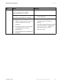
No.
90
Cause
< Inst.-Code invalid >
The Inst. code (personal installer
password) entered is not valid.
< Grid parameters locked >
The current country data set is locked.
< Waiting for main computer >
• The DC voltage at the DC input is not
sufficient to operate the main
computer.
• The selected rotary switch setting is
not assigned for the country
configuration.
Messages
Remedy
• Enter a valid Inst. code.
• Enter a valid Inst. code to change the
country data set.
• Ensure that sufficient DC voltage is
available (green LED lights or
flashes).
• Check the setting of the rotary switch
(see section 5.4.2 „Configuration
with rotary switches“ (38)).
• Enter Inst. code.
• The parameters to be changed are
protected.
Installation Guide
SB30TL_40TL_50TL-IEN085120
61
Troubleshooting
SMA Solar Technology AG
11 Troubleshooting
11.1 Ground fault testing
If the Sunny Boy displays event number "35", "36" or "37", there is probably a ground fault in the
PV generator.
Check the strings for ground faults as described below:
1. Open the Sunny Boy as described in section 7.1 „Opening the Sunny Boy“ (46).
2. Measure the voltages between the plus and minus
pole of a string against the ground potential.
If a voltage is present, there is a ground fault in the
corresponding string.
DANGER!
Lethal danger due to live PV generator!
• Do not touch the frame of the PV generator.
• Do not connect strings with ground faults to the Sunny Boy.
• Wait until no voltage can be measured.
The approximate position of the ground fault can be determined from the ratio of the measured
voltages between plus against ground potential and minus against ground potential.
Example:
In this case, the ground fault is between the second and third module.
3. Repeat step 2 for each string.
4. Close the Sunny Boy as described in section 7.2 „Closing the Sunny Boy“ (48).
62
SB30TL_40TL_50TL-IEN085120
Installation Guide
SMA Solar Technology AG
Troubleshooting
11.2 Checking the Varistors
If the Sunny Boy shows event number "74", one of the varistors is probably defective.
Varistors are wearing parts, whose functioning diminishes with age or due to repeated responses as
a result of overvoltage. It is therefore possible that one of the thermally monitored varistors has lost its
protective function.
Check the varistors as described below:
1. Open the Sunny Boy as described in section 7.1 „Opening the Sunny Boy“ (46).
DANGER!
Danger to life due to high voltages in the Sunny Boy!
Wait five minutes before opening the upper cover, so that the capacitors can discharge!
2. Loosen the screws on the upper cover.
3. Pull the cover forwards at the bottom edge.
4. Push the cover upwards and remove it.
Installation Guide
SB30TL_40TL_50TL-IEN085120
63
Troubleshooting
SMA Solar Technology AG
ATTENTION!
Electrostatic discharges can damage the Sunny Boy!
The Sunny Boy can be damaged irreparably by electrostatic discharge to its internal
components.
• Ground yourself before touching a component.
5. Use a Multimeter to check all the varistors and see
if there is a conducting connection between
connectors 2 and 3.
The Sunny Boy 3000TL has only two varistors.
Event
There is a conducting
connection.
There is no conducting
connection.
Measure
There is probably another fault in the Sunny Boy.
• Continue with point 9.
• Discuss further steps with the SMA Technical Service Line.
The respective varistor is defective and must be replaced.
The varistors are specially manufactured for use in the Sunny Boy and
are not commercially available. They must be ordered directly from
SMA Technologie AG (SMA order code: "SB-TV4" for SB3000TL-20,
"MSWR-TV8" for SB 4000TL-20 / 5000TL-20).
To replace the part, proceed to step 8.
6. Replace all varistors with new ones as shown in this
drawing. Varistor failure is generally due to
influences which affect all varistors similarly
(temperature, age, induced overvoltages).
If you do not receive a special tool for operating the
terminals together with your replacement varistors,
please contact SMA Solar Technology. As an
alternative, the terminal contacts can be operated
using a 3.5 mm wide screwdriver.
Ensure the varistor is installed the right way round!
Insert the special tool
to open the terminal
clamp
Remove the
varistor
The pole with the small loop
(crimp) must be fitted to terminal 1
when replacing the varistor.
64
SB30TL_40TL_50TL-IEN085120
Installation Guide
SMA Solar Technology AG
Troubleshooting
7. replace the cover upright.
8. Half tighten the screws with the washers.
9. Push the cover onto the housing until it clicks into
place above.
10. Secure the two cover screws with a torque of
2.4 Nm.
11. Close the lower cover and re-commission the Sunny
Boy as described in section 7.2 „Closing the
Sunny Boy“ (48).
Installation Guide
SB30TL_40TL_50TL-IEN085120
65
Decommissioning
SMA Solar Technology AG
12 Decommissioning
12.1 Disassembly
1. Open the Sunny Boy as described in section 7.1 „Opening the Sunny Boy“ (46).
2. Remove all connection cables from the Sunny Boy.
CAUTION!
Danger of burn injuries due to hot housing parts!
• Wait 30 minutes for the device to cool before dismantling it.
3. For top hat rail mounting: Loosen the screw between the housing and wall.
4. Open the safety lock if necessary.
5. Push the Sunny Boy to the left and remove it from the wall bracket or the top hat rail.
12.2 Replacement of the housing covers
In the event of faults, it can be the case that your Sunny Boy has to be replaced. In this case you will
receive a replacement device upon which transport covers are mounted.
Before you send your Sunny Boy back to SMA Solar Technology, you must replace the upper and
lower covers of your Sunny Boy with the transport covers.
1. Dismantle the Sunny Boy as described in section 12.1 „Disassembly“ (66).
2. Loosen the screws on the upper cover.
3. Pull the cover forwards at the bottom edge.
66
SB30TL_40TL_50TL-IEN085120
Installation Guide
SMA Solar Technology AG
Decommissioning
4. Push the cover upwards and remove it.
5. Remove the transport covers from the replacement
device in the same manner.
Now mount the transport covers of the replacement device onto your sunny Boy:
1. Install the cover upright.
2. Half tighten the screws with the washers.
3. Push the cover onto the housing until it clicks into
place above.
Installation Guide
SB30TL_40TL_50TL-IEN085120
67
Decommissioning
SMA Solar Technology AG
4. Secure the two cover screws with a torque of
2.4 Nm.
5. Secure the lower cover.
You can now send your Sunny Boy back to
SMA Solar Technology.
6. Secure the upper cover of your Sunny Boy onto the replacement device in the same manner.
7. Mount the replacement device again (see section 4.2 ) and connect (see section 5 ).
12.3 Packaging
If possible, please pack the Sunny Boy in the original packaging.
If this is no longer available, you can also use an equivalent carton that fulfills the following
requirements:
• Suitable for loads of at least 25 kg
• With handle system
• Can be closed fully
12.4 Storage
Store the Sunny Boy in a dry place where ambient temperatures are always between
-25 °C and +60 °C.
12.5 Disposal
Dispose of the Sunny Boy at the end of its service life in accordance with the disposal regulations for
electronic scrap which apply at the installation site at that time. Alternatively, send it back to SMA
Solar Technology with shipping paid by sender, and labeled "ZUR ENTSORGUNG" ("for disposal")
(contact see Page 73).
68
SB30TL_40TL_50TL-IEN085120
Installation Guide
SMA Solar Technology AG
Technical Data
13 Technical Data
SB 3000TL-20 SB 4000TL-20 SB 5000TL-20
PV generator connection data
Max. input voltage
Input voltage, MPP range
Max. input current
Max. input power
Number of MPP trackers
Max. number of strings (parallel)
Voltage ripple
Operating consumption
a)
UDC max
UPV
IPV max
PDC
Uss
The maximum open circuit voltage, which can occur at a cell temperature of -10 °C, may not exceed the maximum input
voltage.
Grid Connection Data
Nominal output power
Max. output power
Nominal output current
(at 230 V AC)
Max. output current
Max. fuse protection
Harmonic distortion of output current
PACnom
3000 W
4000 W
PACmax
IACnom
3000 W
13 A
4000 W
17.4 A
IACMax
16 A
22 A
32 A
<4%
KIAC
PAC > 0.5 PACnom)
Nominal AC voltage
Operating range
AC grid frequency
Operating range
Power factor
(at nominal output power)
Overvoltage category
Test voltage (50 Hz)
Test surge voltage
Internal consumption at night
4600 W /
5000 Wb)
5000 W
20 A
22 A
< 3 % at PACNom)
(at KUgrid < 2 %,
b)
550 V a)
125 V DC ... 440 V DC
17 A
2 x 15 A
3200 W
4200 W
5300 W
1
2
2
2x2
< 10 % of the input voltage
< 10 W
UACnom
UAC
fACnom
fAC
cos phi
220 V, 230 V, 240 V
180 V - 280 Vb)
50 Hz, 60 Hz / ± 5 Hz
45 – 65 Hzb)
1
III
1.4 kV (1 s routine testing / 5 s type testing)
4 kV (serial interface: 6 kV)
< 0.5 W
depending on country configuration
Installation Guide
SB30TL_40TL_50TL-IEN085120
69
Technical Data
SMA Solar Technology AG
SB 3000TL-20 SB 4000TL-20 SB 5000TL-20
General Data
EC Declaration of Conformity
Dimensions (w x h x d)
Weight
Protection rating in accordance with
DIN EN 60529
enclosed set of documents,
download area www.SMA.de
approx. 470 mm x 445 mm x 180 mm
approx. 25 kg
IP 65 Electronics
Connection area: IP 54
Climatic conditions according to DIN EN 50178:1998-04:
Installation type C:
class 4K4H
extended temperature range:
-25 °C to +60 °C
extended air humidity range:
0 ... 100 %
extended air pressure range:
Transport type E:
Operating temperature range
Max. operating altitude
Topology
Protection class
Protective function DC side
All-pole disconnection unit on the DC side
Surge protection
Personal protection
79.5 kPa to 106 kPa
class 2K3
temperature range:
-25 °C ... +70 °C
-25 °C ... +60 °C
2000 m above sea level NN
transformerless
I
Electronic Solar Switch,
DC plug connector
thermally monitored varistors
insulation monitoring
(Riso 1 M Ohm)
Pole Confusion Protection
70
SB30TL_40TL_50TL-IEN085120
integrated all-pole sensitive leakage current
monitoring unit
via short-circuit diode
Installation Guide
SMA Solar Technology AG
Technical Data
SB 3000TL-20 SB 4000TL-20 SB 5000TL-20
Protective function AC Side
Short circuit proof
All-pole disconnection unit on grid side
current control
Automatic disconnection device
(SMA grid guard 3)
Efficiency
max. efficiency
European standard efficiency
eta max
eta euro
Communication interfaces
Bluetooth
RS485 (galvanically isolated)
Electronic Solar Switch (ESS)
Electrical service life
(in case of a short circuit, with a nominal current
of 35 A)
Maximum switching current
Maximum switching voltage
Maximum PV power
Protection rating when plugged in
Protection rating when unplugged
96.3 %
97.0 %
96.2 %
96.5 %
as standard
optional
min. 50 switching processes
35 A
800 V
approx. 12 kW
IP65
IP21
Efficiency curve
Installation Guide
SB30TL_40TL_50TL-IEN085120
71
Accessories
SMA Solar Technology AG
14 Accessories
In the following overview you will find the relevant accessories and replacement parts for your
product. When necessary, you can procure these from SMA Solar Technology or from your dealer.
Designation
Brief Description
Replacement varistors
Set of thermally
monitored varistors
Electronic Solar Switch ESS-HANDLE:05
handle as replacement
part
RS485 interface
DM-485CB-10
ESS handle
RS485 upgrade kit
72
SB30TL_40TL_50TL-IEN085120
SMA order number
SB 3000TL-20
SB 4000TL-20
SB 5000TL-20
SB-TV4 ( 2 units)
MSWR-TV8 (3 units)
ESS-HANDLE:05
DM-485CB-10
Installation Guide
SMA Solar Technology AG
Contact
15 Contact
If you have technical problems concerning our products, please contact the SMA Service Line We
require the following information in order to provide you with the necessary assistance:
• Inverter Type
• Series number of the Sunny Boy
• Type and number of modules connected
• Event number or display of the Sunny Boy
• type of communication, if applicable
• Type of fault signaling contact connected, if applicable
SMA Solar Technology AG
Sonnenallee 1
D34266 Niestetal, Germany
www.SMA.de
SERVICE LINE
Inverter:
+49 561 9522 1499
Communication: +49 561 9522 2499
SMS-Callback: +49 176 888 222 44
Fax:
+49 561 9522 4699
[email protected]
Installation Guide
SB30TL_40TL_50TL-IEN085120
73
Contact
74
SMA Solar Technology AG
SB30TL_40TL_50TL-IEN085120
Installation Guide
SMA Solar Technology AG
Legal Restrictions
The information contained in this document is the property of SMA Solar Technology AG. Publishing its content, either partially or
in full, requires the written permission of SMA Solar Technology AG. Any internal company copying of the document for the
purposes of evaluating the product or its correct implementation is allowed and does not require permission.
Exclusion of liability
The general terms and conditions of delivery of SMA Solar Technology AG shall apply.
The content of these documents is continually checked and amended, where necessary. However, discrepancies cannot be
excluded. No guarantee is made for the completeness of these documents. The latest version is available online at www.SMA.de
or from the usual sales channels.
Guarantee or liability claims for damages of any kind are excluded if they are caused by one or more of the following:
• Damages during transportation
• Improper or inappropriate use of the product
• Operating the product in an unintended environment
• Operating the product whilst ignoring relevant, statutory safety regulations in the deployment location
• Ignoring safety warnings and instructions contained in all documents relevant to the product
• Operating the product under incorrect safety or protection conditions
• Altering the product or supplied software without authority
• The product malfunctions due to operating attached or neighboring devices beyond statutory limit values
• In case of unforeseen calamity or force majeure
The use of supplied software produced by SMA Solar Technology AG is subject to the following conditions:
• SMA Solar Technology AG rejects any liability for direct or indirect damages arising from the use of software developed by
SMA Solar Technology AG. This also applies to the provision or non-provision of support activities.
• Supplied software not developed by SMA Solar Technology AG is subject to the respective licensing and liability agreements
of the manufacturer.
SMA Factory Warranty
The current guarantee conditions come enclosed with your device. These are also available online at www.SMA.de and can be
downloaded or are available on paper from the usual sales channels if required.
Trademarks
All trademarks are recognized even if these are not marked separately. Missing designations do not mean that a product or brand
is not a registered trademark.
SMA Solar Technology AG
Sonnenallee 1
34266 Niestetal
Germany
Tel. +49 561 9522-0
Fax +49 561 9522-100
www.SMA.de
E-Mail: [email protected]
© 2004 to 2008 SMA Solar Technology AG. All rights reserved
Installation Guide
SB30TL_40TL_50TL-IEN085120
75
SMA Solar Technology AG
www.SMA.de
Sonnenallee 1
34266 Niestetal, Germany
Tel.: +49 561 9522 4000
Fax: +49 561 9522 4040
E-Mail: [email protected]
Freecall: 0800 SUNNYBOY
Freecall: 0800 78669269