1
PV Inverters
SUNNY BOY 1100 / 1200 / 1700
Installation Guide
SB11_12_17-IEN094131 | IMEN-SB11_17 | Version 3.1
EN
SMA Solar Technology AG
Table of Contents
Table of Contents
1
1.1
1.2
1.3
1.4
Notes on this Manual. . . . . . . . . . . . . . . . . . . . . . . . . . . . . .
Area of Validity. . . . . . . . . . . . . . . . . . . . . . . . . . . . . . . . . . . . . .
Target Group . . . . . . . . . . . . . . . . . . . . . . . . . . . . . . . . . . . . . . .
Additional Information . . . . . . . . . . . . . . . . . . . . . . . . . . . . . . . .
Symbols Used . . . . . . . . . . . . . . . . . . . . . . . . . . . . . . . . . . . . . . .
2
2.1
2.2
Security . . . . . . . . . . . . . . . . . . . . . . . . . . . . . . . . . . . . . . . . . 7
Appropriate Usage . . . . . . . . . . . . . . . . . . . . . . . . . . . . . . . . . . . 7
Safety Instructions . . . . . . . . . . . . . . . . . . . . . . . . . . . . . . . . . . . . 9
3
3.1
3.2
Unpacking. . . . . . . . . . . . . . . . . . . . . . . . . . . . . . . . . . . . . . 10
Packing List . . . . . . . . . . . . . . . . . . . . . . . . . . . . . . . . . . . . . . . . 10
Identifying the Sunny Boy . . . . . . . . . . . . . . . . . . . . . . . . . . . . . 10
4
4.1
4.2
Installing the Device . . . . . . . . . . . . . . . . . . . . . . . . . . . . . . 11
Selecting the Mounting Location. . . . . . . . . . . . . . . . . . . . . . . . 11
Mounting the Sunny Boy with a Wall Mounting Bracket . . . . . 13
5
5.1
Electrical Connection . . . . . . . . . . . . . . . . . . . . . . . . . . . . . 15
Overview of the Connection Area . . . . . . . . . . . . . . . . . . . . . . 15
5.1.1
Exterior View . . . . . . . . . . . . . . . . . . . . . . . . . . . . . . . . . . . . . . . . . . . . . . . . . 15
5.1.2
Interior View . . . . . . . . . . . . . . . . . . . . . . . . . . . . . . . . . . . . . . . . . . . . . . . . . 16
5.2
5.3
5.4
5.5
5.6
Connecting the Sunny Boy to the public grid (AC) . . . . . . . . . . 17
Setting the Display Language . . . . . . . . . . . . . . . . . . . . . . . . . . 22
Communication. . . . . . . . . . . . . . . . . . . . . . . . . . . . . . . . . . . . . 22
Connecting the PV Generator (DC) . . . . . . . . . . . . . . . . . . . . . 23
Setting the installation country . . . . . . . . . . . . . . . . . . . . . . . . . 25
6
6.1
Commissioning the Sunny Boy . . . . . . . . . . . . . . . . . . . . . 26
Display . . . . . . . . . . . . . . . . . . . . . . . . . . . . . . . . . . . . . . . . . . . 27
Installation Guide
SB11_12_17-IEN094131
5
5
5
5
6
3
Table of Contents
SMA Solar Technology AG
6.2
Blink Codes. . . . . . . . . . . . . . . . . . . . . . . . . . . . . . . . . . . . . . . . 29
7
7.1
7.2
Opening and Closing. . . . . . . . . . . . . . . . . . . . . . . . . . . . . 32
Opening the Sunny Boy . . . . . . . . . . . . . . . . . . . . . . . . . . . . . . 32
Closing the Sunny Boy . . . . . . . . . . . . . . . . . . . . . . . . . . . . . . . 33
8
8.1
Maintenance and Cleaning . . . . . . . . . . . . . . . . . . . . . . . . 35
Check the Electronic Solar Switch for wear . . . . . . . . . . . . . . . 35
9
9.1
Troubleshooting . . . . . . . . . . . . . . . . . . . . . . . . . . . . . . . . . 36
The red LED is continuously on . . . . . . . . . . . . . . . . . . . . . . . . . 36
9.1.1
Checking the PV Generator for Ground Fault . . . . . . . . . . . . . . . . . . . . . . . . 36
9.1.2
Checking the Function of the Varistors . . . . . . . . . . . . . . . . . . . . . . . . . . . . . 38
10
10.1
10.2
10.3
10.4
Decommissioning . . . . . . . . . . . . . . . . . . . . . . . . . . . . . . . . 40
Removing the Sunny Boy . . . . . . . . . . . . . . . . . . . . . . . . . . . . . 40
Packaging the Sunny Boy . . . . . . . . . . . . . . . . . . . . . . . . . . . . . 41
Storing the Sunny Boy. . . . . . . . . . . . . . . . . . . . . . . . . . . . . . . . 41
Disposing of the Sunny Boy . . . . . . . . . . . . . . . . . . . . . . . . . . . 41
11
Technical Data . . . . . . . . . . . . . . . . . . . . . . . . . . . . . . . . . . 42
12
Accessories . . . . . . . . . . . . . . . . . . . . . . . . . . . . . . . . . . . . . 46
13
Contact . . . . . . . . . . . . . . . . . . . . . . . . . . . . . . . . . . . . . . . . 47
4
SB11_12_17-IEN094131
Installation Guide
SMA Solar Technology AG
Notes on this Manual
1 Notes on this Manual
This manual describes how to mount, install, commission and service the Sunny Boy 1100 (SB 1100),
Sunny Boy 1200 (SB 1200) and Sunny Boy 1700 (SB 1700).
Store this manual where it can be accessed at all times.
1.1 Area of Validity
This manual applies to the following SMA inverters:
• Sunny Boy 1100 (discontinued model),
• Sunny Boy 1200 (available on request),
• Sunny Boy 1700.
1.2 Target Group
This manual is for qualified personnel. The tasks described in this manual may only be performed by
qualified personnel.
1.3 Additional Information
You will find further information on special topics such as designing a line circuit breaker or the
description of the operating parameters in the download area at www.SMA.de/en.
Refer to the user manual for detailed information on troubleshooting and operating the Sunny Boy.
Installation Guide
SB11_12_17-IEN094131
5
Notes on this Manual
SMA Solar Technology AG
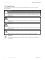
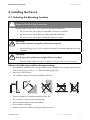
1.4 Symbols Used
The following types of safety instructions and general information appear in this document as
described below:
DANGER!
G
DANGER indicates a hazardous situation which, if not avoided, will result in death or
serious injury.
WARNING!
WARNING indicates a hazardous situation which, if not avoided, could result in death or
serious injury.
CAUTION!
CAUTION indicates a hazardous situation which, if not avoided, could result in minor or
moderate injury!
NOTICE!
NOTICE indicates a situation that can result in property damage if not avoided.
Information
Information provides tips that are valuable for the optimal installation and operation of
your product.
6
SB11_12_17-IEN094131
Installation Guide
SMA Solar Technology AG
Security
2 Security
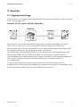
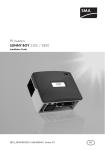
2.1 Appropriate Usage
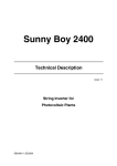
The Sunny Boy is a PV inverter, which converts the DC current of the PV generator to AC current and
feeds it into the public grid.
Principle of a PV system with this Sunny Boy
The Sunny Boy may only be operated with PV generators (modules and cabling) of protection
class II. Do not connect any sources of energy other than PV modules to the Sunny Boy.
When designing the PV system, ensure that the values comply with the permitted operating range of
all components at all times. The free design program "Sunny Design"
(www.SMA.de/en/SunnyDesign) will assist you. The manufacturer of the PV modules must have
approved the modules for use with this Sunny Boy. You must also ensure that all measures
recommended by the module manufacturer for long-term maintenance of the module properties are
taken (see also Technical Information "Module Technology", in the download area of
www.SMA.de/en).
Do not use the Sunny Boy for purposes other than those described here. Alternative uses,
modifications to the Sunny Boy or the installation of components not expressly recommended or sold
by the manufacturer void the warranty claims and operation permission.
Installation Guide
SB11_12_17-IEN094131
7
Security
SMA Solar Technology AG
Certified Countries
The Sunny Boy 1100 / 1200 / 1700 (with according configuration) fulfill the requirements specified
in the following standards and directives (dated: July/2009):
• VDE 0126-1-1 (02.2006)
• G83/1 (09.2003)
• CER/06/190 (10.2006)
• E 2750 (11.2004)
• PPC (06.2006)
• EN 50438 (12.2007)
• C10/C11 (08.2003)
• AS4777 (2005)
• MEA
• IEC-utility Meeting 216
SMA Solar Technology can preset special grid parameters for other countries / installation locations
according to customer request, after evaluation by SMA Solar Technology.
You can later make modifications yourself by changing software parameters with respective
communication products (e.g. Sunny Data Control). A personal password is required for this, which
you can obtain from the Serviceline upon request.
8
SB11_12_17-IEN094131
Installation Guide
SMA Solar Technology AG
Security
2.2 Safety Instructions
DANGER!
Danger to life due to high voltages in the Sunny Boy!
• All work on the Sunny Boy must only be carried out by qualified personnel.
CAUTION!
Parts of the enclosure can get hot - Risk of burn injuries!
• Do not touch the enclosure of the Sunny Boy during operation.
NOTICE!
Foreign objects or water entering the Sunny Boy can damage the device!
Once the Electronic Solar Switch has been pulled out, the Sunny Boy only provides
protection rating IP21. The Sunny Boy is then no longer protected against water and
contamination with dirt!
In order that the protection rating IP65 is also provided during a temporary
decommissioning, proceed as follows:
• Unplug all DC plug connectors and seal them with the protecting caps provided.
• Attach the Electronic Solar Switch again.
Grounding the PV generator
Comply with the local requirements for grounding the modules and the PV generator. SMA
Solar Technology recommends to electrically bond the module frames, the racks and all
metal surfaces and ground these in order to have optimal protection of the system and
personnel.
Installation Guide
SB11_12_17-IEN094131
9
Unpacking
SMA Solar Technology AG
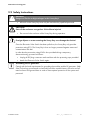
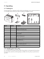
3 Unpacking
3.1 Packing List
Check the delivery for completeness and for visible external damage, such as cracks in the enclosure
or in the display. Please contact your dealer if something is damaged or missing.
Object
A
B
C
D
E
F
G
H
I
J
K
L
M
N
O
P
Quantity
1
1
1
1
2
1
1
1
1
1
1
2
1
1
2
1
Description
Sunny Boy
Wall mounting bracket
Electronic Solar Switch (ESS)
Set of documents
1 installation guide, 1 user manual
Socket element
Threaded sleeve
Pressure screw PG13.5
Sealing ring PG13.5
Fastening case PG13.5
Cable gland PG16
Protecting caps for DC connector
Protective cap for AC screw clamp
M6x12 cylinder head screw
Plastic washer M5 (replacement for lid)
Jumper
3.2 Identifying the Sunny Boy
You can identify the Sunny Boy by the type plate. The type plate is on the right side of the enclosure.
The serial number (serial No.) and the type (Type / Model) of the Sunny Boy are specified on the
type plate.
10
SB11_12_17-IEN094131
Installation Guide
SMA Solar Technology AG
Installing the Device
4 Installing the Device
4.1 Selecting the Mounting Location
DANGER!
Danger to life due to fire or explosion!
Despite careful construction, a fire can occur with electrical devices.
• Do not mount the Sunny Boy on flammable construction materials.
• Do not mount the Sunny Boy near highly flammable materials.
• Do not mount the Sunny Boy in potentially explosive areas.
CAUTION!
Parts of the enclosure can get hot - Risk of burn injuries!
• Mount the Sunny Boy in such a way that it cannot be touched inadvertently during
operation.
CAUTION!
Risk of injury due to the heavy weight of the Sunny Boy!
• Take the weight of the Sunny Boy of approx. 25 kg into account for mounting.
Observe the following conditions during mounting:
• The installation method and mounting location must be suitable for the weight and dimensions
of the Sunny Boy (see section 11 "Technical Data" (page 42)).
• Mount on a solid surface.
• The installation location must be accessible at all times.
• Vertical installation or tilted backwards by max. 45°.
• The connection area must point downwards.
• Never install the device with a forward tilt.
• Do not install horizontally.
• Install at eye level to allow operating modes to be read.
Installation Guide
SB11_12_17-IEN094131
11
Installing the Device
SMA Solar Technology AG
• The ambient temperature should be below 40 °C to ensure optimal operation.
• The Sunny Boy must be easy to remove from the mounting location at any time.
• Do not expose the Sunny Boy to direct sunlight, so as to avoid power reduction due to excessive
heating.
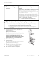
• In a living area, do not mount the unit on
plasterboard walls (or similar) in order to avoid
audible vibrations.
The Sunny Boy can make noises when in use which
can be regarded as a nuisance when installed in a
living area.
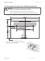
• Observe the minimum clearances to walls, other
inverters or objects as shown in the diagram in
order to guarantee sufficient heat dissipation and to
have enough space for removing the Electronic
Solar Switch.
12
SB11_12_17-IEN094131
Installation Guide
SMA Solar Technology AG
Installing the Device
4.2 Mounting the Sunny Boy with a Wall Mounting Bracket
CAUTION!
Risk of injury due to the heavy weight of the Sunny Boy!
• Take the weight of the Sunny Boy of approx. 25 kg into account.
• When mounting the bracket, use fastening material suitable for the material.
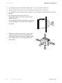
1. Use the wall mounting bracket as a drilling template and mark the position of the drill holes.
2. Attach the wall mounting bracket to the wall using
appropriate screws and washers.
Installation Guide
SB11_12_17-IEN094131
13
Installing the Device
SMA Solar Technology AG
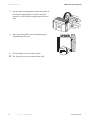
3. Use the upper mounting clips to fit the Sunny Boy in
the wall mounting bracket so that it cannot be
pushed out of the wall mounting bracket from the
side.
4. Secure the Sunny Boy in position fastening the
supplied M6x12 screw.
5. Check that the unit is securely in place.
☑ The Sunny Boy is now mounted on the wall.
14
SB11_12_17-IEN094131
Installation Guide
SMA Solar Technology AG
Electrical Connection
5 Electrical Connection
NOTICE!
Electrostatic discharges can damage the Sunny Boy!
Internal components of the Sunny Boy can be irreparably damaged by static discharge.
• Ground yourself before touching a component.
5.1 Overview of the Connection Area
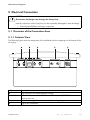
5.1.1 Exterior View
The following figure shows the assignment of the individual enclosure openings on the bottom of the
Sunny Boy.
Object
A
B
C
D
Installation Guide
Description
Plug connectors for connecting the PV strings
Socket for the connection of the Electronic Solar Switch (ESS) DC load
disconnection unit
Cable feed-through for communication (with sealing plugs)
Plug for AC connection
SB11_12_17-IEN094131
15
Electrical Connection
SMA Solar Technology AG
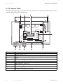
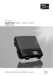
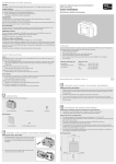
5.1.2 Interior View
The following diagram gives a schematic overview of the various components and connection points
inside the Sunny Boy with the lid removed:
Object
A
B
C
D
E
F
G
H
I
16
Description
Varistors, section 9.1.2 Connection area and sockets for communication (RS485, radio), section 5.4 Display
PE (protective earth) connecting cable for cover
Operating status LEDs
Plug socket (AC), section 5.2 Tab for grounding the cable shield with RS485 communication
PV input plugs (DC), section 5.5 Electronic Solar Switch (ESS) socket
SB11_12_17-IEN094131
Installation Guide
SMA Solar Technology AG
Electrical Connection
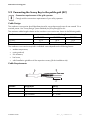
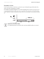
5.2 Connecting the Sunny Boy to the public grid (AC)
Connection requirements of the grid operator
Comply with the connection requirements of your utility operator.
Cable Design
The conductor cross-section should be dimensioned in a way that output losses do not exceed 1% at
nominal power. Use "Sunny Design" (www.SMA.de/en/SunnyDesign) for this.
The maximum cable lengths relative to the conductor cross-section are shown in the following table.
Conductor cross-section
SB 1100
21 m
35 m
1.5 mm²
2.5 mm²
Maximum cable length
SB 1200
18 m
30 m
SB 1700
15 m
22.5 m
The conductor cross-section required in individual cases depends on the following factors:
• ambient temperature,
• routing method,
• UV resistance,
• line losses,
• valid installation guidelines of the respective country (of the installation site).
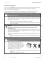
Cable Requirements
Position
A
B
C
Installation Guide
Designation
External diameter
Conductor cross-section
Strip insulation
Value
9 ...17 mm
max. 2.5 mm²
4 ... 5 mm
SB11_12_17-IEN094131
17
Electrical Connection
SMA Solar Technology AG
Load Disconnection Unit
You must install a separate line circuit breaker for each inverter in order to ensure that the inverter
can be securely disconnected under load. The maximal permissible rating is located in
section 11 "Technical Data" (page 42)
Detailed information and examples for the design of a line circuit breaker can be found in the
Technical Information "Line Circuit Breaker" in the download area of www.SMA.de/en.
DANGER!
Danger to life due to fire!
When more than one inverter is connected to the same line circuit breaker, the protective
function of the line circuit breaker is no longer guaranteed. It can result in a cable fire or
the destruction of the inverter.
• Never connect several inverters to a single line circuit breaker.
• Comply with the maximum permissible fuse protection of the inverter when selecting
the line circuit breaker.
NOTICE!
Damaging of the Sunny Boy by using screw type fuse elements as load
disconnection unit!
A screw type fuse element, e.g. D system (Diazed) or D0 system (Neozed) is not a circuit
breaker, and may not be used as a load disconnection unit. A screw type fuse element is
only used as cable protection.
When disconnecting under load using a screw type fuse element, the Sunny Boy can be
damaged.
• Use only a load disconnecting switch or a line circuit breaker as load disconnecting
unit.
DANGER!
Danger to life due to fire!
When a generator (Sunny Boy) and a
consumer are connected to the same line
circuit breaker, the protective function of the
line circuit breaker is no longer guaranteed.
The current from the Sunny Boy and the grid
can add up to overcurrent which is not
detected by the line circuit breaker.
• Never connect loads between the Sunny Boy and the line circuit breaker without
protection.
• Always install separate fuses for loads.
18
SB11_12_17-IEN094131
Installation Guide
SMA Solar Technology AG
Electrical Connection
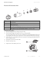
Overview AC connection socket
Object
A
B
C
D
E
F
Description
Socket element
Threaded sleeve
Sealing ring PG13.5
Fastening case PG13.5
Pressure screw for PG13.5 (for cable diameters between 9 and 13.5 mm)
Cable gland PG16 (for cable diameters between 13.5 and 17 mm)
Connection Procedure
1. Choose an appropriate screw fitting for the AC cable.
2. Check the grid voltage and compare it with "VAC" on the type plate.
The exact working range of the Sunny Boy is specified in the operating parameters. These can
be uploaded via a communication component or can be ordered from SMA Solar Technology.
3. Switch off the line circuit breaker and secure it to prevent it from being reactivated and ensure
that no voltage is present.
4. Strip approx. 30 mm from the AC cable.
5. Shorten L and N by 5 mm.
6. Strip the wires of the cable by 4 to 5 mm.
Installation Guide
SB11_12_17-IEN094131
19
Electrical Connection
SMA Solar Technology AG
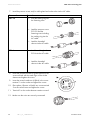
7. Lead the pressure screw and/or cable gland and socket tube via the AC cable.
Size used
PG13.5
Procedure
• Push the sealing ring into
the fastening case.
• Lead the pressure screw
PG13.5 and the
fastening case including
the sealing ring via the
AC cable.
• Lead the threaded
sleeve via the AC cable.
PG16
• Lead the cable gland
PG16 via the AC cable.
• Lead the threaded
sleeve via the AC cable.
8. Insert the protective earth PE (green-yellow) in the
screw terminal with the earth sign on the socket
element and tighten the screw.
9. Insert the neutral conductor N (blue) in the screw
terminal 1 on the socket and tighten the screw.
10. Place phase L (brown or black) into screw terminal
2 on the socket insert and tighten the screw.
11. Terminal 3 on the socket element remains unused.
12. Make sure the wires are securely connected.
20
SB11_12_17-IEN094131
Installation Guide
SMA Solar Technology AG
Electrical Connection
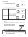
13. Screw the threaded sleeve onto the socket element.
14. Screw the pressure screw tightly onto the threaded
sleeve.
Size used
PG13.5
Procedure
The fastening case along with the sealing ring is pressed into the threaded
sleeve and can no longer be seen.
PG16
☑ AC connection socket has been screwed together.
15. Seal the socket element with the provided protecting cap if the Sunny Boy is not immediately
connected.
16. Insert the AC connection socket into the AC socket on the Sunny Boy. If necessary, remove the
protective cap beforehand.
17. Screw the AC connection socket's threaded ring
tightly onto the AC socket on the Sunny Boy. The
threaded ring acts as a seal and a cable grip for the
AC connection socket.
☑ The AC cable is connected to the Sunny Boy.
DANGER!
Danger to life due to high voltages in the Sunny Boy!
• Do not switch on the line circuit breaker until the Sunny Boy is securely closed and
the PV generator has been connected.
Installation Guide
SB11_12_17-IEN094131
21
Electrical Connection
SMA Solar Technology AG
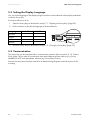
5.3 Setting the Display Language
You can set the language of the display using the switches on the underside of the display assemblies
inside the Sunny Boy.
Proceed as follows to do so:
1. Open the Sunny Boy as described in section 7.1 "Opening the Sunny Boy" (page 32).
2. Set the switches to the desired language as illustrated below.
Language
German
English
French
Spanish
Switch S2
B
B
A
A
Switch S1
B
A
B
A
3. Close the Sunny Boy as described in section 7.2 "Closing the Sunny Boy" (page 33).
5.4 Communication
The Sunny Boy can be equipped with a communication interface (slot see section 5.1.2 "Interior
View" (page 16)) in order to communicate with special data acquisition devices (e. g. Sunny
WebBox) or a PC with appropriate software (e.g. Sunny Data Control).
See the communication interface manual for a detailed wiring diagram and a description of the
mounting.
22
SB11_12_17-IEN094131
Installation Guide
SMA Solar Technology AG
Electrical Connection
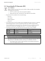
5.5 Connecting the PV Generator (DC)
Use of Adaptors
Adaptors (branch connectors) are not to be visible or freely accessible in the immediate
surrounding of the Sunny Boy.
• The DC current flow may not be interrupted via adaptors.
• Always disconnect the current flow first via the Electronic Solar Switch.
• Requirements for the modules of the connected strings:
– same type
– same number
– identical alignment
– identical tilt
• The connecting wires of the PV modules must be equipped with plug connectors in order that
these DC plug connectors can be connected to the DC input sockets of the Sunny Boy.
A pre-assembled set for connecting the free cable ends of a string is available as optional
accessory from SMA Solar Technology (see section 12 "Accessories" (page 46)).
• The following limit values at the DC input of the Sunny Boy may not be exceeded:
Sunny Boy
SB 1100
SB 1200
SB 1700
Maximum input voltage
400 V (DC)
400 V (DC)
400 V (DC)
Maximum input current
10 A (DC)
12.6 A (DC)
12.6 A (DC)
DANGER!
Risk of lethal electric shock or fire!
The maximum possible input current per string is limited by the plug connectors used. If the
plug connector is overloaded, an electric arc may occur and there is a fire risk.
• Ensure that the input current for each string does not exceed the maximum flow
current of the plug connectors used.
Installation Guide
SB11_12_17-IEN094131
23
Electrical Connection
SMA Solar Technology AG
Connection Procedure
DANGER!
Danger to life due to high voltages in the Sunny Boy!
• Before connecting the PV generator, ensure that the line circuit breaker is switched
off.
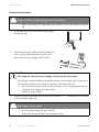
1. Pull the Electronic Solar Switch downwards, slightly
towards the wall.
2. Check the connection cables of the PV modules for
correct polarity and compliance with the Sunny
Boy's maximum input voltage of 400 V (DC).
NOTICE!
Exceeding the maximum input voltage can destroy the Sunny Boy!
If the voltage of the PV modules exceeds the maximum input voltage of the Sunny Boy, it
can be destroyed by the overvoltage. All warranty claims become void.
• Do not connect strings to the Sunny Boy with open circuit voltage greater than the
maximum input voltage of the Sunny Boy.
• Check the system design.
3. Check the strings for ground faults, as described in section 9.1.1 "Checking the PV Generator
for Ground Fault" (page 36).
DANGER!
Risk of lethal electric shock!
• Do not connect strings with ground faults.
• Firstly, clear the ground fault in the respective string.
24
SB11_12_17-IEN094131
Installation Guide
SMA Solar Technology AG
Electrical Connection
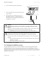
4. Connect faultless strings of the PV generator.
5. Close unused DC input sockets with the protective
caps provided.
6. Check the Electronic Solar Switch for wear, as
described in section 8.1 "Check the Electronic
Solar Switch for wear" (page 35), and attach until
it audibly locks into place.
NOTICE!
Manipulating the connector in the handle can damage the Electronic Solar
Switch!
The connector within the handle must remain movable in order to ensure proper contact.
Tightening the screw voids all warranty claims and creates a fire risk.
• Do not tighten the connector screw in the Electronic Solar Switch handle.
NOTICE!
The Electronic Solar Switch can be damaged if it is inserted incorrectly!
The Electric Solar Switch can be damaged by high voltages if it has not been attached
properly.
• Press the handle firmly into place on the socket of the Electronic Solar Switch until it
audibly locks into place.
• Check that the handle is securely in place.
☑ The PV generator is now connected.
5.6 Setting the installation country
Using the "Default" parameter you can set the installation country and/or the grid connection
standard valid for the country via a communication device (e.g. Sunny WebBox) or a PC with
appropriate software (e.g. Sunny Data Control). However, this is only required if the Sunny Boy was
originally ordered for another country. The standard to which the Sunny Boy was set upon delivery is
specified on the type plate.
Installation Guide
SB11_12_17-IEN094131
25
Commissioning the Sunny Boy
SMA Solar Technology AG
6 Commissioning the Sunny Boy
1. Check the following requirements before commissioning:
– device is securely in place
– correct connection of the AC cable (grid)
– full connection of the DC cables (PV strings)
– unused DC plug connectors on the underside of the enclosure are sealed with protecting
caps
– the enclosure lid is securely screwed in place
– the Electronic Solar Switch (ESS) is securely plugged
– the line circuit breaker is laid out correctly
2. Switch on the line circuit breaker.
☑ The green LED is glowing or blinking if there is
enough radiation: commissioning has been
successful.
or:
☑ The red or yellow LED is glowing or blinking:
there has been an error. Proceed to step 3.
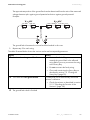
A
B
C
Green LED In operation
Red LED
Ground fault or varistor
defective
Yellow LED Disturbance
3. Read section 9 "Troubleshooting" (page 36) and,
if necessary, the user manual provided. The
meaning of the LED's as well as the error messages
and status messages on the display are described
in this section.
26
SB11_12_17-IEN094131
Installation Guide
SMA Solar Technology AG
Commissioning the Sunny Boy
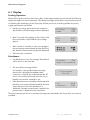
6.1 Display
Feeding Operation
After fault-free grid connection of the Sunny Boy, it takes approximately one minute until the following
display messages are shown alternately. The display messages shown before only have the purpose
of indicating the initialization of the Sunny Boy and the process of controlling whether the power
supply requirements are fulfilled.
• Initially, the energy generated on the respective
day and the current operating mode are displayed.
• After 5 seconds or by tapping on the enclosure lid,
the current feed-in output and the input voltage
appear.
E-today
Mode
Pac
Vpv
0Wh
MPP
903W
260V
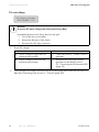
• After a further 5 seconds, or when you tap again,
the total energy produced and the time the Sunny
Boy has been connected to the grid are displayed.
• Then the cycle is restarted.
Disturbance
• If a disturbance occurs, the message "Disturbance"
will be shown in the status bar.
E-today
0Wh
Mode Disturbance
• The exact failure message follows.
For example, if the grid disturbance message
shown here is displayed immediately after
connection, it may be due to the fact that the AC
wire is not correctly connected or the line circuit
breaker has not been switched on yet.
• If the disturbance was caused by a measured value
that does not correspond to the standard, the value
measured at the time of the disturbance is
displayed. If another measurement is possible, the
present value is displayed in the second line.
Disturbance
Vac-Bfr
at:
present:
261W
245V
The precise meaning of the error and status messages are described in the Sunny Boy's user manual
provided.
Installation Guide
SB11_12_17-IEN094131
27
Commissioning the Sunny Boy
SMA Solar Technology AG
PV overvoltage
!PV-Overvoltage!
!DISCONNECT DC!
NOTICE!
Excessive DC input voltage can destroy the Sunny Boy!
Immediately disconnect the Sunny Boy from the grid!
1. Turn off the line circuit breaker.
2. Remove the Electronic Solar Switch.
3. Disconnect the DC plug connectors.
1. Check DC voltage!
Result
☑ The DC voltage is higher than the
maximum input voltage.
☑ The DC voltage is lower than the
maximum input voltage.
Action
• Contact the planner / installer of the PV
generator.
• Reconnect the Sunny Boy to the PV
generator as described in section
5.5 "Connecting the PV Generator (DC)"
(page 23).
2. If the message occurs again, disconnect the Sunny Boy again and contact the Serviceline of
SMA Solar Technology (see section 13 "Contact" (page 47)).
28
SB11_12_17-IEN094131
Installation Guide
SMA Solar Technology AG
Commissioning the Sunny Boy
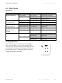
6.2 Blink Codes
Overview
Green
glows continuously
Red
is not glowing
glows continuously
Flashes quickly
(3 x per second)
Flashes slowly
(1 x per second)
Briefly goes out
(Approx. 1x per
second)
is not glowing
is not glowing
glows continuously
Yellow
is not glowing
is not glowing
glows continuously
is not glowing
is not glowing
Status
OK (feeding operation)
Disturbance
OK (initialization)
OK (stop)
Disturbance
is not glowing
glows continuously
is not glowing
is not glowing
OK (waiting, grid monitoring)
Disturbance
is not glowing
glows continuously
is not glowing
is not glowing
OK (derating)
Disturbance
is not glowing
is not glowing
glows/flashes
is not glowing
glows/flashes
OK (night shutdown)
Disturbance
Disturbance
Disturbance
glows continuously
Feeding Operation
After a fault-free grid connection of the Sunny Boy, it
takes approximately one minute until the green LED is
continuously on. The blink codes shown before only have
the purpose of indicating the initialization of the Sunny
Boy and the process of controlling whether the power
supply requirements are fulfilled.
Installation Guide
SB11_12_17-IEN094131
29
Commissioning the Sunny Boy
SMA Solar Technology AG
Disturbance or Fault
If the Sunny Boy detects a disturbance or fault, this event is indicated through a blink code of the
yellow and, where applicable, the red LEDs.
For example, if the yellow LED glows for 5 seconds immediately after connection, then goes out for
3 seconds and then flashes briefly twice, there is a grid fault. This can be due to the fact that either
the AC cable has not been connected correctly or the line circuit breaker has not yet been switched
on.
Explanation of the Blink Codes
For a detailed description of the blink codes, see the provided Sunny Boy user manual.
30
SB11_12_17-IEN094131
Installation Guide
SMA Solar Technology AG
Commissioning the Sunny Boy
PV overvoltage
(Yellow LED flashes 4 times quickly in succession)
NOTICE!
Excessive DC input voltage can destroy the Sunny Boy!
Immediately disconnect the Sunny Boy from the grid!
1. Turn off the line circuit breaker.
2. Remove the Electronic Solar Switch.
3. Disconnect the DC plug connectors.
1. Check DC voltage!
Result
☑ The DC voltage is higher than the
maximum input voltage.
☑ The DC voltage is lower than the
maximum input voltage.
Action
• Contact the planner / installer of the PV
generator.
• Reconnect the Sunny Boy to the PV
generator as described in section
5.5 "Connecting the PV Generator (DC)"
(page 23).
2. If the message occurs again, disconnect the Sunny Boy again and contact the Serviceline of
SMA Solar Technology (see section 13 "Contact" (page 47)).
Installation Guide
SB11_12_17-IEN094131
31
Opening and Closing
SMA Solar Technology AG
7 Opening and Closing
NOTICE!
Electrostatic discharges can damage the Sunny Boy!
Internal components of the Sunny Boy can be irreparably damaged by electrostatic
discharge.
• Ground yourself before touching a component.
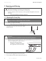
7.1 Opening the Sunny Boy
DANGER!
Danger to life due to high voltages in the Sunny Boy!
Before you open the Sunny Boy:
• Switch off the line circuit breaker and secure it to prevent it from being reactivated.
1. Pull the Electronic Solar Switch downwards, slightly
towards the wall.
DANGER!
Danger to life due to unsafe disconnection from the PV generator!
Safe disconnection from the PV generator is only guaranteed after removal of the Electronic
Solar Switch and of all DC plug connectors.
• Remove the DC plug connector
immediately to completely disconnect
the PV generator from the Sunny Boy.
2. Disconnect the PV generator from the Sunny Boy.
3. Check whether all LEDs and the display have gone out.
32
SB11_12_17-IEN094131
Installation Guide
SMA Solar Technology AG
Opening and Closing
DANGER!
Danger to life due to high voltages in the Sunny Boy!
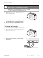
The capacitors in the Sunny Boy require 15 minutes to discharge.
• Wait 15 minutes before opening the Sunny Boy.
4. Remove all screws from the enclosure lid and pull
the lid forward smoothly.
5. Remove the PE connection from the lid by loosening
the locking device of the PE connection on the lid.
☑ The Sunny Boy is free of voltage and you can work
on it.
7.2 Closing the Sunny Boy
1. Connect the protective earth (PE) to the enclosure lid.
2. Secure the enclosure lid of the Sunny Boy by evenly
tightening the 4 lid screws.
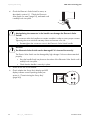
3. Check the DC plug connector for correct polarity
and connect it.
Installation Guide
SB11_12_17-IEN094131
33
Opening and Closing
SMA Solar Technology AG
4. Check the Electronic Solar Switch for wear, as
described in section 8.1 "Check the Electronic
Solar Switch for wear" (page 35), and attach until
it audibly locks into place.
NOTICE!
Manipulating the connector in the handle can damage the Electronic Solar
Switch!
The connector within the handle must remain movable in order to ensure proper contact.
Tightening the screw voids all warranty claims and creates a fire risk.
• Do not tighten the connector screw in the Electronic Solar Switch handle.
NOTICE!
The Electronic Solar Switch can be damaged if it is inserted incorrectly!
The Electric Solar Switch can be damaged by high voltages if it has not been attached
properly.
• Press the handle firmly into place on the socket of the Electronic Solar Switch until it
audibly locks into place.
• Check that the handle is securely in place.
5. Switch on the line circuit breaker.
6. Check whether the Sunny Boy's display and LED
display indicate normal operating mode (see
section 6 "Commissioning the Sunny Boy"
(page 26)).
34
SB11_12_17-IEN094131
Installation Guide
SMA Solar Technology AG
Maintenance and Cleaning
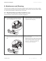
8 Maintenance and Cleaning
Check the correct operation of the Sunny Boy at regular intervals. Impurities such as dust or pollen
can cause heat accumulation that can lead to yield losses. Also check the Sunny Boy and the cables
for visible external damage. Undertake repairs if necessary.
8.1 Check the Electronic Solar Switch for wear
Check the Electronic Solar Switch for wear before plugging it in.
Result
☑ The metal tongues inside the connector
have no damage and no discoloration.
Action
1. Attach the Electronic Solar Switch handle.
2. Commission the Sunny Boy.
☑ The metal tongues inside the connector
The Electronic Solar Switch can no longer reliably
have a brown discoloration or are burned disconnect the DC side.
off.
1. Replace the Electronic Solar Switch handle
before attaching it again (order number see
section 12 "Accessories" (page 46).
2. Commission the Sunny Boy.
Installation Guide
SB11_12_17-IEN094131
35
Troubleshooting
SMA Solar Technology AG
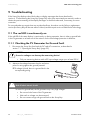
9 Troubleshooting
If the Sunny Boy displays other blink codes or display messages than those described in
section 6 "Commissioning the Sunny Boy" (page 26), refer to the associated user manual in order to
obtain the precise meaning of the display messages or the blink codes and, if necessary, the error
correction.
Do not undertake any repairs that are not described here, but rather use the 24-hour replacement
service (the Sunny Boy will be sent within 24 hours) and the repair service of SMA Solar Technology.
9.1 The red LED is continuously on
If the red LED of the status display is continuously on during operation, there is either a ground fault
in the PV generator or at least one of the varistors for the overvoltage protection is defective.
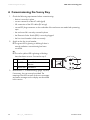
9.1.1 Checking the PV Generator for Ground Fault
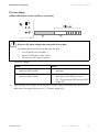
1. Disconnect the Sunny Boy from both the DC and AC connections, as described in
section 7.1 "Opening the Sunny Boy" (page 32).
NOTICE!
Excessive voltages can destroy the measuring device!
• Only use measuring devices with a DC input voltage range up to at least 500 V.
2. Measure the voltages between the plus and minus
pole of a string against the ground potential.
☑ If voltage is found, there is a ground fault in the
corresponding string.
DANGER!
Risk of lethal electric shock!
In case of a ground fault, the PV generator may carry high voltages.
• Do not touch the frame of the PV generator.
• Wait until no voltage can be measured.
• Do not connect strings with ground faults to the Sunny Boy.
36
SB11_12_17-IEN094131
Installation Guide
SMA Solar Technology AG
Troubleshooting
The approximate position of the ground fault can be determined from the ratio of the measured
voltages between plus against ground potential and minus against ground potential.
Example:
The ground fault is between the second and third module in this case.
3. Repeat step 2 for each string.
The table illustrated below shows the various results and corresponding measures.
Result
☑ You have found a ground fault.
Action
• The installer of the PV generator must
remedy the ground fault in the affected
string before you may reconnect the string
to the Sunny Boy.
• Do not reconnect the faulty string.
☑ You have found no ground fault.
• Close and commission the Sunny Boy as
described in section 7.2 "Closing the
Sunny Boy" (page 33).
It is likely that one of the thermally monitored
varistors is defective.
• Check the varistors as described in section
9.1.2 "Checking the Function of the
Varistors" (page 38).
☑ The ground fault check is finished.
Installation Guide
SB11_12_17-IEN094131
37
Troubleshooting
SMA Solar Technology AG
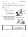
9.1.2 Checking the Function of the Varistors
Varistors are wearing parts. Their functioning becomes restricted through aging or due to repeated
responses as a result of overvoltages. It is therefore possible that one of the thermally monitored
varistors has lost its protective function, and thus the red LED is lit.
Position of varistors
You can determine the position of the varistors with the help of the illustration below.
Observe the following allocation of the
terminals:
• Terminal A: outer terminal (varistor
connection with loop [crimp])
• Terminal B: middle terminal
• Terminal C: outer terminal (varistor
connection without loop [crimp])
Check the function of the varistors as described below:
1. Open the Sunny Boy as described in section 7.1 "Opening the Sunny Boy" (page 32).
2. With the aid of a multimeter, determine for both
varistors in the installed state whether a conductive
connection exists between connectors B and C.
Result
Action
☑ There is a conducting connection. There is probably another fault in the Sunny Boy.
• Close the Sunny Boy as described in section
7.2 "Closing the Sunny Boy" (page 33).
• Contact the SMA Serviceline (see section
13 "Contact" (page 47)).
38
SB11_12_17-IEN094131
Installation Guide
SMA Solar Technology AG
Result
☑ There is no conducting
connection.
Troubleshooting
Action
The respective varistor is not working and must be
replaced.
Varistor failure is generally due to influences which affect
all varistors similarly (temperature, age, induced
overvoltage). SMA Solar Technology recommends that
you replace both varistors.
The varistors are specially manufactured for use in the
Sunny Boy and are not commercially available. They must
be ordered directly from SMA Solar Technology (see
section 12 "Accessories" (page 46)).
• To replace the varistors, proceed to step 3.
NOTICE!
The Sunny Boy could be irreparably damaged by overvoltage!
If varistors are missing, the Sunny Boy is no longer protected against overvoltages.
• Replacement varistors should be obtained as soon as possible.
• Do not operate the Sunny Boy without varistors in systems with a high risk of
overvoltages.
3. Insert an insertion tool into the openings of the
terminal contacts (1).
☑ The terminals will loosen.
If you do not receive an insertion tool for operating
the terminal clamps with your replacement
varistors, contact SMA Solar Technology. The
terminal contacts can also be provisionally serviced
by a screwdriver with a 3.5 mm blade width.
4. Remove the varistor (2).
5. Insert new varistor.
The pole with the small loop (crimp) must be fitted
to terminal A (3) when remounting.
6. Close the Sunny Boy as described in section
7.2 "Closing the Sunny Boy" (page 33).
☑ The check of the varistors is completed.
Installation Guide
SB11_12_17-IEN094131
39
Decommissioning
SMA Solar Technology AG
10 Decommissioning
10.1 Removing the Sunny Boy
CAUTION!
Risk of injury due to the heavy weight of the Sunny Boy!
• Take the weight of the Sunny Boy of approx. 25 kg into account.
1. Open the Sunny Boy as described in section 7.1 "Opening the Sunny Boy" (page 32).
2. Remove all cables from the Sunny Boy.
3. Close the Sunny Boy: fasten the enclosure lid to the Sunny Boy with the 4 screws.
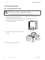
4. Loosen the lower screw between the Sunny Boy
und wall mounting bracket.
5. Remove the Sunny Boy from the wall mounting
bracket.
☑ The Sunny Boy has been removed.
40
SB11_12_17-IEN094131
Installation Guide
SMA Solar Technology AG
Decommissioning
10.2 Packaging the Sunny Boy
If possible, always package the Sunny Boy in the original packaging. If this is no longer available,
you can also use an equivalent box. The box must be completely closeable and made to support both
the weight and size of the Sunny Boy.
10.3 Storing the Sunny Boy
Store the Sunny Boy in a dry place where ambient temperatures are always between -25 °C and
+60 °C.
10.4 Disposing of the Sunny Boy
Dispose of the Sunny Boy at the end of its service life in accordance with the disposal regulations for
electronic waste which apply at the installation site at that time. Alternatively, send it back to SMA
Solar Technology with shipping paid by sender, and labeled "ZUR ENTSORGUNG" ("for disposal")
(see section 13 "Contact" (page 47).
Installation Guide
SB11_12_17-IEN094131
41
Technical Data
SMA Solar Technology AG
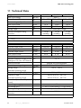
11 Technical Data
PV generator connection data
Max. input voltage
Input voltage, MPP range
PV start voltage, adjustable
Max. input current
Max. input power
Voltage ripple
Internal consumption during
operation
a)
SB 1100
UDC Max
UPV
UPV Start
IPV Max
PDC
UPP
SB 1200
SB 1700
a)
400 V
139 V ... 320 V 100 V ... 320 V 139 V ... 320 V
180 V
120 V
180 V
10 A
12.6 A
12.6 A
1210 W
1320 W
1850 W
< 10 % of the input voltage
<4W
<4W
<5W
(standby)
(standby)
(standby)
The maximum open circuit voltage, which can occur at a cell temperature of 10 °C, may not exceed the maximum input
voltage.
Grid connection data
Nominal output power
Peak output power
Nominal output current
Max. output current
Max. fuse protection
Harmonic distortion of output current
(at KUgrid < 2 %, PAC > 0.5 PACnom)
Short Circuit Proof
Nominal operating voltage
Voltage range
UAC nom
UAC
grid-side via current regulation
220 V / 230 V / 240 V
180 V ... 260 V
(extended operating range)
Nominal operating frequency
Frequency range
fAC nom
fAC
50 Hz / 60 Hz
50 Hz: 45.5 Hz ... 54.5 Hz
cos ϕ
60 Hz: 55.5 Hz ... 64.5 Hz
1
(extended operating range)
Power factor (at nominal output
power)
Overvoltage category
Test voltage (DC)
Test surge voltage
Internal consumption in night
operation
42
SB11_12_17-IEN094131
PAC nom
PAC max
IAC nom
IAC max
KIAC
SB 1100
1000 W
1100 W
4.4 A
5.6 A
SB 1200
1200 W
1200 W
5.2 A
6.1 A
16 A
<3 %
SB 1700
1550 W
1700 W
6.7 A
8.6 A
III
1.7 kV (1 s routine testing / 5 s type testing)
4 kV (serial interface: 6 kV)
0.1 W
Installation Guide
SMA Solar Technology AG
General data
EC Declaration of Conformity
Technical Data
SB1100
SB 1200
SB1700
You can download the EC Declaration of Conformity
in the download area at www.SMA.de/en under
Certificates.
440 mm x 339 mm x 214 mm (approx.)
approx. 22 kg approx. 23 kg approx. 25 kg
IP65
Dimensions (W x H x D)
Weight
Protection rating according to DIN EN
60529
Climatic conditions according to DIN EN 50178:1998 - 04
Location of type C:
Class 4K4H
Extended temperature range: -25 °C ... +60 °C
Extended humidity range: 0 ... 100 %
Transport of type E:
Operating temperature range
Max. operating altitude
Topology
Protection class
Noise emission (typical)
Protective function DC side
All-pole disconnection unit on the DC input
side
Overvoltage protection
Personal protection
Pole Confusion Protection
Protective function AC side
Short Circuit Proof
All-pole disconnection unit grid side
Extended air pressure range: 79.5 kPa ... 106 kPa
Class 2K3
Temperature range -25 °C ... +70 °C
-25 °C ...+60 °C
2000 m above mean sea level
Low frequency transformer
I
≤ 39 dB(A)
≤ 41 dB(A)
≤ 46 dB(A)
Electronic Solar Switch, DC plug connector
Thermally monitored varistors
Insulation monitoring (Riso > 1MOhm)
Via short-circuit diode
Current control
Automatic disconnection device
(SMA Grid Guard 2.1),
double implementation
Installation Guide
SB11_12_17-IEN094131
43
Technical Data
SMA Solar Technology AG
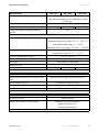
Communication interfaces
RS485 (galvanically isolated)
Radio
SB 1100
Electronic Solar Switch (ESS)
Electrical lifetime (in the event of a short
circuit, with a nominal current of 30 A)
Maximum switching current
Maximum switching voltage
Maximum PV power
Protection rating when plugged
Protection rating when unplugged
Efficiency
Max. efficiency
European efficiency
η max.
η euro
SB 1200
optional
optional
SB 1700
Min. 50 switching processes
30 A
800 V
approx. 10 kW
IP65
IP21
SB1100
93 %
91.6 %
SB 1200
92.1 %
90.7 %
SB1700
93.5 %
91.8 %
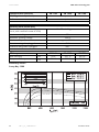
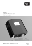
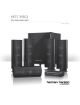
Efficiency curves
Sunny Boy 1200
44
SB11_12_17-IEN094131
Installation Guide
SMA Solar Technology AG
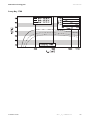
Technical Data
Sunny Boy 1700
Installation Guide
SB11_12_17-IEN094131
45
Accessories
SMA Solar Technology AG
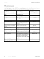
12 Accessories
In the following overview you will find the corresponding accessories and replacement parts for your
product. If needed, you can order these from SMA Solar Technology or your dealer.
Designation
Brief description
DC connection set Multi-Contact
3 mm
DC connection set Multi-Contact
4 mm
Tyco DC connection set
Multi-contact 3 adapter set max.
flow current: 21 A
Multi-contact 4 adapter set max.
flow current: 30 A
TYCO adapter set, max. flow
current: 30 A
ESS handle replacement part
Set of thermally monitored varistors
(2 pcs.) including insertion tool
SB-TVWZ
Insertion tool for varistor sets
Electronic Solar Switch
Replacement varistors
Insertion tool for replacing the
varistors
Positive grounding set
Negative grounding set
RS485 upgrade kit
Radio upgrade kit
Bluetooth® Wireless
Technology upgrade kit
46
SB11_12_17-IEN094131
Upgrade kit for the positive
connection to ground of the DC input
Upgrade kit for the negative
connection to ground of the DC input
RS485 interface
Radio Piggy-Back for upgrading a
Sunny Boy for communication with
Sunny Beam, including antenna,
coaxial cable, and PG cable gland
(metal)
Bluetooth interface
SB 1100 / 1200 / 1700
SMA order number
SWR-MC
MC-SET
TYCO-SET
ESS-HANDLE:01
SB-TV3
SB-TVWZ
ESHV-P-NR
ESHV-N-NR
485PB-NR
BEAMPB-NR
On request
Installation Guide
SMA Solar Technology AG
Contact
13 Contact
If you have technical problems concerning our products, contact the SMA Serviceline. We require the
following information in order to provide you with the necessary assistance:
• Inverter type
• Type and number of modules connected
• Communication type
• Serial number of the Sunny Boy
• Blink code or display of the Sunny Boy
SMA Solar Technology AG
Sonnenallee 1
34266 Niestetal, Germany
www.SMA.de
Serviceline
Inverters:
+49 561 9522 1499
Communication:
+49 561 9522 2499
Fax:
+49 561 9522 4699
E-mail:
[email protected]
Installation Guide
SB11_12_17-IEN094131
47
Contact
48
SMA Solar Technology AG
SB11_12_17-IEN094131
Installation Guide
SMA Solar Technology AG
Installation Guide
Contact
SB11_12_17-IEN094131
49
Contact
50
SMA Solar Technology AG
SB11_12_17-IEN094131
Installation Guide
SMA Solar Technology AG
Legal Restrictions
The information contained in this document is the property of SMA Solar Technology AG. Publishing its content, either partially or
in full, requires the written permission of SMA Solar Technology AG. Any internal company copying of the document for the
purposes of evaluating the product or its correct implementation is allowed and does not require permission.
Exclusion of liability
The general terms and conditions of delivery of SMA Solar Technology AG shall apply.
The content of these documents is continually checked and amended, where necessary. However, discrepancies cannot be
excluded. No guarantee is made for the completeness of these documents. The latest version is available online at www.SMA.de
or from the usual sales channels.
Guarantee or liability claims for damages of any kind are excluded if they are caused by one or more of the following:
• Damages during transportation
• Improper or inappropriate use of the product
• Operating the product in an unintended environment
• Operating the product whilst ignoring relevant, statutory safety regulations in the deployment location
• Ignoring safety warnings and instructions contained in all documents relevant to the product
• Operating the product under incorrect safety or protection conditions
• Altering the product or supplied software without authority
• The product malfunctions due to operating attached or neighboring devices beyond statutory limit values
• In case of unforeseen calamity or force majeure
The use of supplied software produced by SMA Solar Technology AG is subject to the following conditions:
• SMA Solar Technology AG rejects any liability for direct or indirect damages arising from the use of software developed by
SMA Solar Technology AG. This also applies to the provision or non-provision of support activities.
• Supplied software not developed by SMA Solar Technology AG is subject to the respective licensing and liability agreements
of the manufacturer.
SMA Factory Warranty
The current guarantee conditions come enclosed with your device. These are also available online at www.SMA.de and can be
downloaded or are available on paper from the usual sales channels if required.
Trademarks
All trademarks are recognized even if these are not marked separately. Missing designations do not mean that a product or brand
is not a registered trademark.
The Bluetooth® word mark and logos are registered trademarks owned by Bluetooth SIG, Inc. and any use of such marks by SMA
Solar Technology is under license.
SMA Solar Technology AG
Sonnenallee 1
34266 Niestetal
Germany
Tel. +49 561 9522-0
Fax +49 561 9522-100
www.SMA.de
E-Mail: [email protected]
© 2004 to 2009 SMA Solar Technology AG. All rights reserved
Installation Guide
SB11_12_17-IEN094131
51
SMA Solar Technology AG
www.SMA.de