1
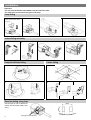
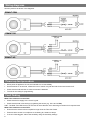
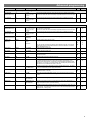
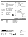
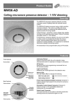
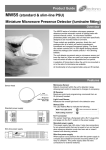
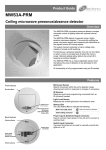
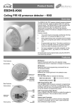
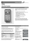
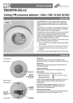
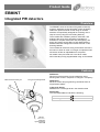
Product Guide EBMINT Integrated PIR detectors Overview The EBMINT series of miniature PIR (passive infrared) presence detectors provide automatic control of lighting loads with optional manual control using an infrared handset. It is specifically designed for mounting onto a lamp or louvre (using the louvre fitting bracket). Three models are available: premium, direct dim, and analogue dim all of which will switch incandescent, fluorescent, compact fluorescent and LED lighting. The direct dim variant controls DALI or DSI digital dimming ballasts whilst the analogue dim variant controls 1-10V dimming ballasts. The unit detects movement using a PIR sensor and turns the load on. When an area is no longer occupied the load will switch off after an adjustable time out period. All models come pre-wired with a 1m silicon cable. All functionality is fully programmable using an IR handset. Features PIR Sensor Detects movement within the unit’s detection range, allowing load control in response to changes in occupancy. Cable to luminaire control gear Fixing for louvre fitting bracket IR Receiver Receives control and programming commands from an IR (infrared) handset. Light Level Sensor Measures the overall light level in the detection area Status LED The LED flashes Red to indicate the following: Walk Test LED active Valid setting received PIR lens which covers... IR Receiver Light Level Sensor Status LED when movement is detected Detection diagram Range Note: illustration shows an average of the walk across and walk towards figures below. Walk across 2 Walk towards Height Range Diameter Height Range Diameter 7m 16m 7m 10m 2.8m 9m 2.8m 5m Installation The product is designed to be mounted directly to the outside of a luminaire. The detector should be sited so that the occupants of the room fall inside the detection pattern (shown opposite), at a recommended ceiling height of 2.8m. Note that the lower the sensor is installed the smaller the detection range will be, subject to the parameters shown on the detection diagram. For optimum operation of the lux sensor, the lens must shielded as much as possible from the light source. Avoid direct sunlight entering the sensor. Do not site within 1m of forced air heating or ventilation. Do not fix to a vibrating surface. Sensor functionality Detection mode Presence When movement is detected the load will automatically turn on. When the area is no longer occupied the load will automatically switch off after an adjustable time period. Sensitivity to movement of the PIR sensor can be adjusted using the Sensitivity parameter. HINT: To assist in setting the Sensitivity, turn on the Walk Test LED which will flash red when movement is detected. Switch Level On/Off Occupancy detection can be made dependant on the ambient light level using the Lux On Level and Lux Off Level parameters. Maintained Illuminance (daylight harvesting) - DD and AD variants only The detector measures the overall light level in the detection area and calculates the correct output for the luminaires, to achieve a preset lux level (maintained illuminance or daylight harvesting). Burn-in - DD and AD variants only Burn-in - DD and AD variants only Overview It is a requirement of many fluorescent lamp manufacturers to have the lamps on at maximum output for a period of time to guarantee lamp life (refer to the manufacturer’s datasheet for details). As the EBMINT-DD & AD are able to dim the lamps using DALI/DSI or 1-10V, the products provide a facility to disable this for a given period of time. Operation By setting the “Burn in” parameter, you can select a time during which the lamps are not allowed to deviate from maximum output. The unit counts the time, and even remembers how long has elapsed in the event of a power failure. To cancel the burn in function, simply select a time of 0. Note that when the lamps are changed, the burn in time should be set again. 3 Installation Important The unit must be fitted at least 50mm from the end of the tube. The cable must not touch the any part of the lamp. Lamp fitting 1 2 3 4 Select correct clip for lamp; T5 or T8. Louvre fixing assembly 1 2 3 4 Compact reflector fitting Louvre fitting 1 1 2 2 3 4 Panel mounting using lugs Use the lugs on rear of detector to secure into thin sheet metal (1mm max.). Fixing lugs for gear tray fixing 4 Gear tray fixing dimensions Batten installation 1 2 Remove gear tray cover Isolate supply to light fitting Remove lamp 3 4 Remove Ø20mm knockout or make a Ø20mm hole in gear tray or luminaire body. 5 Insert supplied Ø20mm grommet into hole. 6 PRM version shown ly pp su l a ly ut r pp Ne su h t ly r pp Ea su e Liv Feed cable through end-cap knockout or between gear tray and housing of luminaire. r cto ete ble ca D 7 Live feed to ballast Supplied terminal block Clip detector to tube. Connect the Neutral. Disconnect the Live to the ballast. Using the supplied terminal block, connect the Live switched output (Black) from detector to the Live feed of the ballast. Ensure that the detector wired-up according to wiring diagrams on page 6. 5 Wiring diagrams Wire the products as shown in the diagrams. EBMINT-PRM EBMINT-DD EBMINT-AD Power-up test procedure When power is applied to the unit, the load will turn on immediately. Set the timeout to 10 seconds, vacate the room or remain very still and wait for the load to switch off . Check that the load switches on when movement is detected. The unit is now ready for programming. Fault finding What if the load does not turn ON? Check that the live supply to the circuit is good. Check that the load is functioning by bypassing the sensor (e.g. link L and L/ Out). HINT: The Walk Test LED function can be used to check that the unit is detecting movement in the required area. What if the load does not turn OFF? Ensure that the area is left unoccupied for longer than the Time Out Period. Ensure that the sensor is not adjacent to circulating air, heaters or lamps. 6 If the unit “false triggers” reduce the sensitivity using the sensitivity settings Basic programming - PRM, DD and AD variants The functionality of the EBMINT-PRM, DD & AD are controlled by a number of parameters which can be changed or programmed by any of the following devices: UHS5 Infrared Handset. See below for programmable functions. UNLCDHS Infrared Handset (with LCD). See user guide for full programming details. For most basic programming operations the UHS5 handset can be used and the following procedures are based on using this device. Point the handset at the Sensor and send the required programming commands to the unit as shown below. Valid commands will be indicated by a red LED flash. See page 1 for details of other LED responses. Note: other functions on the UHS5 which are not shown below are not applicable to this product. Number of Shift key presses Parameter Name Default Value 0 SHIFT 1 1 SHIFT 2 SHIFT 1 2 SHIFT 2 SHIFT 1 3 SHIFT 2 SHIFT 1 UHS5 Handset Graphics Description SHIFT 2 Button Activation On / Raise On Raise Turn lights on or to raise lights. Off / Lower Off Lower Turn lights off or to lower lights. On Off When set to On this causes a red LED to flash on the sensor when it detects movement. Use this feature to check for adequate sensitivity levels. Time Out 20 mins (Time adjustment) 1, 10 & 20 minutes 5, 15 & 30 minutes Lux on level (Switch level on) 9 2, 5 & 7 4, 6 & 9 Light Level (DD & AD only) 6 (600) Lux off level (Switch level off) 9 Load Type (DD only) DALI Sensitivity 9 Walk test Off 2, 5 & 7 Shift 0 0 4 (400) 6 (600) 9 (900) 4, 6 & 9 3, 6 & 8 50 Sets a target light level to be maintained by the lighting system. Lux level setting to switch the luminaires off during occupancy if the ambient light level goes above the setting (adjustable between 1 and 9). Level 9 will always keep the lights on. This setting can be used for “window row switching”. Note: the Lux Off Level value must always be greater than the Lux On Level value. 2-DALI 7-DSI 1, 5 & 9 Once the detector is turned on, this value sets how long the lights will stay on once movement has ceased. Lux level setting to prevent the luminaires being switched on if the ambient light level is sufficient (adjustable between 1 and 9). The luminaires will always be switched on at level 9. 2 (200) 5 (500) 7 (700) Defaults Burn-in (DD & AD only) 10 seconds 2-DALI on Sets the ballast control protocol to be used by the output channel. Sensitivity level for detecting movement. 1 = low sensitivity 9 = high sensitivity D Returns the unit to the default settings. 100 Determines how long the output will be at 100% so that lamps ‘burn-in’. The ’burn-in’ time is not affected by power supply interruptions. Use this button to select the settings in red and blue signified by the ‘Shift 1’ and ‘Shift 2’ LEDs 7 Advanced programming Parameter Name Default Value UHS5 UNLCDHS When set to On this causes a red LED to flash on the sensor when it detects movement. Use this feature to check for adequate sensitivity levels. Once the detector is turned on, this value sets how long the lights will stay on once movement has ceased. Select 0 for 10 second delay – use for commissioning only. When a manual operation occurs, either via the switch input or the infrared, it invokes the timeout period. Example 1: a detector in presence mode has a detector timeout of 15 minutes and a manual timeout of 3 minutes. When the user leaves the room they press the off button. The sensor will revert to automatic after 3 minutes, and then walking back in the room will turn the lights on. Example 2: using the settings above, the user turns the lights off (say for a presentation) but stays in the room. Every time a movement is detected, the manual timeout period is re-triggered, but when it doesn’t pick up for the short timeout period, the sensor will timeout and revert to automatic. This means the lights may turn on inadvertently during the presentation, if the occupants are still for the manual timeout period, so adjust the timing carefully. Sensitivity level for detecting movement when the detector is already on. *UHS5 sets Sensitivity On and Off to the same value. * * Range / Options Description Detector Parameters Walk Test LED Off On or Off Time Out (Time adjustment) Manual Time Out 20 minutes 0-99 minutes 10 minutes 0-99 minutes Sensitivity On 9 1 (min) to 9 (max) Sensitivity Off 9 1 (min) to 9 (max) Sensitivity level for detecting movement when the detector is off. *UHS5 sets Sensitivity On and Off to the same value. Lux time 0 0 (disabled) 1-99 minutes Power Up State On On or Off If the detector measures the lux level and decides that the output needs switching on or off as a consequence, the lux time must elapse first. If at any time during the timed delay the lux change reverses then the process is cancelled. Select No for a 30 second delay on start up. If Yes is selected, there will be no delay on start up and the detector will always power up detecting. Disable Detector N Y or N Disables detection, leaving the relay output permanently off with the dimming output operational. This mode is used when the unit is for maintained illuminance only. On Delay 0 minutes 0-99 minutes Inhibit 4 seconds 1 to 999 seconds The On Delay to allows the first channel to switch on after the second channel. A typical application for this would be where a detector is controlling lighting and air conditioning in an area. When the occupant is detected, the lighting will be turned on immediately, whereas the air conditioning may be turned on after 15 minutes. If the area is vacated and the detector times out before the delay, then the air conditioning would never go on. The delay can be set only for channel 1 using the on delay parameter. When the detector turns off, a delay is instigated to prevent retriggering. In certain circumstances this delay may not be enough. This parameter allows the delay to be changed. - - Restores factory default settings Raise (DD & AD only) - - Increase light level. Reverts when occupancy cycle complete. Lower (DD & AD only) - - Decrease light level. Reverts when occupancy cycle complete. Scene up - - Steps up between 6 pre-defined scenes. Scene down - - Steps down between 6 pre-defined scenes. Scene # - - Select the individual scene, between 0 and 6. (1 = min. output; 2 = 10%; 3 = 25%; 4 = 50%; 5 = 75%; 6 = 100%) Override On - - If the lights are off, sending the IR command will turn them on immediately and revert to automatic operation using the manual timeout period. Override Off - - If the lights are on, sending the IR command will turn them off immediately. After the manual timeout period (described above), the sensor will revert to automatic. Cancel - - Cancels the on or off override, returning the detector to normal operation. Factory default User Modes Readback function (only with UNLCDHS handset ) The UNLCDHS has the ability to read back the settings stored in a device. To read back individual parameters Navigate to the parameter and press the ‘R’ (Read) button whilst pointing at the device. The handset will click when the parameter has been read back, the device will flash its LED, and the value will be shown against the parameter in the menu. To read back all of the parameters in a menu Press and hold the ‘R’ (Read) button for more than 1 second. The handset will click every time a parameter is received The device will show multiple flashes of its LED All of the values will be shown against the parameters in the menu. The individual parameters may be edited and then saved as a ‘Macro’. Notes If a parameter(s) has been missed because of a communication error, the missing value(s) is replaced by dashes. When reading back, the Channel 1 relay (where fitted) will temporarily be switched off, and will return to it’s normal state 2 seconds after the read back has been completed. 8 Advanced programming Parameter Name Default Value Range / Options Description UHS5 UNLCDHS Channel 1 –Switching Channel( PRM & AD only) Lux on level (Switch level on) 9 Lux off level (Switch level off) 9 1 to 9 For a higher resolution a scale of 101-199 is available 1 to 9 For a higher resolution a scale of 101-199 is available Sets a minimum light level below which the PIR sensor is enabled, allowing lights to be turned on by movement. Note: the Lux Level Off value must always be greater than the Lux Level On value. Sets a maximum light level above which the PIR sensor is disabled, preventing lights from being turned on by movement. Sets a minimum light level below which the PIR sensor is enabled, allowing lights to be turned on by movement. Note: the Lux Level Off value must always be greater than the Lux Level On value. Sets a maximum light level above which the PIR sensor is disabled, preventing lights from being turned on by movement. Channel 2 -Dimming Channel (DD & AD only) Lux on level (Switch level on) 9 Lux off level (Switch level off) 9 Light Level 600 1 to 998 (999 disabled) Sets a target light level to be maintained by the lighting system. DALI DSI DALI Sets the ballast control protocol to DSI. Sets the ballast control protocol to DALI. For a higher resolution a scale of 101-199 is available 1 to 9 For a higher resolution a scale of 101-199 is available (maintained illuminance) Load Type (DD only) 1 to 9 DALI On Max Value 100% 0 to 100% DALI On provides a permanent voltage to DALI ballasts when DALI has not been implemented correctly in the ballast. Maximum number of ballasts is 4 unless the relay is disabled then it is 10. Maximum dimming output level. Min Value 0% 0 to 100% Minimum dimming output level. Memorise N Yes or No If this is set to Yes, the last manual lux level set will be memorised and used as the new switch on level. 0 to 99 Dimming output level when switched on (0-99). On value 99 Off value 0 0 to 99 Dimming output level when switched off (0-99). If a non-zero off value is set, then the output will toggle between this value and completely off depending on the switch level on and off values. For example, if it is light outside, the fittings will be off if there is no occupancy. If it is dark outside, they will adopt the preset off value. This feature is only enabled if ‘Min value’ is set to 99. Burn-in 0 0 (disabled) or 1 to 999 hours Determines how long the output will be at 100% so that lamps ‘burn-in’. The ’burnin’ time is not affected by power supply interruptions. Fade value 10 0 to 99 After occupancy ceases, this dimming output level is loaded for the fade time (adjustable between 0 and 99). Fade mins 0 0 to 99 This is the time period (adjustable between 0 and 99 minutes) that the luminaire will be held at the fade value before turning off. A value of 0 disables the fade function. Speed On 40 Measured in 0.1 sec intervals. Determines the dimming response speed after the setup time has finished. Speed Set 5 Measured in 0.1 sec intervals. Determines the dimming response speed during the set up time. Measured in 0.1 sec intervals. If set to 0 will disable dimming for “Set seconds” below, used if fittings are required to warm up before dimming. Set Seconds 120 1 to 999 seconds Determines how long the dimming response set-up period lasts on power-up or on setting change. This enables the desired lux level to be achieved rapidly when the lights come on, or during setup. 9 Technical data Dimensions Weight Supply Voltage Frequency Circuit protection Dimming output Maximum Switching Load Number of ballasts Power consumption Cable specification Temperature Humidity Material IP rating Compliance See diagrams opposite. 0.10kg 120VAC +/- 10%, 230VAC +/- 10% 50/60Hz 10A Basic insulation only. Although low voltage, this is not an SELV output and should be treated as if mains potential. Use mains rated wiring. 2 Amps fluorescent and incandescent lighting. 2 Amps compact fluorescent lighting. 2 Amps low energy lighting. 2 Amps low voltage lighting (switch primary of transformer). Switch SON lighting loads via a contactor. Up to 4 dimming ballasts. PRM On 307mW, Off 228mW DD On 357mW, Off 228mW AD On 344mW, Off 268mW 1m, silicon insulation and sheath. PRM 3 x 0.75mm2 AD & DD 3 x 0.75mm2 & 2 x 0.50mm2 -10ºC to 50ºC 5 to 95% non-condensing Flame retardant ABS/PC Type Class 2 IP40 EMC-2004/108/EC LVD-2006/95/EC UK patent GB2498572 and international patents applied for. Part numbers Detectors Accessories Part number EBMINT-AD EBMINT-DD EBMINT-PRM UHS5 UNLCDHS Description Integrated PIR detector AD 1-10V Integrated PIR detector DD DALI/DSI Integrated PIR detector PRM Programming IR handset Universal LCD IR handset IMPORTANT NOTICE! This device should be installed by a qualified electrician in accordance with the latest edition of the IEE Wiring Regulations and any applicable Building Regulations. Due to our policy of continual product improvement CP Electronics reserves the right to alter the specification of this product without prior notice. 10 C.P. Electronics Ltd Brent Crescent London NW10 7XR United Kingdom Tel: + 44 (0) 333 900 0671 Fax: + 44 (0) 333 900 0674 www.cpelectronics.co.uk [email protected] Ref: #WD676 Issue 2