1
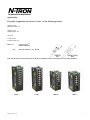
308FX2, 309FX, 316TX, 317FX Industrial Ethernet Switches User Manual & Installation Guide (Revised 2010-7-30) 1 Table of Contents Applicability: ..................................................................................................................................................... 3 Safety Warnings ................................................................................................................................................. 4 Overview: 308FX2/309FX/316TX/317FX Industrial Ethernet Switches.......................................................... 8 Key Features....................................................................................................................................................... 9 Installation .......................................................................................................................................................... 9 Panel and Rack Mounting ................................................................................................................................ 10 Front Panel ....................................................................................................................................................... 11 Applying Power (Side View) ........................................................................................................................... 12 N-Tron Switch Grounding Techniques ............................................................................................................ 13 RJ45 Connector Crimp Specifications ............................................................................................................. 14 Connecting the Unit ......................................................................................................................................... 14 Serial Interface ................................................................................................................................................. 15 Troubleshooting ............................................................................................................................................... 15 Command Line Interpreter ............................................................................................................................... 17 Logging In (password protection) .................................................................................................................... 18 CLI Tree of Menus ........................................................................................................................................... 19 CLI Menus and Commands ............................................................................................................................. 20 Home Menu .................................................................................................................................................. 20 Top Level Info.......................................................................................................................................... 20 System Menu ................................................................................................................................................ 21 N-ViewTM Menu....................................................................................................................................... 21 System Info .............................................................................................................................................. 22 Restoring defaults..................................................................................................................................... 22 Switch Menu ................................................................................................................................................ 22 Filters ....................................................................................................................................................... 22 Ports ......................................................................................................................................................... 23 Key Specifications (308FX2/FXE2) ................................................................................................................ 26 Key Specifications (309FX/FXE) .................................................................................................................... 28 Key Specifications (316TX) ............................................................................................................................ 30 Key Specifications (317FX/FXE) .................................................................................................................... 32 (Revised 2010-7-30) 2 Applicability: This guide is applicable to Firmware Version 1 of the following products: 308FX2-N-XX 308FXE2-N-XX-YY 309FX-N-XX 309FXE-N-XX-YY 316TX-N 317FX-N-XX 317FXE-N-XX-YY = N for N-ViewTM = Blank Otherwise Where: N XX = ST or SC and YY = -15, -40, -80 Note: The firmware version can be seen on the power up banner on the serial console for any of these products. 316TX (Revised 2010-7-30) 317FX 308FX2 309FX 3 Copyright, © N-TRON Corp., 2010 820 S. University Blvd., Suite 4E Mobile, AL USA 36609 All rights reserved. Reproduction, adaptation, or translation without prior written permission from NTRON Corp. is prohibited, except as allowed under copyright laws. Ethernet is a registered trademark of Xerox Corporation. All other product names, company names, logos or other designations mentioned herein are trademarks of their respective owners. The information contained in this document is subject to change without notice. N-TRON Corp. makes no warranty of any kind with regard to this material, including, but not limited to, the implied warranties of merchantability or fitness for a particular purpose. In no event shall N-TRON Corp. be liable for any incidental, special, indirect or consequential damages whatsoever included but not limited to lost profits arising out of errors or omissions in this manual or the information contained herein. Warning: Do not perform any services on the unit unless qualified to do so. Do not substitute unauthorized parts or make unauthorized modifications to the unit. Do not operate the unit with the top cover removed, as this could create a shock or fire hazard. Do not block the air vents on the sides or the top of the unit. Do not operate the equipment in the presence of flammable gasses or fumes. Operating electrical equipment in such an environment constitutes a definite safety hazard. Do not operate the equipment in a manner not specified by this manual. Safety Warnings GENERAL SAFETY WARNING: If the equipment is used in the manner not specified by N-TRON Corp., the protection provided by the equipment may be impaired. Contact Information N-TRON Corp. 820 South University Blvd. Suite 4E Mobile, AL 36609 TEL: (251) 342-2164 FAX: (251) 342-6353 Website: www.n-tron.com Email: [email protected] (Revised 2010-7-30) 4 ENVIRONMENTAL SAFETY WARNING: Disconnect the power and allow to cool 5 minutes before touching. ELECTRICAL SAFETY WARNING: Disconnect the power cable before removing the enclosure top. WARNING: Do not operate the unit with the top cover removed. WARNING: Properly ground the unit before connecting anything else to the unit. Units not properly grounded may result in a safety risk and could be hazardous and may void the warranty. See the grounding technique section of this user manual for proper ways to ground the unit. WARNING: Do not work on equipment or cables during periods of lightning activity. WARNING: Do not perform any services on the unit unless qualified to do so. WARNING: Do not block the air vents. WARNING: Observe proper DC Voltage polarity when installing power input cables. Reversing voltage polarity can cause permanent damage to the unit and void the warranty. LASER SAFETY (FXE-40,-80 Only) CAUTION: CLASS 1 LASER PRODUCT. Do not stare into the laser! UL/cUL Hazardous Location Installation Requirements 1. WARNING: Explosion hazard, do not disconnect while circuit is live, unless area is known to be non-hazardous. 2. WARNING: Install only in accordance with Local & National Codes of Authorities Having Jurisdiction. 3. Power must be supplied by an isolating source, and a 3.3A max rated UL recognized fuse must be installed immediately before the unit. 4. Class I, Div 2 installations require that all devices connected to this product must be UL listed for the area in which it is installed. 5. Only UL listed wiring with temperature ratings greater than 90OC permitted for Class I, Div 2 installations operating at temperatures up to 70OC ambient. 6. Limited Operating Voltage: 12-30V for Class I, Div 2 installations. (Revised 2010-7-30) 5 (Revised 2010-7-30) 6 ATEX Installation Requirements 1. The conductor size of the phase conductor must be in the range of 0.05-2.08 mm2. 2. Field wiring must be suitable for a minimum of 110°C. 3. Ethernet Switches are intended for mounting in an IP54 enclosure in a pollution degree 2 environ ment. 4. Temperature testing of the Ethernet Switches was conducted on the switch itself in an 85°C aircirculating oven and resulted in a Temperature Code of T4. However, end-product temperature testing shall be considered. 5. The end user shall provide bonding means as necessary. All bonding equipment (components) shall be evaluated according to EN 60079-15:2005 and covered by a component certificate for the actual use. When installing bonding components that will pass through an enclosure wall, they must have a minimum of IP54 rating equal to the enclosure. All electrical clearances must be maintained per the manufacturer‟s instructions of the bonding component or per EN 60079-15:2005. 6. Ethernet Switch requires protection against transients. The end-product shall provide a suitable form of protection that removes the risk of or limits transients to no more than 42V. (Revised 2010-7-30) 7 Overview: 308FX2/309FX/316TX/317FX Industrial Ethernet Switches The 308FX2/309FX/316TX/317FX Industrial Ethernet Switches support high speed layer 2 switching between ports. The copper ports in this line are Category 5 compliant 10/100-BaseTX connections for high performance network design, and hub/repeater upgrades. These copper ports are capable of auto negotiating 10/100 Mb and half/full duplex communications, or the user can configure these parameters. The 308FX2 is an affordable 8 port switch that has 6 copper ports plus two additional multimode fiber optic up-link ports. The two fiber links are capable of 2 Kilometers of 100 Mb communications without the use of repeaters.The 308FXE2 is similar to the 308FX2, but is populated with singlemode extended range fiber optics. The 316TX is an affordable 16 port copper port switch. The 309FX (317FX) is a 9 (17) port switch that has 8 (16) copper ports, plus an additional multimode fiber optic up-link port in the 309FX and in the 317FX. These fiber links are capable of 2 Kilometers of 100 Mb communications without the use of repeaters. The 309FXE (317FXE) is a 9 (17) port switch that is similar to the 309FX (317FX), but with extended range. The FXE versions utilize a singlemode fiber transceiver that is capable of 15-80 Kilometers of 200 Mb communications. All FX, FX2, FXE, and FXE2 models utilize the IEEE compliant SC or ST duplex connector for fiber optic communications. The 10/100Base-TX ports utilize the RJ45 shielded connector. All N-TRON 308FX2/309/316/317 switches come housed in a steel ruggedized Din-Rail enclosure, designed to withstand the most demanding industrial applications, and have been fully tested and certified at industrial environmental extremes. All 308FX2/309/316/317 units operate on 10-30VDC. (Revised 2010-7-30) 8 Key Features Full IEEE 802.3 & 100BASE-FX Compliance Full IEEE 1613 Compliance (Communications Networking Devices in Electric Power Stations) American Bureau of Shipping (ABS) Type Approval (Maritime and Offshore Applications) Extended Environmental Specifications Support for Full/Half Duplex Operation LED Link/Activity Status Indication Auto-Sensing Speed and Flow Control Up to 2.6Gb/s Maximum Throughput Industry Standard 35mm DIN-Rail Enclosure Optional N-ViewTM Monitoring on –N units. PACKAGE CONTENTS Please make sure the Ethernet Switch package contains the following items: 1. 2. 308FX2, 309FX, 316TX, and/or 317FX Switch (es). Product CD. Contact your carrier if any items are damaged. Installation Read the following warning before beginning the installation: WARNING The 308FX2/309/316/317 FXE-40 and FXE-80 units contain a class 1 laser. Do not stare into the laser beam (fiber optic connector) when installing or operating the product. (Revised 2010-7-30) 9 WARNING Never install or work on electrical equipment or cabling during periods of lightning activity. Never connect or disconnect power when hazardous gasses are present. Disconnect the power cable before removing the enclosure top. Do not operate the unit with the top cover removed UNPACKING Remove all the equipment from the packaging, and store the packaging in a safe place. File any damage claims with the carrier. CLEANING Clean only with a damp cloth. SERVICING No user serviceable parts inside. Removing the top cover will void the warranty. DIN-Rail Mounting Install the unit on a standard 35mm Din-Rail. Recess the unit to allow at least 5” of horizontal clearance for fiber optic cable bend radius (2” for TX models). Panel and Rack Mounting All 308FX2/309/316/317 N-Tron™ products are designed to be mounted on industry standard 35mm DIN-Rail. However, DIN-Rail mounting may not be suitable for all applications. We offer two alternative mounting solutions: Our 900 Panel Mount Assembly (P/N: 900-PM) may be used to securely mount our 308FX2/309/316/317 products to a panel or other flat surface; Our Universal Rack Mount Kit (P/N: URMK) may be used to mount our products to standard 19" racks 900-PM (Revised 2010-7-30) URMK 10 Front Panel From Top to Bottom and Left to Right: Green LED lights when Power is connected RJ45 Ports Auto sensing 10/100 BaseTX Connections LNK Link LED for Fiber Optic Port (only FX/FXE models) ACT Activity LED for Fiber Optic Port (only FX/FXE models) RX 100MB/s Fiber Optic RX Port (only FX/FXE models) TX 100MB/s Fiber Optic TX Port (only FX/FXE models) NOTE: Each RJ45 data port has two LED‟s located at the top or bottom of each connector. The bottom LED indicates LINK status (green for 100Mb link, Orange for 10Mb link), and the top LED indicates ACTIVITY (Green for Full Duplex activity, Orange for Half Duplex Activity). LED’s: The table below describes the operating modes: LED LNK Color Description GREEN Power is Applied OFF Power is OFF GREEN 100Mb Link between ports ORANGE 10 Mb Link between ports OFF No Link between ports GREEN Data is active between ports and operating in full duplex ORANGE Data is active between ports and operating in half duplex OFF Data is inactive between ports ACT (Revised 2010-7-30) 11 Applying Power (Side View) Unscrew & Remove the DC Voltage Input Plug(s) from the side header Install the DC Power Cables into the Plug(s) (observing polarity). Plug the Voltage Input Plug(s) back into the side header. Tightening torque for the terminal block power plug is 0.22 Nm/0.162 Pound Foot. All LED‟s will flash ON Momentarily Verify the Power LED stays ON (GREEN). Note: Only 1 plug must be connected to power for minimal operation. For redundant power operation, V1 and V2 plugs must be connected to separate DC Voltage sources. Use wire sizes 16-28 gauge. The power cord should be limited to less than 10 meters in order to ensure optimum performance. Recommended 24V DC Power Supplies, similar to 100VAC/240VAC: N-Tron‟s NTPS-24-1.3, DC 24V/1.3A. (Revised 2010-7-30) 12 N-Tron Switch Grounding Techniques The grounding philosophy of any control system is an integral part of the design. N-Tron switches are designed to be grounded, but the user has been given the flexibility to float the switch when required. The best noise immunity and emissions (i.e. CE) are obtained when the N-Tron switch chassis is connected to earth ground via a drain wire. Some N-Tron switches have metal din-rail brackets that can ground the switch if the din-rail is grounded. In some cases, N-Tron switches with metal brackets can be supplied with optional plastic brackets if isolation is required. Both V- legs of the power input connector are connected to chassis internally on the PCB. Connecting a drain wire to earth ground from one of the V- terminal plugs as shown here will ground the switch and the chassis. The power leads from the power source should be limited to 3 meters or less in length. As an alternate, users can run a drain wire & lug from any of the DinRail screws or empty PEM nuts on the enclosure. When using an unused PEM nut to connect a ground lug via a machine screw, care should be taken to limit the penetration of the outer skin by less than 1/4 in. Failure to do so may cause irreversible damage to the internal components of the switch. Please note that the minimum crosssectional area of the grounding conductor must be at least 4mm2 and it must be suitable for use in temperature of 110°C. Note: Ensure the power supply power to the grounded switch. voltmeter to determine that there power supply‟s negative output point of the switch. is grounded properly before applying This may be verified by using a is no voltage difference between the terminal and the chassis grounding If the use of shielded cables is required, it is generally recommended to only connect the shield at one end to prevent ground loops and interfere with low level signals (i.e. thermocouples, RTD, etc.). Cat5e cables manufactured to EIA-568A or 568B specifications are required for use with N-Tron Switches. In the event all Cat5e patch cable distances are small (i.e. All Ethernet devices are located the same local cabinet and/or referenced to the same earth ground), it is permissible to use fully shielded cables terminated to chassis ground at both ends in systems void of low level analog signals. (Revised 2010-7-30) 13 RJ45 Connector Crimp Specifications Please reference the illustration below for your Cat5 cable specifications: Connecting the Unit For FX/FXE units, remove the dust cap from the fiber optic connectors and connect the fiber optic cables. The TX port on the FX/FXE models should be connected to the RX port of the far end station. The RX port on the FX/FXE versions should be connected to the TX port of the far end station. For 10/100 Base-TX ports, plug a Category 5E twisted pair cable into the RJ45 connector. Connect the other end to the far end station. Verify that the LNK LED‟s are ON once the connection has been completed. To connect any other port to another Switch or Repeater, use a standard Category 5 straight through or crossover cable. Warning: Creating a port to port connection on the same switch (i.e. loop) is an illegal operation and will create a broadcast storm which will crash the network! Note: For units which have the N-View Option (-N), you can validate that all ports are working correctly by installing the N-View OPC Server software. The software is freely distributed on the ProductCD and our website (http://www.n-tron.com/pdf/nview_opc_manual.pdf ). Once the software is installed, you should view the Ports Counter page to remotely monitor each connected port. You may find it helpful to copy [Alt]+[Print Screen] the Port Counter information for each port and paste [Control]+[V] into a Windows document for further review. Please consult your N-View OPC Server Manual for additional information. (Revised 2010-7-30) 14 Serial Interface The 308FX2/309/316/317 switches provide an EIA-232 interface accessed via a 9 pin female connector (labeled „COM‟ on the unit). This is used to access the Command Line Interpreter (CLI). The pin-outs are shown below: Pin 1 Pin 6 TXD Pin 2 Pin 7 RXD Pin 3 Pin 8 Pin 4 Pin 9 GND Pin 5 Serial Cable Connect the serial COM port of your PC and the 308FX2/309/316/317 Switch using a standard straight through cable. You will require a cable with a 9-pin or 25-pin sub-D female connector for the PC end, and a 9-pin male sub-D connector for the 308FX2/309/316/317 end. The following table shows the pin-out and the connections for both types of cable: PC Port 25-Pin Female 9-Pin Female Signal Name TXD RXD GND Pin # 2 3 7 Pin # 3 2 5 308FX2/309/316/317 9-Pin Male Pin # Signal Name 3 RXD 2 TXD 5 GND Shielded cables and null modems are readily available from Radio Shack or a variety of computer shops. HyperTerminal The following configuration should be used in HyperTerminal: Port Settings: Data Bits: Parity: Stop bits: Flow Control: 9600 8 None 1 None Troubleshooting 1. Make sure the (Power LED) is ON. 2. Make sure you are supplying sufficient current for the version chosen. 3. Verify that Link LED‟s are ON for connected ports. 4. Verify cabling used between stations. (Revised 2010-7-30) 15 5. Verify that cabling is Category 5E or greater for 100Mbit Operation. 6. For FX/FXE models, verify TX is connected to far end RX and vice versa. Also insure the connecting partner is 100Mb/s IEEE 100BaseFX compliant. Note: the 308FX2/309/316/317 FX/FXE switches do not support the 10BaseFL standard. SUPPORT Contact N-TRON Corp. at: TEL: 251-342-2164 FAX: 251-342-6353 www.n-tron.com [email protected] FCC STATEMENT This product complies with Part 15 of the FCC-A Rules. Operation is subject to the following conditions: (1) This device may not cause harmful Interference (2) This device must accept any interference received, including interference that may cause undesired operation. NOTE: This equipment has been tested and found to comply with the limits for a Class A digital device, pursuant to Part 15 of the FCC Rules. These limits are designed to provide reasonable protection against harmful interference in a residential installation. This equipment generates, uses, and can radiate radio frequency energy and, if not installed and used in accordance with the instructions, may cause harmful interference to radio communications. Operation of this device in a residential area is likely to cause harmful interference in which case the user will be required to correct the interference at his/her own expense. INDUSTRY CANADA This Class A digital apparatus meets all requirements of the Canadian Interference Causing Equipment Regulations. Operation is subject to the following two conditions; (1) this device may not cause harmful interference, and (2) this device must accept any interference received, including interference that may cause undesired operation. Cet appareillage numérique de la classe A répond à toutes les exigences de l'interférence canadienne causant des règlements d'équipement. L'opération est sujette aux deux conditions suivantes: (1) ce dispositif peut ne pas causer l'interférence nocive, et (2) ce dispositif doit accepter n'importe quelle interférence reçue, y compris l'interférence qui peut causer l'opération peu désirée. (Revised 2010-7-30) 16 Software Configuration Command Line Interpreter You can configure and/or query all the important parameters of an N-Tron 308FX2/309/316/317 Industrial Ethernet switch using a command line interpreter. These functions may be accessed using the serial port (marked COM). To access the Command Line Interpreter (CLI), connect a PC serial port to the 308FX2/309/316/317 V24 serial port and use HyperTerminal or equivalent. COM Parameters: 9600, 8, none, 1, none After a successful connection and reboot, the boot menu should be displayed: Self Test & System Initialization Complete..... OK! N-TRON Industrial Ethernet Switch - Model Number: 317 FX-N. N-Tron firmware version : 1.01 (03,03) Copyright (c) 2010 N-TRON MAC ADDRESS: 00-07-AF-11-22-33 N-View is ENABLED. Login - (Enter Username)> N-View is enabled on a –N unit. This information includes the model number, firmware version, and MAC address. Also, information is presented as to which functions are enabled, for example in this case above: - N-ViewTM is reported as enabled (default). (Revised 2010-7-30) 17 Logging In (password protection) Access using the CLI is password-protected. You can log in as administrator to read and modify the 308FX2/309/316/317 switch parameters. Note: The admin password is admin. On a 308FX2 switch, you must first press <Escape> to access the Management Console Function. Login: enter username „admin’ and then press <Enter>. Password: enter password „admin’ and then press <Enter>. (See section on user defined password) Example: Self Test & System Initialization Complete..... OK! N-TRON Industrial Ethernet Switch - Model Number: 308FX2-N. N-Tron firmware version : 1.01 (03) Copyright (c) 2010 N-TRON MAC ADDRESS: 00-07-AF-12-89-12 N-View is ENABLED. Managing Switch.................... Exit to return to Management Console Function. Press [ESC] to Exit > *** Now in user interface mode. *** *** Managing Switch will resume after power is cycled. *** Login - (Enter Username)> admin Username is correct. Login continued - (Enter Password)> ***** Password is correct. CUSTOMER USER VALIDATED. / ? info SYSTEM SWITCH (Go to top of menu tree) (Show menus/commands) (Show identification data) (Open system menu) (Open switch menu) CLI> You can now activate the commands of the CLI. (Revised 2010-7-30) 18 CLI Tree of Menus info (Show identification data) SYSTEM nview (Open system menu) (Get information about N-View function) info (Get information about N-View) enable/disable (Enable/Disable N-View) info1 (Get information about system - ports 1->8) info2 (Get information about system - ports 9->16) restore (Restore factory defaults) **Note: Power cycle is required when completed. SWITCH ports (Open switch menu) (Reconfigure Individual Port Parameters) info enabling negotiate speed10 speed100 half full crossover (Get info on Port Parameters) (Enable or disable each port) (Select autonegotiate or not for each port) (Force 10 Mb speed for each port) (Force 100 Mb speed for each port) (Force half duplex for each port) (Force full duplex for each port) (Force crossover connection for each port) ‘filters’ are on 308FX2 only: filters (Select traffic filter(s)) info dis_nring (Get info on Filters) (Disable filters for N-Ring) (or „en_nring‟ if currently disabled ) dis_ring600 (Disable filters for 600 series ring) (or „en_ring600‟ if currently disabled ) (Revised 2010-7-30) 19 CLI Menus and Commands These commands are available at all menus: Command / ? Description Returns you to the top of menu tree (available in every menu) Displays the current menu again (available in every menu) Comment Home function Refresh function Also: “u” or “U” = up one level in the menu tree \ = home Home Menu You can display all the other menus from the start menu. This is displayed immediately after you login and includes the following commands: Command info Description Displays information about the switch SYSTEM SWITCH Opens the SYSTEM menu. Opens the SWITCH menu. Comment Model Number, firmware version, MAC address, and whether or not the N-View function is enabled The SYSTEM menu is used to set the system parameters. You can make settings for the switch in this menu. Top Level Info Top level info includes Model Number, Firmware version, MAC Address, and whether or not the N-View function is enabled. Example of the (top level) info screen: CLI>info N-TRON Industrial Ethernet Switch - Model Number: 308FX2-N. N-Tron firmware version : 1.01 (03) Copyright (c) 2010 N-TRON MAC ADDRESS: 00-07-AF-12-89-12 N-View is ENABLED. CLI> (Revised 2010-7-30) 20 System Menu Command nview Description Get information about N-ViewTM function. Displays the current system status. (info for 308FX2/309) (info1,2 for 316/317) Restores the defaults of the switch (complete reset). **Note: Power cycle is required when completed. info or info1, info2,... restore Comment LINK Status. Rate, Flow, etc. restores the factory settings of the switch. With the exception of the “protected settings” (see „Restoring Defaults‟), the settings made by the user are reset to the default values. N-ViewTM Menu With the N-ViewTM OPC software and an appropriate OPC viewer, one can monitor port and switch status via the LAN. When enabled, periodic Multicast MAC packets are sent out from every port. Command info Description Displays the current values of the switch settings Enable Disable N-ViewTM disable (or enable) Comment MAC address, Enabled or disabled Choice is opposite of current state Notes on N-ViewTM: With the „-N‟ option all ports have N-View „enabled‟ in defaults, but can be it can be disabled. Rate for generation of MIB information frames is ~6.4 seconds. The FX Port is mapped to port 9 on the 309, and as port 17 on the 317. On the 308FX2, ports 7 and 8 are FX ports. Example of the N-View info screen: CLI\SYSTEM\N-VIEW>info N-View is ENABLED. MAC ADDRESS:00-07-AF-00-05-26 / ? (Go to top of menu tree) (Show menus/commands) info disable (Get information about N-View) (Disable N-View) CLI\SYSTEM\N-VIEW> Literally thousands of switches in one normal LAN can have N-View enabled without negative impact, but for LANs that include extremely low bandwidth wireless links N-View can be disabled. (Revised 2010-7-30) 21 System Info System info provides information on each port, as shown in the example below. Note that this is real time status, and some parameters (such as Rate, Duplex, and Crossover) will oscillate if not linked and not forced. To see forced settings, go to switch/ports/info. Example of a system ‘info’ screen: CLI\SYSTEM>info3 SYSTEM INFORMATION PORT 17 18 19 20 21 22 23 24 ------------------------------------------------------------------------------------------------------------LINK DOWN DOWN DOWN DOWN DOWN UP DOWN DOWN Enabled ON OFF ON ON ON ON ON ON Negotiate ON ON OFF ON ON ON ON ON Rate --- --- 10 --- --- 100 --- --- Duplex --- --- HALF --- --- FULL --- --- Crossover NO NO NO YES NO YES YES NO NView ON ON ON ON ON ON ON ON CLI\SYSTEM> Restoring defaults Restoring factory defaults has these affects: All ports are enabled. All RJ45 ports are set for auto-sensing. All FX ports are set to 100 MHz and Full Duplex. All RJ45 ports are set to auto-MDIX (as opposed to enabling crossover only). N-ViewTM is enabled on –N units. On the 308FX2, both ring filters are enabled. The MAC address, model number, and firmware version are protected settings. These settings are unaffected by restoring factory defaults. Switch Menu Command Description filters Select traffic filter(s) ports Reconfigure Individual Port Parameters Filters On the 308FX2 only, filters are provided and enabled in defaults to keep ring control frames only on the ring ports. en_nring, or dis_nring en_ring600, or dis_ring600 (Revised 2010-7-30) N-Ring filter 308FX2 ONLY. Ports 7 and 8 are ring ports. 600 series ring 308FX2 ONLY. filter Ports 7 and 8 are ring ports. 22 The N-Ring and 600 Series Ring filters are on the 308FX2 only, and are either enabled or disabled. The command choice presented is the opposite of the current state. After entering „bfilter‟, you will be asked to “Enter ports that are to receive General Broadcast frames:” Example of the Filters choices screen (308FX2 ONLY): CLI\SWITCH>filters / (Go to top of menu tree) ? (Show menus/commands) info dis_nring dis_ring600 (Get info on Filters) (Disable filters for N-Ring) (Disable filters for 600 series ring) CLI\SWITCH\FILTERS> Example of the Filters info screen (308FX2 ONLY): CLI\SWITCH\FILTERS>info N-Ring filter is Enabled. Ports 7 and 8 are ring ports. 600 series ring filter is Enabled. Ports 7 and 8 are ring ports. CLI\SWITCH\FILTERS> Ports By default, the RJ45 ports are auto-sensing for speed, duplexing, and crossover or straight through wiring. When you select ANY „forced‟ option, the auto-sensing for that port is disabled for all three parameters and the „remaining‟ (unforced) options are set to 100 Mbits, Full Duplex, and straight through cabling. For example, if you select speed10 for port 2, then port 2 will be: speed10, full duplex, and straight through wiring. If you need „half duplex‟ also on port 2, you will have to select it also as auto-sensing will be disabled for port 2 after you forced speed10. The FX ports are always 100 Mb, and Full Duplex. Warning: In a LAN it is best to set ALL devices at autonegotiate, OR to set ALL devices to the same mode (speed/duplex). If one end of a link is set to forced speed/duplex, but the other end is not forced, problems can be created. Why do folks not trust autonegotiation? Many learned (mostly in past or on older equipment) not to trust autonegotiation. Why? Many implementations were out before the spec was finalized, so did not play well together. (We have seen a case where the wiring was cat3 and the devices autonegotiated to 100/full, but the wiring would not support it.) On the 308FX2, 309, 316, or 317, one can autonegotiate, or one can force to any of 4 modes: 100 full, 100 half, 10 full, or 10 half. If you force one unit into 10/full, and leave another in autonegotiate (the default), the unit in autonegotiation does not go into 10 full. It goes into 10 half. It gets no autonegotiation response. It easily senses speed passively, but has no way to sense duplex mode and so uses the "safest" duplex mode - half. This is in accordance with the IEEE specification. Thus, you have one unit at 10 full and the other at 10 half (Revised 2010-7-30) 23 basically functional but not ideal. The unit at 10 full transmits without checking for busy and you get more collisions. Also, the 10/full unit does not back off or retransmit based on the collision domain. The same problem happens with one unit forced to 100/full and the other autonegotiating. The autonegotiating unit goes into 100/half. Command Description info enabling negotiate Get info on Port Parameters Enable or disable each port Select autonegotiate or not for each port Force 10 Mb speed for each port Force 100 Mb speed for each port Force half duplex for each port Force full duplex for each port Force crossover connection for each port speed10 speed100 half full crossover Next prompt: Enter ports that are to autonegotiate: Enter forced 10 Mb ports: Enter forced 100 Mb ports: Enter forced Half Duplex ports: Enter forced Full Duplex ports: Enter forced crossover ports: Each time you select a forced port function (speed, duplex, or crossover) the ports you enter next are the complete new set of ports for that function. For example, if you enter „speed10‟, then respond with only <enter> (no ports) to the prompt “Enter forced 10 Mb ports:”, then no ports in the switch will be forced to 10 Mb, regardless of prior history. Example of the Ports enabling screen: CLI\SWITCH\PORTS>enabling Enter ports to enable> Use commas to separate port numbers. (Example: '3,6,12,14,22<enter>'.) Enter Port Numbers (or ESC to exit):1,2,3,4,9,10,11,12,13 CLI\SWITCH\PORTS> Example of the negotiate screen: CLI\SWITCH\PORTS>negotiate Enter ports that are to autonegotiate> Use commas to separate port numbers. (Example: '3,6,12,14<enter>'.) Enter Port Numbers (or ESC to exit)> all CLI\SWITCH\PORTS> Example of the Ports speed10 screen: CLI\SWITCH\PORTS>speed10 Enter forced 10 Mb ports> Use commas to separate port numbers. (Example: '3,6,12,14<enter>'.) Enter Port Numbers (or ESC to exit):5 CLI\SWITCH\PORTS> (Revised 2010-7-30) 24 Example of the Ports half (duplex) screen: CLI\SWITCH\PORTS>half Enter forced Half Duplex ports> Use commas to separate port numbers. (Example: '3,6,12,14<enter>'.) Enter Port Numbers (or ESC to exit):5 CLI\SWITCH\PORTS> Example of the Ports crossover screen: CLI\SWITCH\PORTS>crossover Enter forced crossover ports> Use commas to separate port numbers. (Example: '3,6,12,14<enter>'.) Enter Port Numbers (or ESC to exit):2 CLI\SWITCH\PORTS> (Revised 2010-7-30) 25 Key Specifications (308FX2/FXE2) Switch Properties Number of MAC Addresses Aging Time Latency Min. Backplane Speed Switching Method 4,000 Programmable 2.2 s 2.6Gb/s Store & Forward Physical Height: Width: Depth: Weight: Din-Rail: 2.3" 5.9" 3.8" 1.7 lbs 35mm Electrical Redundant Input Voltage: Input Current: Inrush Current : Input Ripple: 10-30 VDC 380 mA @ 24VDC (max current 1.0 A) 8.5 Amp / 0.2 ms @ 24VDC Less than 100 mV Environmental Operating and Storage Temp: Operating Humidity: Operating Altitude: -40oC to 85oC 10% to 95% (Non Condensing) 0 to 10,000 ft. Shock and Vibration Shock: 200g @ 10ms Vibration/Seismic: 50g, 5-200Hz, Triaxial Note: Unit must be Bulkhead mounting to achieve these levels. Reliability MTBF: Network Media 10BaseT: 100BaseTX: 100BaseFX Multimode: Singlemode: >2Million Hours >Cat3 Cable >Cat5 Cable 50-62.5/125µm 7-10/125µm Connectors 10/100BaseT: 100BaseFX: Six (6) RJ-45 Copper Ports Two (2) SC or ST Duplex Port Serial Port Com Parameters: 9600,n,8,1 (Revised 2010-7-30) 26 Fiber Transceiver Characteristics Fiber Length: 2km* 15km** 40km** 80km** TX Power Min -19dBm -15dBm -5dBm -5dBm RX Sensitivity Max: -31dBm -31dBm -34dBm -34dBm 1310nm ** =Singlemode 1310nm 1310nm 1550nm Wavelength: *=Multimode Recommended Wiring Clearance: Top: 1 " (2.54 cm) Front: 4 " (10.16 cm) Regulatory Approvals: Safety: Suitable for use in Class I, Division 2, Groups A, B, C and D Hazardous Locations, or Nonhazardous Locations only. ATEX Zone 2, Category 3G, II 3G Ex nA IIC (DEMKO 03 ATEX 0316686U) EMI: EN61000-6-4, EN55011 – Class A FCC 47 CFR, Part 15, Subpart B -Class A EMS: EN61000-6-2 EN61000-4-2 (ESD) EN61000-4-3 (RS) EN61000-4-4 (EFT) EN61000-4-5 (Surge) EN61000-4-6 (Conducted Disturbances) Conducted Low Frequency: IEC60533 Shock: Vibration: Cold: Dry Heat: Damp Heat: IEEE 1613 (250 mm) IEEE 1613 (V.S.4 150 mm/s) IEC60068-2-6 (Test Fc) IEC60068-2-1 IEC60068-2-2 IEC60068-2-30 (Test Db) GOST-R Certified. Warranty: Effective January 1, 2008, all N-TRON products carry a 3 year limited warranty from the date of purchase. (Revised 2010-7-30) 27 Key Specifications (309FX/FXE) Switch Properties Number of MAC Addresses Aging Time Latency Min. Backplane Speed Switching Method 4,000 Programmable 2.2 s 2.6Gb/s Store & Forward Physical Height: Width: Depth: Weight: Din-Rail: 2.3" 5.5" 3.5" 1.6 lbs 35mm Electrical Redundant Input Voltage: Input Current: Inrush Current: Input Ripple: Environmental Operating and Storage Temp: Operating Humidity: Operating Altitude: 10-30 VDC 260mA@24VDC(max current 0.5 A) 8.5 Amp/0.7ms @ 24 VDC Less than 100 mV -40oC to 85oC 10% to 95% (Non Condensing) 0 to 10,000 ft. Shock and Vibration Shock: 200g @ 10ms Vibration/Seismic: 50g, 5-200Hz, Triaxial Note: Unit must be Bulkhead mounting to achieve these levels. Reliability MTBF: Network Media 10BaseT: 100BaseTX: 100BaseFX Multimode: Singlemode: >2Million Hours >Cat3 Cable >Cat5 Cable 50-62.5/125µm 7-10/125µm Connectors 10/100BaseT: 100BaseFX: Eight (8) RJ-45 Copper Ports One (1) SC or ST Duplex Port Serial Port Com Parameters: 9600,n,8,1 (Revised 2010-7-30) 28 Fiber Transceiver Characteristics Fiber Length: 2km* 15km** 40km** 80km** TX Power Min -19dBm -15dBm -5dBm -5dBm RX Sensitivity Max: -31dBm -31dBm -34dBm -34dBm 1310nm ** =Singlemode 1310nm 1310nm 1550nm Wavelength: *=Multimode Recommended Wiring Clearance: Top: 1 " (2.54 cm) Front: 4 " (10.16 cm) Regulatory Approvals: Safety: Suitable for use in Class I, Division 2, Groups A, B, C and D Hazardous Locations, or Nonhazardous Locations only. ATEX Zone 2, Category 3G, II 3G Ex nA IIC (DEMKO 03 ATEX 0316686U) EMI: EN61000-6-4, EN55011 – Class A FCC 47 CFR, Part 15, Subpart B -Class A EMS: EN61000-6-2 EN61000-4-2 (ESD) EN61000-4-3 (RS) EN61000-4-4 (EFT) EN61000-4-5 (Surge) EN61000-4-6 (Conducted Disturbances) Conducted Low Frequency: IEC60533 Shock: Vibration: Cold: Dry Heat: Damp Heat: IEEE 1613 (250 mm) IEEE 1613 (V.S.4 150 mm/s) IEC60068-2-6 (Test Fc) IEC60068-2-1 IEC60068-2-2 IEC60068-2-30 (Test Db) GOST-R Certified. Warranty: Effective January 1, 2008, all N-TRON products carry a 3 year limited warranty from the date of purchase. (Revised 2010-7-30) 29 Key Specifications (316TX) Switch Properties Number of MAC Addresses Aging Time Latency Min. Backplane Speed Switching Method 4,000 Programmable 2.2 s 2.6Gb/s Store & Forward Physical Height: Width: Depth: Weight: Din-Rail: 2.3" 7.4" 3.5" 1.9 lbs 35mm Electrical Redundant Input Voltage: Input Current: Inrush Current: Input Ripple: 10-30 VDC 400 mA @ 24VDC (max current 1.0 A) 7.0 Amp / 0.8 ms @ 24VDC Less than 100 mV Environmental Operating Temp: Storage Temp: Operating Humidity: Operating Altitude: -40oC to 85oC -40oC to 85oC 10% to 95% (Non Condensing) 0 to 10,000 ft. Shock and Vibration Shock: 200g @ 10ms Vibration/Seismic: 50g, 5-200Hz, Triaxial Note: Unit must be Bulkhead mounting to achieve these levels. Reliability MTBF: Network Media 10BaseT: 100BaseTX: Connectors 10/100BaseT: Serial Port Com Parameters >2 Million Hours >Cat3 Cable >Cat5 Cable Sixteen (16) RJ-45 Copper Ports 9600,n,8,1 Recommended Wiring Clearance: Top: 1 " (2.54 cm) Front: 2 " (5.08 cm) (Revised 2010-7-30) 30 Regulatory Approvals: Safety: Suitable for use in Class I, Division 2, Groups A, B, C and D Hazardous Locations, or Nonhazardous Locations only. ATEX Zone 2, Category 3G, II 3G Ex nA IIC (DEMKO 03 ATEX 0316686U) EMI: EN61000-6-4, EN55011 – Class A FCC 47 CFR, Part 15, Subpart B -Class A EMS: EN61000-6-2 EN61000-4-2 (ESD) EN61000-4-3 (RS) EN61000-4-4 (EFT) EN61000-4-5 (Surge) EN61000-4-6 (Conducted Disturbances) Conducted Low Frequency: IEC60533 Shock: Vibration: Cold: Dry Heat: Damp Heat: IEEE 1613 (250 mm) IEEE 1613 (V.S.4 150 mm/s) IEC60068-2-6 (Test Fc) IEC60068-2-1 IEC60068-2-2 IEC60068-2-30 (Test Db) GOST-R Certified. Warranty: Effective January 1, 2008, all N-TRON products carry a 3 year limited warranty from the date of purchase. (Revised 2010-7-30) 31 Key Specifications (317FX/FXE) Switch Properties Number of MAC Addresses Aging Time Latency Min. Backplane Speed Switching Method 4,000 Programmable 2.2 s 2.6Gb/s Store & Forward Physical Height: Width: Depth: Weight: Din-Rail: 2.3" 7.4" 3.5" 1.9 lbs 35mm Electrical Redundant Input Voltage: Input Current: Inrush Current: Input Ripple: 10-30 VDC 440 mA @ 24VDC (max current 1.0 A) 8.5 Amp / 0.8 ms @ 24VDC Less than 100 mV Environmental Operating and Storage Temp: Operating Humidity: Operating Altitude: -40oC to 85oC 10% to 95% (Non Condensing) 0 to 10,000 ft. Shock and Vibration Shock: Vibration/Seismic: 200g @ 10ms 50g, 5-200Hz, Triaxial Reliability MTBF: >2Million Hours Network Media 10BaseT: 100BaseTX: 100BaseFX Multimode: Singlemode: >Cat3 Cable >Cat5 Cable 50-62.5/125µm 7-10/125µm Connectors 10/100BaseT: 100BaseFX: Sixteen (16) RJ-45 Copper Ports One (1) SC or ST Duplex Fiber Port Serial Port Com Parameters: 9600,n,8,1 (Revised 2010-7-30) 32 Fiber Transceiver Characteristics Fiber Length: 2km* 15km** 40km** 80km** TX Power Min -19dBm -15dBm -5dBm -5dBm RX Sensitivity Max: -31dBm -31dBm -34dBm -34dBm 1310nm ** =Singlemode 1310nm 1310nm 1550nm Wavelength: *=Multimode Recommended Wiring Clearance: Top: 1 " (2.54 cm) Front: 4 " (10.16 cm) Regulatory Approvals: Safety: Suitable for use in Class I, Division 2, Groups A, B, C and D Hazardous Locations, or Nonhazardous Locations only. ATEX Zone 2, Category 3G, II 3G Ex nA IIC (DEMKO 03 ATEX 0316686U) EMI: EN61000-6-4, EN55011 – Class A FCC 47 CFR, Part 15, Subpart B -Class A EMS: EN61000-6-2 EN61000-4-2 (ESD) EN61000-4-3 (RS) EN61000-4-4 (EFT) EN61000-4-5 (Surge) EN61000-4-6 (Conducted Disturbances) Conducted Low Frequency: IEC60533 Shock: Vibration: Cold: Dry Heat: Damp Heat: IEEE 1613 (250 mm) IEEE 1613 (V.S.4 150 mm/s) IEC60068-2-6 (Test Fc) IEC60068-2-1 IEC60068-2-2 IEC60068-2-30 (Test Db) GOST-R Certified. Warranty: Effective January 1, 2008, all N-TRON products carry a 3 year limited warranty from the date of purchase. (Revised 2010-7-30) 33 N-TRON Limited Warranty N-TRON, Corp. warrants to the end user that this hardware product will be free from defects in workmanship and materials, under normal use and service, for the applicable warranty period from the date of purchase from N-TRON or its authorized reseller. If a product does not operate as warranted during the applicable warranty period, N-TRON shall, at its option and expense, repair the defective product or part, deliver to customer an equivalent product or part to replace the defective item, or refund to customer the purchase price paid for the defective product. All products that are replaced will become the property of N-TRON. Replacement products may be new or reconditioned. Any replaced or repaired product or part has a ninety (90) day warranty or the remainder of the initial warranty period, whichever is longer. N-TRON shall not be responsible for any custom software or firmware, configuration information, or memory data of customer contained in, stored on, or integrated with any products returned to N-TRON pursuant to any warranty. OBTAINING WARRANTY SERVICE: Customer must contact N-TRON within the applicable warranty period to obtain warranty service authorization. Dated proof of purchase from N-TRON or its authorized reseller may be required. Products returned to N-TRON must be pre-authorized by N-TRON with a Return Material Authorization (RMA) number marked on the outside of the package, and sent prepaid and packaged appropriately for safe shipment. Responsibility for loss or damage does not transfer to N-TRON until the returned item is received by N-TRON. The repaired or replaced item will be shipped to the customer, at N-TRON‟s expense, not later than thirty (30) days after N-TRON receives the product. N-TRON shall not be responsible for any software, firmware, information, or memory data of customer contained in, stored on, or integrated with any products returned to N-TRON for repair, whether under warranty or not. ADVANCE REPLACEMENT OPTION: Upon registration, this product qualifies for advance replacement. A replacement product will be shipped within three (3) days after verification by N-TRON that the product is considered defective. The shipment of advance replacement products is subject to local legal requirements and may not be available in all locations. When an advance replacement is provided and customer fails to return the original product to N-TRON within fifteen (15) days after shipment of the replacement, N-TRON will charge customer for the replacement product, at list price. WARRANTIES EXCLUSIVE: IF AN N-TRON PRODUCT DOES NOT OPERATE AS WARRANTED ABOVE, CUSTOMER'S SOLE REMEDY FOR BREACH OF THAT WARRANTY SHALL BE REPAIR, REPLACEMENT, OR REFUND OF THE PURCHASE PRICE PAID, AT N-TRON'S OPTION. TO THE FULL EXTENT ALLOWED BY LAW, THE FOREGOING WARRANTIES AND REMEDIES ARE EXCLUSIVE AND ARE IN LIEU OF ALL OTHER WARRANTIES, TERMS, OR CONDITIONS, EXPRESS OR IMPLIED, EITHER IN FACT OR BY OPERATION OF LAW, STATUTORY OR OTHERWISE, INCLUDING WARRANTIES, TERMS, OR CONDITIONS OF MERCHANTABILITY, FITNESS FOR A PARTICULAR PURPOSE, SATISFACTORY QUALITY, CORRESPONDENCE WITH DESCRIPTION, AND NON-INFRINGEMENT, ALL OF WHICH ARE EXPRESSLY DISCLAIMED. NTRON NEITHER ASSUMES NOR AUTHORIZES ANY OTHER PERSON TO ASSUME FOR IT ANY OTHER LIABILITY IN CONNECTION WITH THE SALE, INSTALLATION, MAINTENANCE OR USE OF ITS PRODUCTS. N-TRON SHALL NOT BE LIABLE UNDER THIS WARRANTY IF ITS TESTING AND EXAMINATION DISCLOSE THAT THE ALLEGED DEFECT OR MALFUNCTION IN THE PRODUCT DOES NOT EXIST OR WAS CAUSED BY CUSTOMER'S OR ANY THIRD PERSON'S MISUSE, NEGLECT, IMPROPER INSTALLATION OR TESTING, UNAUTHORIZED ATTEMPTS TO OPEN, REPAIR OR MODIFY THE PRODUCT, OR ANY OTHER CAUSE BEYOND THE RANGE OF THE INTENDED USE, OR BY ACCIDENT, FIRE, LIGHTNING, POWER CUTS OR OUTAGES, OTHER HAZARDS, OR ACTS OF GOD. LIMITATION OF LIABILITY: TO THE FULL EXTENT ALLOWED BY LAW, N-TRON ALSO EXCLUDES FOR ITSELF AND ITS SUPPLIERS ANY LIABILITY, WHETHER BASED IN CONTRACT OR TORT (INCLUDING NEGLIGENCE), FOR INCIDENTAL, CONSEQUENTIAL, INDIRECT, SPECIAL, OR PUNITIVE DAMAGES OF ANY KIND, OR FOR LOSS OF REVENUE OR PROFITS, LOSS OF BUSINESS, LOSS OF INFORMATION OR DATA, OR OTHER FINANCIAL LOSS ARISING OUT OF OR IN CONNECTION WITH THE SALE, INSTALLATION, MAINTENANCE, USE, PERFORMANCE, FAILURE, OR INTERRUPTION OF ITS PRODUCTS, EVEN IF N-TRON OR ITS AUTHORIZED RESELLER HAS BEEN ADVISED OF THE POSSIBILITY OF SUCH DAMAGES, AND LIMITS ITS LIABILITY TO REPAIR, REPLACEMENT, OR REFUND OF THE PURCHASE PRICE PAID, AT NTRON'S OPTION. THIS DISCLAIMER OF LIABILITY FOR DAMAGES WILL NOT BE AFFECTED IF ANY REMEDY PROVIDED HEREIN SHALL FAIL OF ITS ESSENTIAL PURPOSE. DISCLAIMER: Some countries, states, or provinces do not allow the exclusion or limitation of implied warranties or the limitation of incidental or consequential damages for certain products supplied to consumers, or the limitation of liability for personal injury, so the above limitations and exclusions may be limited in their application to you. When the implied warranties are not allowed to be excluded in their entirety, they will be limited to the duration of the applicable written warranty. This warranty gives you specific legal rights which may vary depending on local law. GOVERNING LAW: This Limited Warranty shall be governed by the laws of the State of Alabama, U.S.A. (Revised 2010-7-30) 34