1
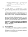
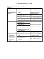
Microwave Linear Intrusion Sensor «FORTEZA-300», «FORTEZA-500» «FORTEZA-300T», «FORTEZA-500T» User manual Document Part Number 4372-43071246-003 2003 CONTENTS 1. 2. 3. 4. 5. 5.1. 5.2. 5.3. 6. 6.1. 6.2. 7. 8. 8.1. 8.2. 8.3. 9. 9.1. 9.2. 9.3. 9.4. 10. 10.1. 10.2. 11. 12. 13. Introduction ......................................................................................................... 3 Purpose ................................................................................................................ 3 Specifications ...................................................................................................... 3 Sensor components.............................................................................................. 5 Sensor structure & operation ............................................................................... 5 Sensor principle of operation .............................................................................. 5 Control and indication parts ................................................................................ 6 Sensor operation .................................................................................................. 7 Sensor construction ............................................................................................. 8 Rx construction ................................................................................................... 8 Tx construction .................................................................................................... 8 Safety measures ................................................................................................... 11 Mounting procedure ............................................................................................ 12 Requirements for the sector preparation and the alignment of Rx and Tx ........................................................................................................ 12 Sensor mounting .................................................................................................. 12 Sensor connection ............................................................................................... 14 Preparation of the sensor for operation ............................................................... 18 Sensor preparation for its operation .................................................................... 18 Alignment of Tx and Rx ..................................................................................... 18 Rx threshold adjustment ...................................................................................... 19 Check of sensor operation ................................................................................... 19 Check of technical state ...................................................................................... 20 Check of sensor operation ................................................................................... 20 Servicing.............................................................................................................. 20 Troubleshooting guide ........................................................................................ 21 Storage ................................................................................................................. 22 Transportation ..................................................................................................... 22 Certificate ............................................................................................................ 23 2 1. INTRODUCTION 1.1. The user manual contains information about the operation of the microwave sensors «FORTEZA-300», «FORTEZA-500», «FORTEZA-300T», «FORTEZA500T» (below the sensor). There is the information required for the correct operation (use, transportation, storage and maintenance) of the sensor. The following abbreviations are used in this document: Tx - transmitter Rx - receiver MK - mounting kit PSU - power supply init JB - junction box. 2. PURPOSE 2.1. 2.2. The purpose of the sensor is to protect the perimeter sectors and to detect an intruder crossing at his full height or bent (crawling) this sector. The sensor is intended for continuous round-the-clock outdoor operation at an ambient temperature: «FORTEZA-300», «FORTEZA-500» from -45˚up to+65˚C «FORTEZA-300T», «FORTEZA-500T» from -50˚ up to +60˚C and relative humidity up to 98% at the temperature +35С. 3. SPECIFICATIONS 3.1. 3.2. 3.3. There are four modifications of the sensor: «FORTEZA-300», «FORTEZA-300T», «FORTEZA-500» and «FORTEZA-500T». The recommended length of a sector for modifications: «FORTEZA-300», «FORTEZA-300T» – from 10 up to 300m «FORTEZA-500», «FORTEZA-500T» – from 10 up to 500m. The detection zone height generated by the sensor at the maximum detection zone length is not less than 1,8 m in the center of the protected sector. The detection zone width in the center of the protected sector depends on the sector length (Table 3.1.) The detection zone is a volumetric part of the protected sector, within the scope of which any movements of an intruder generate an alarm. 3 Table 3.1. 3.4. 3.5. 3.6. 3.7. 3.8. 3.9. 3.10. 3.11. Sector length, m 500 300 250 150 50 Detection zone width, m 3,5 2,7 2,5 1,9 1,0 The sensor generates an alarm when: an intruder crosses the detection zone (perpendicularly to the axis) at a speed from 0,1 up to 10 m/sec standing up straight or bended (crawling through) with the minimum detection probability of 98 %; remote control signal is transmitted to Tx; external electromagnetic field influences on Rx for its masking. There may be no alarm signal, but in this case the sensor remains functional. The alarm is generated by breaking for 3 sec minimum. This signal is sent from Rx by the yellow and pink wires marked «NC» (normally closed). The sensor generates the fault signal at: the absence of the Tx signal. the absence of supply voltage or at its reduction lower than 9 V. a failure of Rx or Tx. When the fault signal is generated, actuating optoelectronic relay contacts are constantly open till the failure cause is eliminated (yellow and pink wires marked «NC», «NC»). No «dead» zones. The sensor generates the alarm at the opening of the Rx cover, under which there are adjusters. The contacts of the blocking button are open at the cover opening. This alarm is transmitted to Rx by the green and grey wires marked «TAMPER», «TAMPER». Operating characteristics of the blocking contacts: the current up to 0,2A at the voltage up to 80 V. Input circuits of Rx and Tx have the protection from electric pickups (including thunderstorms) with the amplitude up to 900 V. If there is the possibility of electric pickups with the amplitude more than 900, it is recommended to use the lightning guard unit «LGU-4». The characteristics of the actuating optoelectronic relay are: the maximum switching current is 0,1A; the maximum voltage is 50 V; the maximum resistance is 110 Ohm in the closed condition. The sensor power supply: from 9 up to 30 VDC with the maximum pulsation of 0,02 V. The maximum current consumption is 0,04 V. The sensor operation can be controlled remotely by biasing the dc voltage of 5 …30 V at the wire marked «RC» on the Tx unit. The duration of this test is 1…3 sec. 4 3.12. 3.13. 3.14. 3.15. The sensor adapts to the environment and doesn’t generate the false alarm at: rain, snow, thick fog; solar radiation; wind speed up to 30 m/sec.; moving of objects with the linear dimensions up to 0,2 m (birds or small animals)not closer than 3m from Rx or Tx; irregularities up to ± 0, 3m; snow up to 0,9 m (without additional adjustment); grass up to 0, 4 m; the influence of ultra short waves emissions of the range 150-175 MHz and the power up to 40 W at the distance 6 m maximum. The sensor mean lifetime is 8 years. Maximum dimensions of the units without a mounting kit, mm: transmitter - 835x240x240; receiver - 835x240x240. Maximum weight of the units with a mounting kit, kg: transmitter - 5; receiver - 5. 4. SENSOR COMPONENTS The sensor delivery kit is: 1. Receiver – 1 item 2. Transmitter - 1 item 3. Mounting kit including: bracket – 2 items; buckle – 4 items; lock for the buckle – 4 items. 4. Kit of tools and accessories including: alarm cable. 5. User manual. 6. Package. 7. Power supply unit «PSU-U-24,07», junction box «JB-30» and lightning guard unit «LGU-4» are supplied at the customer’s order. 5. SENSOR STRUCTURE & OPERATION 5.1. Sensor operation principle 5.1.1. The sensor is a bistatic microwave device. 5 The sensor principle of operation is based on generate an electromagnetic field between Tx and Rx. This field forms a volumetric detection zone in the form of a long ellipsoid of rotation. The sensor registers changes of the field when an intruder crosses the protected zone. 5.1.2. An intruder crossing the detection zone causes changes of the signal amplitude in Rx. The signal passes through the amplifier and is compared with the thresholds value according to the algorithm. If the signal change on Rx input is provoked by a person passage, then Rx generates an alarm, breaking actuating relay contacts. The signal changes depend on: height and weight of the intruder, place of the sector crossing, its relief and speed of the movement. 5.1.3. The signal on Rx input can be changed under the influence of other interference factors: precipitations, vegetations, small animals, electromagnetic interference, swinging of tree branches or gates, crossing the detection zone and which are commensurable with intruder movements. Other reasons, e.g. location of extensive constructions in the detection zone or near it (fences, walls), irregularities, snow, and grass can influence on the Rx input signal. In these cases the detection zone form is distorted because of re-reflections and interferences. Multi thresholds operation algorithm permits to reduce the number of false alarms. That’s why one should observe the recommendations of the subsection 8.1! 5.2. Adjustment, control and indication parts 5.2.1. The values of the Rx thresholds are set by a user during the sensor operation and with the help of the threshold controller «MIN-MAX». The thresholding is performed by the slow rotation of the resistor axis with a screwdriver. In this case the threshold value changes from minimum (MIN) to maximum (MAX). 5.2.2. The input signal is controlled with the tester on the jack, marked "TEST" (test jack).The more the «TEST» voltage is, the more the Rx input signal is and vice versa. The sensor is operable at the «TEST» voltage from 0,1 up to 4,8 V. 5.2.3. The light indicator «PROTECTION» informs about the sensor operation mode: continuous light means the sensor standby state; the indicator switching off for 3 sec means the alarm generation. An interrupted light of the indicator «PROTECTION» is possible in the case of quick installation of the amplifier. To reduce the power consumption, the indicator «Protection» goes out after 10 min of the sensor operation in the standby state if there were no pressures on the button «AGC», turn of the thresholds controller, change of the sensor in the alarm mode. In this case the indicator disconnection doesn’t influence on the state of the relay contacts. 5.2.4. During Rx and Tx adjustment on the upper limit of the directional patterns, the amplifier changes the adjustment mode with a big time constant to the mode with a 6 small time constant by pressing the button «AGC» (automatic gain control) on Rx. In this case an express setup of the amplifier takes place in the standby state. 5.2.5. On the Rx unit the blocking button is placed in order to prevent unauthorized openings of the back panel. In the operating condition the blocking contacts are closed, at the back panel opening they are broken. The alarm cables circuits marked «TAMPER»; «TAMPER» are broken too. 5.3. Sensor operation 5.3.1. The preparation to the sensor operation is the following: - preparation of the sector; - signal cables and power supply laying; - Tx and Rx installation; - sensor connection (connection of power supply and intruder alarm loops); - alignment of Tx and Rx antennas - setup of Rx thresholds. The principles and methods of these steps are given in the items 8-10. 5.3.2. The sensor has the following operating regimes: - standby state (closed relay contacts) - alarm signal (open relay contacts) - blocking state of Rx (open blocking contacts). 5.3.3. The receiving and control device realizes the receipt and indication of alarms. The sensor operates with the receiving-control devices, which control relay contacts. 5.3.4. Periodically the remote control device checks the sensor efficiency. The constant voltage from 5 up to 30 V is biased for 1…3 sec on the Tx wire marked «RC». The beaming of Tx is interrupted for the time and then Rx generates an alarm. The alarm generation after the «RC» signal confirms the sensor operation and operability of the loop. The control frequency is assigned by the user. 5.3.5. Besides there it is necessary to check periodically the technical state of the sensor and its servicing. Recommended frequency of the checks is given in the item 11. 5.3.6. The sensor power supply is provided by the power supply unit «PSU-U-24-0,7» or by any other direct voltage source, satisfying the technical characteristics. 5.3.7. Input circuits Tx and Rx are protected from short-term overvoltage (with the amplitude up to 900 V), provoked by electromagnetic pulses (lightning discharges, switching interferences and etc.). Nevertheless it is necessary to apply the lightning guard unit «PSU-U-24-0,7» or similar units on the objects with high frequency of thunderstorms. 7 6. SENSOR CONSTRUCTION The sensor consists of separate units (Rx, Tx) placed in dust- and splash-proof enclosures. 6.1. Rx construction 6.1.1. Rx construction and its fastening elements to the support are shown in fig. 6.1. The bearing structure of Rx 1is a parabolic antenna. The exciter is fixed inside of this antenna (in the focus of parabola). The detection camera with the cover is installed on this exciter. The processing module is fixed on the sidewall inside the antenna. Rx connection to the JB or SU is realized with the cable 12 stretched through the cable entry. Rx is fixed on the support with the bracket 7 and buckles 4. At first the bracket is fixed on the support, and then Rx is fixed to the bracket with the nut 8. The opening of the cover 14 provides the access to the control, adjustment and indication elements. The arrangement and marking of the elements under the cover 14 are shown in fig. 6.2. The main operating position of Rx is shown in fig.6.1 (to the left of the support, if one looks from the emission side). In the cases when it is impossible to fix Rx on the left of the support, it can be fixed on the right of the support. In this case the plugs 3 should be installed in two holes in the upper part of the antenna, and two holes of the antennas should be opened in the lower part. It is necessary to prevent the condensate inside the antennas. 6.2. Tx Construction 6.2.1. Tx construction is generally the same as Rx construction (see fig.6.1). There are the following differences: the microwave generator is fixed on the exciter instead of the detection camera and it is connected to the modulator; cover 14, control, adjustment and indication elements are absent. 8 1-receiver (transmitter) 2-aiming plate 3-plug 4-buckle 5-buckle lock 6- round support (tube) 7- bracket 1 item; 1 item; 2 items; 2 items; 2 items; 1 item; 1 item; Fig.6.1 9 8-screw M12 9-bent washer 12 10- washer 12 11- corrugated pipe 12-cable 13- bushing 14-cover 1 item; 1 item; 1 item; 1 item; 1item; 1 item; 1 item; 1 – indicator «PROTECTION» 2 – thresholding «MIN-MAX» 3 – socket «TEST» 4 – «AGC» button 5 – blocking button 6 – marking of cable cords Fig.6.2 Note. Dear user! The manufacturer of the sensor constantly improves their quality and reliability. That’s why in some lots of the sensors there are can be design modifications unspecified in the documents delivered with the sensors. Nevertheless, the main specifications are valid. 10 7. SAFETY MEASURES 7.1. 7.2. 7.3. 7.4. 7.5. 7.6. The current safety standards for the operation with electrical facilities with the voltage up to1000 V should be observed during mounting, preventive maintenance and repair of the sensor. The sensor is supplied by a dc source of the voltage 9…30 V or by an alternatingcurrent main of 220 V with the power supply unit «PSU-U-24-0,7». That is why it is necessary to study the arrangement of high voltage elements and cables in the power supply unit beforehand. Cables should be laid, terminated and connected to the sockets only when the supply voltage is OFF. The PSU safety device should be changed only when the line supply is OFF. It is prohibited to mount and maintain the sensor at thunderstorms. Installation and maintenance of the sensor must be performed only by people, who underwent special safety trainings. 11 8. MOUNTING PROCEDURE 8.1. Requirements to the protected sector preparation and the arrangement of Rx and Tx. 8.1.1. The sector, where Tx and Rx are located, should meet the following requirements: a) height of irregularities – up to +0,3m. If irregularities exceed +0,3m, the sensor characteristics can become worse. Under these conditions the possibility of the sensor usage is defined by the trial operation. b) grass height - up to 0,4m; c) snow height - up to 0,9 m; at the sector length less than 50m – up to 1m; d) single motionless objects (e.g. posts, tree trunks without lower branches) can be situated in the detection zone at the distance of 0,5 m minimum from the detection zone axis; e) moving bushes, tree branches, gate wings and etc. should not be situated at the distance of ±1,7 m from the axis connecting Tx and Rx at the sector length less than 50m; at the distance of ±3,7 m at the sector’s length up to 250m; at the distance of ±5 m at the sector’s length up to 500m; f) the sector width should not be less than the detection zone width (see table 3.1); The sensor can be mounted if the sector width is less. The alarm of the Rx output can possibly be very weak or absent.In this case the Rx or Tx antenna is installed from the other side of the support. Besides, in some cases the sensors interference immunity can reduce. It can be detected while the trial operation; g) the sector’s length is: «Forteza-300» - from 10 up to 300m; «Forteza-500» - from 10 up to 500m; h) the sector bias isn’t restricted. 8.2. Sensor mounting 8.2.1. Mark the perimeter for the places where the supports will be mounted. To organize the continuous protected boundary, the installation of Tx and Rx isn’t permitted on adjacent perimeter sectors. The right installation on adjacent perimeter sectors is Tx and Tx, Rx and Rx. 8.2.2. Mount the supports. It is recommended to use metal or asbestos-cement tubes of 150…200mm diameter as supports. As the sensor doesn’t have «dead» zones, it is possible to mount two Tx (or two Rx) on every support of adjacent perimeter sectors. The supports can be mounted with concreting. 12 8.2.3. 8.2.4. 8.2.5. 8.2.6. 8.2.7. Other variants of the sensor installation (for example on the fence or wall) can be applied according to the protection tactics. As the fence deforms the detection zone configuration, the sensor operation depends on the place of its mounting. The example of the support installation is shown in fig. 8.1. If the sensor blocks the top of the barrier, it is recommended to fasten the support with the barrier with a solid mechanical or welded joint. The support height under the ground must be not less than 1100 mm and not less than 600 mm under the barrier. Lay the main cables according to the project of the security system. It is recommended to use cables with the core screen or metal sheath. The cable core section is chosen on condition that the supply voltage is not less than 9 V (see 3.10) for every sensor unit. It is not recommended to lay the main cables near heavy electromagnetic interference sources (power lines, antenna systems and etc.) and to use free cable cores for impulse signal transmission. Fasten the brackets 7 on the supports 6 of Tx and Rx (fig.6.1). The brackets are fastened on the supports with two buckles (position 4). Tighten the locks (position 5), fasten the bracket on the support. Cut off the buckle surpluses. Install Tx and Rx units on the brackets with the nuts 8. Stretch the cable 12 through the corrugated pipe 11. The installation of the corrugated pipe is obligatory. Install junction boxes and power supply units (if according to the project PSU are installed within the perimeter). If you use junction boxes «JB-30» and power supply units «PSU-U-24-0,7», install them on the supports together with the sensor units inside the protected perimeter. To connect the cable 12, protected with the corrugated pipe, with the JB (or PSU), one should remove one of the threaded cable connections PG9 and place the bushing 13 with the corrugated pipe 11 into the hole. It is recommended to use one «PSU-U-24-0,7» for power supply of two contiguous sensors. It should be remembered that there are five free terminal blocks in «PSU-U-24-0,7» («1», «5»). That is why, it is not necessary to install a junction box on the support with this power supply unit. Mounting elements are supplied with the delivery set of «JB-30» and «PSU-U-24-0,7». 13 1- support; 2- dowel; 3- ground; 4-concrete; 5-holes for main cable connection . Notes. 1. For A size the ground should be laid after installation works. 2. Dimensions are given in millimeters. Fig. 8.1 8.3. Sensor connection 8.3.1. Connect the necessary power, signal and remote control circuits. Rx and Tx units are connected with its own cables. The colour or marking of the cable conductors indicate their purpose. The information about cable conductors marking, colour and purpose is given in Table 8.1.Table 8.1 ATTENTION! It is categorically forbidden to «earth» the sensor circuits directly. It is necessary to use the lightning guard unit «LGU-4» 14 Table 8.1 Rx Marking Colour «+» white «-» brown «NC» yellow «NC» pink «TAMPER» green «TAMPER» grey Tx Purpose Supply voltage 9…30 V Normally closed contacts of actuating relay Marking Colour «+» white «-» brown «RC» green Purpose Supply voltage 9…30 V Remote control +5…30 V Contacts of blocking button 8.3.2. The type and rating of the terminator of the security system loop (resistor, condenser and diode) are determined by the type of the receiving-control device, with which the sensor is connected. Usually it is a resistor. The rated resistance of this resistor should take into account the resistance of the actuating relay contacts (≈10 Ohm), the lightning guard circuit (this resistor - 100 Ohm) and the resistance of the security system loop (depends on the chosen cable type and its length). 8.3.3. The contacts of the Rx blocking button («TAMPER») can be connected to the receiving-control device with a separate loop. In this case the separate signal indicates the opening of the Rx cover. The second variant is to connect the blocking contacts in series with the actuating relay contacts. In this case an alarm will be registered by one channel of the receiving-control device at the relay actuation or at the opening of the Rx cover. 8.3.4. The scheme of the sensor connection using the junction box «JB-15» is shown in Figure 8.2. The contacts of the blocking button are connected in series with the actuating relay contacts. The sensor receives a signal from the remote control (RC) 15 when an additional button is installed at the post. It is possible to install one button for several sensors. In this case the button pressing checks the operation of all sensors. The scheme of the sensor connection using the lightning guard unit «LGU-4» is shown in Figure 8.3. During the mounting of the lightning guard unit «LGU-4» it is necessary to install them near Rx (Tx) units. The best variant is to install them instead of the JB (if the quantity of the switched circuits is up to 8). The scheme of the sensor connection to the supply unit «PSU-24-0,7» is shown in Figure 8.3. Fig.8.2 16 Fig.8.3 17 Fig.8.4 9. PREPARATION OF THE SENSOR FOR THE OPERATION AND ALIGNMENT 9.1. Sensor preparation for its operation 9.1.1. Check the correctness of supply and output circuits connection. 9.2. Alignment of Tx and Rx 9.2.1. Align Tx and Rx antennas at the height of 0,5m.The height is measured from the lower antenna edge to the ground (fig.6.1). It is necessary to carry out rough and accurate Tx and Rx alignments to provide the sensor operability. 9.2.2. The rough alignment of Tx and Rx antennas: loosen the buckle 4 with the locks 5 and unlock the nuts 8 (fig.6.1); revolve the Tx (Rx) antennas with the brackets round the support, incline the antennas vertically, then direct them at each other. Use the aiming plate 2, placed on the side of the antennas; tighten the nuts 4, using the locks 5; 9.2.3. The accurate tilt alignment of Tx and Rx antennas: switch on the sensor; open the cover 14 of Rx (fig.6.1); connect the voltmeter to the Rx socket «TEST» with the alarm cable from the delivery kit with the aim to check the signal level received by Rx; press the button «АGC». Pressing it and inclining vertically Tx and Rx, find the maximum voltmeter indication. ease the button «АGC». check of the «TEST» voltage value after the alignment. If the «TEST» voltage is less than 1,2 V, it is necessary to repeat the alignment vertically and horizontally for more accurate alignment. The «TEST» voltage of 1,2 corresponds to the signal level margin of 15 dB. If the «TEST» voltage is more than 4,5 V, it is necessary to disalign Rx and Tx upwards at a 18 - small angle so the voltage does not exceed 4,5 V. Don’t desalign Rx and Tx down or aside. The sensor is operable at the «TEST» voltage from 0,1 up to 4,8 V. The boundary values of 1,2V and 4, 5V are recommended to create the signal level margin and provide long-term stable operation; lock the nuts 8; disconnect the alarm cable from the socket «TEST». 9.3. Rx thresholding 9.3.1. Set the controller «MIN-MAX» in the position MAX. Regulate the thresholds, crossing the protected sector at his full height or bent (crawling) along its whole length. It is necessary to go out of the detection zone at a distance of 1-2 m for Rx calming (otherwise the results of the previous passage will influence on the following one). When the sensor generates alarms, «PROTECTION» indicator goes out for 3-6 sec. The following passage can be done after the switching on the indicator «PROTECTION». If the signal is not generated during the passage, the controller «MIN-MAX» is turned a little counterclockwise and the alignment is continued. Do some check passes in «problem» places of the detection zone: hollows, hills, near tree trunks. Regulate the thresholds if necessary. Note. If check passages are done at a medium speed, the threshold values allow to detect an intruder moving at a speed from 0,3 up to 10 m/sec. To expand the speed range up to 0,1…10 m/sec you should conduct additional alignment crossing the sector at a speed of 0,1 m/sec. Align the thresholds very attentively as «underrating» of the thresholds might provoke a lot of false alarms; «overrating» of the thresholds might provoke failures in the sensor operation. Close the Rx cover when the alignment is finished. 9.4. Check of the sensor operation 9.4.1. For remote testing of the sensor operation it is necessary to bias the current of 5…30 V at the wire marked «RC» on the Tx unit. The current is biased from the receiving-control device to «-» (negative charge) of the sensor power supply unit. After it the sensor must generate the alarm. It is recommended to test the sensor for 2-3 days after its alignment with the aim to detect possible errors in mounting and alignment. 19 10. CHECK OF TECHNICAL STATE 10.1. Check of sensor operation 10.1.1. During the exploitation it is recommended to test the sensor operability transmitting the remote control signal («RC») 1-3 times a day. 10.2. Servicing 10.2.1. The sensor maintenance should be conducted by people, who underwent special safety trainings. 10.2.2. During the sensor exploitation it is necessary to conduct check and preventive works. 10.2.3. Every month carry out visual examination of the sensor units and the protected sector. It is necessary to check: the absence of dust, dirt, snow and ice from the side of Tx signal transmission and Rx signal reception; clean the units if necessary; the absence of foreign objects in the protected sector. 10.2.4. Every quarter: carry out all monthly works; check the cables and cable connections. 10.2.5. The grass height is controlled during seasonal works. If the grass height is over 0,4 m, the grass should be mown down. 10.2.6. If the snow height changes, false alarms can be generated because of the signal reduction at the Rx input. In this case it is necessary to remove the snow or to change the height of Tx and Rx antennas. After the height of the antennas is changed, they should be aligned. The thresholds should be aligned as described above. 20 11. TROUBLESHOOTING GUIDE List of possible troubles is given in Table 11.1. Table 11.1 Trouble Possible Cause 1. The receivingcontrol device 1. Communication line is constantly generates broken. an alarm. 2. The protective device in the PSU is blown. 3. The sensor alignment is disturbed. 4. Tx is out of order. 5. Rx is out of order. 2. False alarms. 1. Moving branches in the detection zone. 2. High grass in the detection zone. 3. Snow blanket is above the norm and reduces the input signal. 4. Animals movement in the detection zone. 5. The Rx thresholds are too low. 3. The sensor does 1. Rx thresholds are too not generate high. alarms when an intruder crosses 2. The alignment is the detection disturbed. zone. 21 Repair Check the cable integrity and the accuracy of its connection. Restore the communication line. Replace the protective device. Align Tx and Rx antennas. Replace Tx. Replace Rx. Inspect the protected sector and remove interference factors. Check the accuracy of the Rx thresholds settings. Check the accuracy of the Rx thresholds settings. Align Tx and Rx antennas. 12. STORAGE 12.1. The sensors should be warehoused in the package at an ambient temperature from +5С up to +30 С and relative humidity 85% maximum. During storage the influence of hostile environment should be prevented. 13. TRANSPORTATION 13.1. Packaged sensors can be transported by any transport (if by air transport – in pressurized modules) if they are transported in covered cars, holds or covered bodies at the distance up to 10 000 km. The boxes should be carefully stowed in order to prevent their shifting or fall in the case of jolts. 22 Microwave Linear Intrusion Sensor «FORTEZA-300», «FORTEZA-500», «FORTEZA-300T», «FORTEZA-500T» Document Part Number 4372-43071246-003 The purpose of the sensor and its specifications are given in the respective items of the user manual. 1. DELIVERY KIT The delivery kit includes: transmitter receiver mounting kit kit of tools and accessories user manual, certificate 1 item 1 item 1 kit 1 kit 1 item. 2. ACCEPTANCE CERTIFICATE The sensor «FORTEZA-300», «FORTEZA-500» («FORTEZA-300T», «FORTEZA-500T») № ________________meets performance specifications of the Document Part Number 4372-43071246-003 and it is considered as operable. Date of issue _________201 . Quality department 3. MANUFACTURER’S WARRANTIES 3.1. 3.2. 3.3. The manufacturer guarantees the conformity of the sensor specifications to the requirements of the Document Part Number 4372-43071246-003 if a user meets the service conditions and operating rules specified by the Document Part Number 4372-43071246-003. Warranty period is 3 years since the date of sale by the manufacturer. Warranty does not cover the sensors: - with broken guarantee seals; - with mechanical failures, sensors which are out of order because of natural disasters (lightning, fires or floods). Mean lifetime - 8 years. 23 Manufacturer JSC «Okhrannaya Technika» Postal address Russia, 442960, Zarechnyj, Penza region, post office box 45. Contacts Tel. +7 8412 655316 Fax. +7 8412 655316 E-mail: [email protected] The detailed information you can find at www.FORTEZA-EU.com 24