1
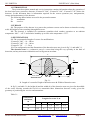
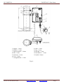
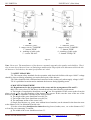
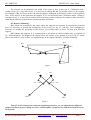
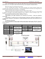
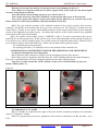
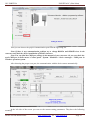
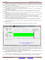
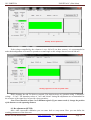
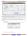
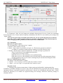
JSC FORTEZA FORTEZA PC (50m 100m ) Local Microwave Protective Detector Forteza 50, 100 PC Description Manual & Service Instruction 2013-07-01 2013 Please visit our internet sites: www.forteza.com or www.forteza.eu Page 1 JSC FORTEZA FORTEZA PC (50m 100m) CONTENTS 1. Introduction ..................................................................................................................... 3 2. Purpose ............................................................................................................................ 3 3. Specifications .................................................................................................................. 3 4. Detector Components ...................................................................................................... 4 5. Detector Structure & Operation ...................................................................................... 5 5.1. Detector Principle of Operation ................................................................................... 5 5.2. Adjustment, Control and Indication Parts .................................................................... 5 5.3. Detector Operation ....................................................................................................... 5 6. Detector Construction ..................................................................................................... 6 6.1. Rx Construction ........................................................................................................... 6 6.2. Tx Construction............................................................................................................ 6 6.3. MK (mounting kit) ....................................................................................................... 6 7. Safety Measures…………………………………………………………….…………...8 8. Mounting Procedur……………………………………………………..…………..……8 8.1. Requirements for the preparation of the sector and the arrangement of Rx and Tx …8 8.2. Detector Mounting…………………………………………………………………….9 8.3. Detector Connection……………………………………………………………….…..10 9. Preparation of the Detector for the Operation & Adjustment…………………………...11 9.1. Detector Preparation for its Operation………………………………………………...11 9.2. Adjustment of Tx and Rx ............................................................................................. 11 9.3. Rx adjustment (SETUP) ……...................................................................................... 15 10. Check of Technical State .............................................................................................. 18 10.1. Check of Detector Operation ..................................................................................... 18 10.2. Servicing ................................................................................................................... 18 11. Troubleshooting Guide.................................................................................................. 18 13. Storage ......................................................................................................................... 19 14. Transportation ............................................................................................................... 19 Certificate ............................................................................................................................ 20 Please visit our internet sites: www.forteza.com or www.forteza.eu Page 2 JSC FORTEZA FORTEZA PC (50m 100m) 1. INTRODUCTION The present description manual and service instruction contains information about the operation of the local microwave protective detectors “Forteza PC 200”, “Forteza PC 100”, “Forteza PC 50” (below the detector). In this document there is information required for the correct operation (use, transportation, storage and maintenance) of the detector. The following abbreviations are used in the present document: Tx - transmitter Rx - receiver. 2. PURPOSE 2.1. The purpose of the detector is to protect the perimeter sectors and to detect an intruder crossing at his full height or bent (crawling) through this sector. 2.2. The detector is intended for continuous round-the-clock outdoor operation at an ambient temperature -40ºC…+65С and relative humidity up to 98% at the temperature +35С. 3. SPECIFICATIONS 3.1. The recommended length of a sector for modifications: “Forteza PC 200” – 10…200 m “Forteza PC 100” – 10…100 m “Forteza PC 50” – 5…50 m 3.2. The configuration and the dimensions of the detection zone are given in fig.3.1. and table 3.1. The detection zone is a volumetric part of a sector that being the very specialty in the kind of detection, and any movement within this sector will generate an alarm. L Rx Tx h 0,85 m b 1 -2 m Axis of the Detection zone Fig.3.1. L- Length of a sector h- Height of detection zone b- Width of detection zone In fig.3.1 and table 3.1 the height (h) and the width (b) of the detection zone are given for the middle of the sector. Moving towards the receiver or transmitter these dimensions decrease evenly, given the geometry of positioning the receiver and transmitter. Table 3.1. Dimensions, maximum, m Length of a sector L, m 10 25 h b Please visit our internet sites: 0,5 0,7 50 100 200 1,4 1,6 1,8 1,0 1, 5 2, 1 www.forteza.com or www.forteza.eu Page 3 JSC FORTEZA FORTEZA PC (50m 100m) 3.3. The distance recommended from the axis of the detection zone up to guarding, building walls and other nonmoving objects should be as follows: 80…200m - 1, 1 m minimum 25…80m - 0, 8 m minimum 10…25m - 0, 4 m minimum 3.4. The detector generates an alarm when: - An intruder crosses a detection zone (perpendicularly to the axis) at a speed of 0, 3…10 m/sec at his full height or bent (crawling through) with the minimum detection probability of 98 %; An alarm is generated by breaking the contacts of an individual point opt electronic relay for the time 3 sec minimum. This signal is sent from Rx by brown and orange colored wires marked “NC” (normally closed). Note. At the distance of 3-5 m from the supports on which Tx and Rx are installed, the probability of the intruder’s detection who is bent (crawls through) is 98 % because a person can move bent and pass below the detection zone. 3.5. The detector generates a fault signal in the case: - The absence of the signal from Tx - In the absence of power supply or when the voltage drops below 9 V. - Failure of Rx or Tx. A fault signal is generated constantly (latching) till the same is rectified and indicated by break in the contacts of an individual point optoelectronic relay indicated by brown and orange colored wires marked “NC”; “NC”. 3.6. The dimensions of an individual point optoelectronic relay are: the maximum switching current is 0,1A; the maximum voltage is 50 VDC; the maximum resistance is 100 Ohm in the closed status (with the elements of storm protection). 3.7. Removal/ opening of the back inspection cover of the Rx and TX units generate a tamper alarm. The contacts of the tamper circuit are broken and this is reflected at the Rx and TX units through the black and yellow colored wires marked “TAMPER”, “TAMPER”. Contacts rating of this tamper circuit are: current up to 0,2A at voltage up to 80 VDC. 3.8. The detector power supply is: 9…30 VDC with a maximum pulsation of 0,02 V maximum. The maximum current consumption for RX and TX is 35 mA at 24 VDC. 3.9. The detector doesn’t generate an alarm when: - precipitations such as rain, snow, thick fog solar radiation the influence of wind at a speed of 30 m/sec. maximum moving of the objects in the DZ (detection zone) of 5 m from Rx or Tx of the objects with the linear dimensions of 0,2 m maximum (birds or small animals) irregularities on the sector up to ± 0, 3m snow without additional adjustment up to 0, 5 m grass up to 0, 3 m - influence of the radiated emission of ultra short waves of the range 150-175 MHz up to 40 Vat on the distance 6 m maximum. 3.10. The detector is immune to EMI: voltage impulses in supply circuits, breaks of main supply, electrostatic discharges, and electromagnetic fields. 3.11. Input circuits of Tx and Rx are protected from electric pickup (electric storm too). 3.12. The detector mean lifetime is 8 years. 3.13. Maximum dimensions of the units without a mounting kit, mm: Tx - 211*130*105 Rx - 211*130*105 3.14. Maximum weight of the units with a mounting kit, kg: Tx - 1,2 Rx - 1,2. Please visit our internet sites: www.forteza.com or www.forteza.eu Page 4 JSC FORTEZA FORTEZA PC (50m 100m) 4. DETECTOR COMPONENTS The detector delivery kit is: 1. Receiver – 1 item 2. Transmitter - 1 item 3. Mounting kit including: Bracket – 2 items Buckle – 4 items. 4. Kit of tools and accessories including: Alarm cable Key S8*10. 5. Description Manual & Service Instruction 6. Package. 5. DETECTOR STRUCTURE & OPERATION 5.1. Detector Principle of Operation 5.1.1. The detector is a bistatic microwave detector. The principle of the detector operation is to generate an electromagnetic field in the space between a transmitter and a receiver. This field provides a volumetric detection zone in the form of a long ellipsoid of rotation (see fig.3.1.). An intruder crossing a detection zone causes changes of the field. All changes of this field are recorded. There is the detection zone configuration in fig.3.1, there are given in table 3.1 its crosscuts dimensions for three performances of the detector dependency on the length of a sector with the height 0, 85 m of Rx & Tx mounting. 5.1.2. An intruder crossing a detection zone causes the change of the signal magnitude on Rx input. The signal passes through the amplifier and is compared with the value thresholds according to the algorithm. If the signal’s change on Rx input is provoked by a person passage, Rx generates an alarm breaking output contact of the relay. 5.1.3. The signal on Rx input can be changed under the influence of other factors: rain, grass, small animals, electromagnetic interference, swinging of branches, gates entering the detection zone commensurable with an intruder movement. Other reasons, e.g. location of extensive constructions, objects in the detection zone or near from it like as fences, walls, irregularities, snow, grass can influence on the level of Rx input signal. In theses cases because of big reflections and interference the detection zone configuration jumps. Multi thresholds algorithm of the detector operation permits to decrease the number of alarms provoked by interference. That’s why it is necessary to observe the recommendations in the subsection 8.1! 5.2. Adjustment, Control and Indication Parts 5.2.1. An alarm generates the values of the Rx thresholds. An explorer establishes them during the operation with the controller of the thresholds level using the software which installed in PC where detector is connected via RS-485. The thresholding is realized by the main parameter changing, can be used 2 sensitivity adjustment modes a) automatic b) manually. Manually adjustment in this case the thresholds will change from minimum to maximum value. 5.2.2. The input signal is controlled in software which installed in PC where detector is connected via RS-485. The detector keeps its operation with the range of the voltage values too: 3-290 mV. 5.2.3. The light indicator “LED” RX provides the indication of the mode operation of the detector: - Continuous luminescence means the alarm generation the standby state of the detector; - The indicator’s switching off means the standby state of the detector. 5.2.4. During Rx and Tx adjustment on the maximums of the antennas directional diagrams (Calibration mode), the amplifier is transferring from the mode of the adjustment with online mode . 5.2.5. A “normally closed” tamper loop is provided to prevent unauthorized opening of the back panel of the Rx and TX units. In the operating condition the tamper circuit’s contacts are closed, during the back panel opening they are broken. The circuits of alarm cables marked “TAMPER”; “TAMPER” (yellow and white wires) are broken too. 5.3. Detector Operation 5.3.1. The detector operation provides the following suite: Please visit our internet sites: www.forteza.com or www.forteza.eu Page 5 JSC FORTEZA FORTEZA PC (50m 100m) Preparation of the sector Signal cables and power supply laying Tx and Rx installation Detector’s connection (connection of power supply and loops of intruder alarms) Set the detection zone length Alignment of Tx and Rx antennas (Calibration) Setup of Rx thresholds and mode (automatic or manual). The principles and the methods of the operations’ performance are given in items 8-10. 5.3.2. The detector has the following operating regimes: Standby state (contact breaking) Alarm signal (open condition) Tamper state of Rx and TX (the contacts of the tamper circuit are opened). 5.3.3. The receiver control device realizes the receipt and the indication of alarms. The detector operates with the receiver control devices providing the check of the relay contacts. 5.3.4. Besides there it is necessary to check periodically the technical state of the detector and its servicing. Periodicity of the checks is given in item 11. 6. DETECTOR CONSTRUCTION 6.1. Rx Construction 6.1.1. The detector consists of separate units (Rx, Tx) placed in dust-, splash-proof enclosures. 6.1.2. Rx Construction and its fastening elements to the support are given in fig. 6.1. The carrier of the unit is base 4. Radio transparent enclosure 5 is glued to the base with sealing material. In the heel of the enclosure there are two holes preventing condensed fluid accumulation within the unit. The access to the controls, adjustment, indication elements and clamps for the connection of the terminal element is open when the cover 6 is removed. Rx is connected to the receiver control device with eight wires cable 8. Rx is mounted on the support 1 using the bracket 2 and two buckles 13. Mounting provides the rotation of the unit horizontally at angle +65 minimum; vertically: upward - at angle 30 minimum, downward – at angle 45 minimum (if the bolt 12 is eased). Location and marking of the clamps, controls, and adjustment and indication elements located under the cover 6 are shown in fig. 6.2 (a). 6.2. Tx Construction 6.2.1. Tx construction and its bracket are the same as the Rx construction (see fig.6.1). The difference is in internal elements: under cover 6 are shown in fig. 6.2 (b); six wires cables are used instead of cable 8. 6.3. MK (mounting kit) 6.3.1. Mounting kit includes two brackets and four buckles for the mounting on the support of Rx and Tx. Please visit our internet sites: www.forteza.com or www.forteza.eu Page 6 JSC FORTEZA FORTEZA PC (50m 100m) 1-support - 1 item 2- bracket - 1 item 3- figured washer - 2 items 4-base -1 item 5-enclosure - 1 item 6-cover -1 item 7- corrugated tube - 1 item 8-cable - 1 item 9-ring - 1 item 10-nut M6 - 1 item 12-bolt M6*16 – 1 item 13-buckle- 2items Fig.6.1 Please visit our internet sites: www.forteza.com or www.forteza.eu Page 7 JSC FORTEZA FORTEZA PC (50m 100m) RX 1 - indicator "LED" 2 - tamper circuit "TAMPER" 3 - buttom "PWR" 4 – marking of cable cords 5 – socket "RS 485" TX 1 - indicator "LED" 2 - tamper circuit "TAMPER" 3 - buttom "PWR" 4 – marking of cable cords 5 - buttom "FREQ CH" Fig.6.2. Note. Dear user! The manufacturer of the detector constantly upgrades their quality and reliability. That’s why in some lots of detectors one can find design modifications unspecified in the documents delivered with the detectors. Nevertheless, the main specifications are valid. 7. SAFETY MEASURES 7.1. The current safety standards for the operation with electrical facilities with up to 1000 V voltage should be observed during mounting, prevention and repair of the detector. 7.2 Cables should be laid, terminated and connected to the sockets only when supply voltage is OFF. 7.3. It is prohibited to mount and to maintain the detector during lightning storm. 8. MOUNTING PROCEDURE 8.1. Requirements for the preparation of the sector and the arrangement of Rx and Tx 8.1.1. The sector where Tx and Rx are located should meet the following requirements: a) The height of irregularities should not exceed +0,3m. If irregularities of the sector surface from the plane exceed +0,3m, the specifications of the detector can worsen. In this case the issue of the use of the detector under these conditions is defined by the trial operation. b) The height of the grass should not exceed 0,3m; c) The height of the snow should not exceed 0,5m; d) The maximum incline of the sector is 45˚; e) Single fixed objects (e.g. posts, trees without lower branches) can be situated in the detection zone at the distance of 0,5 m minimum from the axis; f) On the sector there should not be situated moving leaves, bushes, trees, etc. at the distance of 0,7 m from the axis connecting Tx and Rx; g) The width of the sector should meet item 3.3. Please visit our internet sites: www.forteza.com or www.forteza.eu Page 8 JSC FORTEZA FORTEZA PC (50m 100m) The detector can be mounted if the width of the sector is less. In this case if “Calibration mode” voltage (item 9.2.) is less than 10 mV, it is necessary to change Rx and Tx position relative to the support. For example, if Rx and Tx are at the left from the support, turning the wall bracket relative to the support at 180º, fix Rx and Tx at the right from the support. If it is not successful and “Calibration mode” voltage is less than 10 mV, it is necessary to realize the trial operation and according to its results to make a decision about the possibilities of the detector operation in these conditions. 8.2. Detector Mounting 8.2.1. Mark the perimeter for the places where the supports are mounted. To increase the protected area, it is necessary to provide the overlapping of the sectors (see fig. 8.1. and 8.2.). The overlapping is necessary to exclude the possibility of the sector’s overcoming under or above Tx (Rx) near from the support. 8.2.2. Mount the supports. It is recommended to use metal or asbestos-cement tube as supports of 50…90mm diameter. The height of the support above the surface of the ground is given in fig.6.1. In the places where there is a lot of snow, the superstructure of the support should be 1500 mm minimum. Rx3 Rx1 Rx2 Tx2 Tx1 Tx3 Fig.8.1 Tx2 Tx1 2…3 m 2…3 m Rx1 Rx2 Fig.8.2 Note: To avoid co-interference between neighboring detectors, you can adjust them to different frequencies (don’t forget to change receiver’s and transmitter’s frequency too with the mentioned way in the manual). Please visit our internet sites: www.forteza.com or www.forteza.eu Page 9 JSC FORTEZA FORTEZA PC (50m 100m) Note: Avoid installation in a way where the reflected microwave signals (by metal fences and other metal objects or by wet surfaces after rain and snow) may cause interference and false alarms. 8.2.3. The supports are mounted with concreting. The user can apply other variants of the detector mounting (for example guarding, building wall) according to the results of the trial operation. As the guarding deforms the detection zone configuration, the detector operation depends on the exact place of its mounting. 8.2.4. Lay the main cables according to the project of the security systems. Mount the brackets on the supports for Rx and Tx. The brackets of Rx and Tx (for a sector) should be adjusted. The height of the brackets mounting (if snow is absent) is chosen according to fig.6.1. The brackets are mounted on the supports with two buckles (see fig.6.1). 8.2.5. Install Tx and Rx on the brackets with bolts 12 (fig.6.1). ATTENTION! The right orientation of Tx and Rx on the bracket - drain port should be downward! ATTENTION! To reduce the level of electromagnetic interference induced on supply lines it is recommended to mount SU at the distance of 300 m maximum from the place where the detectors are installed. 8.3. Detector Connection 8.3.1. Switch ON the necessary supply voltage (supply units), signal circuits, RC-485. Rx and Tx units are connected with its own alarm cables. The wires are marked. The marking of cable conductors is given in table 8.1. Table 8.1 Rx Tx Circuit Color Purpose Circuit Color Purpose “+” red “+” red Supply voltage Supply voltage “-“ blue “-“ blue “TAMPER” yellow “TAMPER” yellow Contacts of tamper Contacts of tamper circuit circuit “TAMPER” black “TAMPER” black “NC” orange Individual point relay contacts “NC” brown “RS A” white Contacts of RS-485 connection “RS B” green Please visit our internet sites: www.forteza.com or www.forteza.eu Page 10 JSC FORTEZA FORTEZA PC (50m 100m) Warning: Do not open the detector’s housing, because it may damage the device!!! Note: Always use separated cables for the power supply circuit as the cables for the alarm signal circuit to avoid unexpected alarms. Note: The alarm contact loading capacity is up to 30 Vdc @ 0.1 A. Note: All the electronic connections should be carried out only after power is disconnected. Note: If the signal cable length is longer (more than 100 m), please use an external relay at the alarm contacts to avoid contact problems (only with standard Forteza-PC). 8.3.2. The type and the nominal of the terminal element of the security systems loop (resistor, condenser, and diode) are determined by the type of the control device. The detector is connected to the control device. Usually it is a resistor. The nominal resistance of this resistor should take into the clamping resistor of the lightning circuit (this resistor - 100 Ohm) and resistence of the security systems loop (depends on the chosen cable type and its length). 8.3.3. The contacts of the tamper circuit (“TAMPER”) of Rx or Tx can be connected to the receiver control device by the separate loop. In this case the user receives the information of the opening of the Rx or Tx terminal covers with the separate signal. The second variant: the individual point relay is switched ON in series with the contacts of the individual relay. In this case an alarm will be generated when: - the individual point relay functions; - the opening of the Rx or Tx terminal covers on one channel of the control device. 9. PREPARATION OF THE DETECTOR FOR THE OPERATION AND ADJUSTMENT 9.1. Detector Preparation for its Operation 9.1.1.Check the right connection of supply circuits and output circuits of the detector. 9.1.2. When power is supplied to detector units, the “LED” blinking indicates the signal frequency. The receiver and transmitter of a barrier should be adjusted to the same signal frequency. Note: You can only activate the “LED” indicator in the receiver and transmitter if you press bottom “PWR ( table 9.1.) Table 9.1. TX transmitter RX receiver 9.2. Adjustment of Tx and Rx 9.2.1. Tx and Rx are adjusted on the angle of the place and the azimuth according to the maximum value of “Calibration” voltage. 9.2.2. Two persons are necessary for adjustment. One of them is situated next to Rx, the other – next to Tx. Please visit our internet sites: www.forteza.com or www.forteza.eu Page 11 JSC FORTEZA FORTEZA PC (50m 100m) 9.2.3. For preliminary set-up, focus the receiver and transmitter as if a virtual direct line connects the receiver and the transmitter. The detector can be adjusted to an angle of +/- 15° degrees on any surface. Make sure that the antenna’s radiating surfaces of receiver and transmitter are parallel (radiating surface is perpendicular to the virtual direct line). 9.2.4. Transmitter signal channel adjustment In case the angle between the axes of neighboring detection zones is less than 60º, or in case reflected microwave signals, cross talk between the detectors that causes false alarms is possible. In this case it is necessary to change the signal frequency of one of the detectors (transmitter and receiver). In second point it is possible to turn the detector units by 90º to the same direction. 9.2.5 To check the number of the set channel on the Forteza PC transmitter it is necessary: Press and release the PWR button. A series of short and long signals of a buzzer sounds, which will be duplicated by light-emitting diode flashes, where the long signal and diode flash at the beginning designates an entrance to the visualization menu, and exit at the end. Short signals designate number of the installed channel. 1 Channel (1 long 1 short signal 1 long) 2 Channel (1 long 2 short signals 1 long) 3 Channel (1 long 3 short signals 1 long) 4 Channel (1 long 4 short signals 1 long) 9.2.6 To change the channel on the Forteza PC transmitter it is necessary: Hold pressed the FREQ CH button, press and releases the PWR button, then release the FREQ CH button, channel changed. Change of the channel will be confirm on following (a series of short and long signals of a buzzer will sound and it will be duplicated by light-emitting diode flashes). After ends a series of flashes of a light-emitting diode and signals of a buzzer to make actions to verification of number of the chosen channel (see point 9.2.5). If the number doesn't correspond you need to repeat operation. NOTE: Channels are changing cyclically 1-2-3-4-1, etc. 9.2.7. If the positioning is correct the “LED” indicator will be off in the receiver. Then you can start fine tuning with PC software (see PC programming part). If the “LED” indicator stays on after 30 seconds, the receiver and transmitter units should be aligned more precisely and check RX and Tx frequencies channel, they must be the same. 9.2.8. Receiver signal frequency and calibration adjustment For Forteza 50/100/200 PC detectors programming you need an RS485/USB or RS485/RS232 converter. You can choose 2 variants for connection. 1) Connect the programming extension cable throw converter to the receiver socket “RS-485” using the connection cable from RS- 485 kit. (see Table 8.1) 2) Connect the programming extension cable tusing the connection cables RS A or RS B (white and brown) from 8-cable (see Table 8.1) You can download the latest version of setup software from our website download menu http://www.forteza.com or find it on CD which is included in detector set. The alignment includes the following procedure: - Connect the Forteza 50/100/200 PC detectors throw converter to computer. - Loosen the bolts 12 (see fig.6.1) of Tx and Rx; - Go to “Calibration mode” press the button “Reset”. Stooping in turn Tx and Rx vertically exact the maximum indicated value of voltmeter. - Tighten the bolts 12 (see fig.6.1); - Loosen the nuts 10 (see fig.6.1) - Press the button “Reset”, to reset. Stooping in turn Tx and Rx horizontally exact the maximum indicated value of voltmeter. - Tighten the nuts 10 (see fig.6.1); - Check the value of “Calibration” voltage as a result of the adjustment. - After unzipping the Forteza PC adjustment software, if you double click to the downloaded software, it starts immediately (without any installation). The following initial screen will appear: Please visit our internet sites: www.forteza.com or www.forteza.eu Page 12 JSC FORTEZA FORTEZA PC (50m 100m) - Then you can choose the proper communication port from the appearing list. Note: If there is any communication problem, try to change RS485A and RS485B wires in the converter and check the driver installation of RS 485 converter.. Note: You can find the COM port settings in the manual of your converter. Or you can check the used COM port in Start menu / Control panel / System / Hardware / Device manager / COM ports in Windows operation system. After choosing the proper com port, the communication with the device starts automatically. In the left side of the screen you can see the current setting parameters. They have the following meaning: Please visit our internet sites: www.forteza.com or www.forteza.eu Page 13 JSC FORTEZA FORTEZA PC (50m 100m) Unit ID: It means the frequency modulation of the receiver. The transmitter and receiver should be on the same frequency modulation (1 ~ 4). Frequency modulation changing is only possible after entering hidden setup menu (see Hidden menu part). Mode: ‘Normal’ or ‘Alarm’ mode of the detector. There should be ‘Normal’ before fine tuning (calibration). ‘Normal’ means no alarm; ‘Alarm’ means alarm state. Zone length: The currently selected operation distance for the detector. It is really important to choose the proper operation distance. Note: If the zone length is not the real distance, there might be higher false alarm rate or poor sensitivity. Sensitivity: It means the sensitivity of detection. You can only set sensitivity in ‘Manual’ Setup method. In most of the cases sensitivity setting is not recommended. Setup method: You can choose ‘Auto’ or ‘Manual’ setup. In ‘Manual’ setup you can set sensitivity, in ‘Auto’ setup you can change ‘Zone length’. In most of the cases ‘Auto’ setting is recommended. Speed: It is the motion speed range which is identified by the detector. Speed changing is only possible after entering hidden setup menu (see Hidden menu part). Note: Too big speed range has higher false alarm rate, too low speed range has poor sensitivity. 9.2.9. Calibration. Before any setup, you need to calibrate your detector. You can make it if you select ‘Calibration’ menu. Firstly you need to calibrate (fine positioning) the transmitter unit, then the receiver unit. Here you can see the received signal from the transmitter on a dynamically changing scale. The maximum value of the current positioning is always signed. If you are close to the maximum value of the current positioning, the changing lane becomes green. It means the positioning is OK. If the lane is red, you should continue positioning as you are not close to the maximum value. With ‘Reset maximum’ button you can reset the current maximum, and you can look for another reference value. Note: Always recommended a few minutes of positioning to have a good maximum value of current positioning, what you can use as a reference. Check the value of “Calibration” voltage as a result of the adjustment. If “Calibration” voltage is less than 3 mV, it is necessary to repeat the alignment vertically and horizontally for more exact adjustment. Please visit our internet sites: www.forteza.com or www.forteza.eu Page 14 JSC FORTEZA FORTEZA PC (50m 100m) If the voltage controlled by the voltmeter is over 290 mV (on short sectors), it is recommended to make the desalignment of Rx and Tx upwards at a small angle so the voltage does not exceed 290 mV. Don’t desalting Rx and Tx down or towards. The detector keeps its operation using “Calibration” voltage …2.5 mV. The boundary values of 3 mV and 200 mV during the adjustment are recommended for the resource of the signal level to provide a long operation; Note: There should be at least 3 mV minimum signals. If you cannot reach it, change the position of the detectors or the operating distance. 9.3. Rx adjustment (SETUP) 9.3.1. After successful calibration you can come back to setup menu. Here you can define the working parameters of the detectors. Please visit our internet sites: www.forteza.com or www.forteza.eu Page 15 JSC FORTEZA FORTEZA PC (50m 100m) The most important is to set the proper ‘Zone length’ according to the installation site. Then you can set the ‘Setup method’. In ‘Manual’ setup method you can set sensitivity. But in most of the case ‘Auto’ mode and default sensitivity value is recommended. You can send your setting to the receiver with ‘Apply’ button, or you can cancel your settings with ‘Cancel’ button. Note: If the zone length is not the real distance, there might be higher false alarm rate or poor sensitivity. Save alarms: It is a useful function if the installer is alone. With this function you can count alarms, so you can check your detector with test crossings. With ‘Reset’ button you can reset the counter. In ‘Mode’ field you can see that our system is in ‘Normal /Green/’ state (it means no alarm) or ‘in Alarm /Red/’ state. 9.3.2. Hidden menu You can enter to this menu if you push F10, and write the default password (default password: 1). In this menu you can have some additional settings. Please visit our internet sites: www.forteza.com or www.forteza.eu Page 16 JSC FORTEZA FORTEZA PC (50m 100m) In ‘Parameters’ field you can change the minimum detected speed in m/s (Vmin), the maximum detected speed in m/s (Vmax), and the frequency modulation (Unit ID). You can confirm your settings with ‘Apply’ button. Note: Too big speed range has higher false alarm rate, too low speed range has poor sensitivity. Note: The receiver and transmitter of a barrier should be adjusted to the same signal frequency. Note: Changing of other parameters in this menu is not recommended. 9.3.3. Operation Detector NC signals contact The self-diagnostics of the detector has 3 signals: 1. Normal - alarm contact is closed. 2. Alarm - alarm contact is opened for at least 2 sec. The detector generates an alarm if: - a walking or crawling on hands and knees human crosses the detection zone 3. Trouble - alarm contact is opened continuously. A trouble message is generated if: - There is interference from neighboring transmitter - Voltage drops lower than 9 VDC - Either the receiver or the transmitter unit is malfunctioning - Either the receiver or the transmitter unit is blocked with non radio-transparent objects - Normal operation of the receiver unit is sabotaged by an external electromagnetic field Detector TAMPER signals contact The tamper of the detector has 2 signals: 1. Normal – cover (see Fig.6.1) is close and relay contact is closed. 2. Alarm – cover (see Fig.6.1) is open and relay contacts is open. Operation check 1. Running-in the detector means that a 24-hour testing period should be implemented after installation, preferably running for at least 3 days with all detections being registered and analyzed. During running-in detector’s operation should be checked twice a day by test crossing the detection zone. If false alarms are registered, or no alarms are registered during test crossings, check the sensitivity settings to eliminate defects. Please visit our internet sites: www.forteza.com or www.forteza.eu Page 17 JSC FORTEZA FORTEZA PC (50m 100m) 9.3.4. Verifying of interference presence To verify the absence of interference on the receiver, switch off the power supply of the transmitter, or use the test input of the transmitter. If the receiver doesn’t signal alarm in this case, there are interference problem (the receiver has signal from another transmitter). In case of interference, you can proceed as one of the following: Change the positions or the distances of the units Change frequency modulation Change the polarization, rotating 90° (around detection zone axis) in the same direction the transmitter and receiver Change technology of detection. After the detector adjustment it is recommended to carry out its trial operation for 2…3 days to reveal and eliminate possible errors of mounting and adjustment. 10. CHECK OF TECHNICAL STATE 10.1. Check of Detector Operation 10.1.1. During the detector’s exploitation it is recommended to check detection zone. Just break the detection zone 1…3 times in week. 10.2. Servicing 10.2.1. The detector should be served by the technicians after special training and instruction. 10.2.2. During the service of the detector it is necessary to conduct check and preventive works. 10.2.3. Every month carry out external examination of the detector units and the state of the sector where Tx and Rx are installed. It is necessary to check: the absence of dust, dirt, snow and ice from the side of radiation of Rx and Tx antennas and clean them if it is necessary; the absence of outside objects in the sector where Tx and Rx are installed. 10.2.4. Every quarter: carry out all the works specified as works carried out every month; check the state of the cables and cable connections. 10.2.5. During seasonal works it is controlled the height of the grass. If the height of the grass is over 0,3m the grass should be cut or removed by another method. 10.2.6. If the height of snow changes, false alarms can be generated because of the decrease of the signal at the input of the receiving unit. In this case it is necessary to remove snow or to change the height of Tx and Rx antennas installation. After the height of the antenna mounting is changed, they should be aligned. The thresholds should be adjusted according to the procedure given before. 11. TROUBLESHOOTING GUIDE List of possible troubles is given in table 11.1. Table 11.1 Trouble Possible Cause 1. The receiver control device 1. Communication line is broken. constantly generates alarms Repair Check the cable integrity and the accuracy of its connection. Restore the communication line. 2. The protective device in the Replace the protective device. supply unit is blown. 3. The detector alignment is Align Tx and Rx antennas. disturbed. 4. Tx fails. Replace Tx. 5. Rx fails. Replace Rx. 6. Channels of receiver and Check what channels was selected Please visit our internet sites: www.forteza.com or www.forteza.eu Page 18 JSC FORTEZA FORTEZA PC (50m 100m) transmitter is different. 1. Moving branches are in a detection zone and they cause alarms. 2. High grass is in the sector. 3. Snow blanket is higher than one specified in the manual and this reduces an input signal. 4. Animals circulate in the sector. 5. The Rx sensitivity is too high. 3. The detector does not generate 1. Rx sensitivity is too low. alarms when an intruder crosses the sector. 4. The receiver connection with 1. RS-485 driver installation with PC is broken. mistakes 2. If using the RS-485 connection cable 8 Fig.6.1. (white RS A, green RS B), was changed then connected. in receiver and transmitter Inspect the sector and remove interference factors. 2. False alarms of the detector Check the accuracy of the Rx sensitivity setting. Reinstall the driver. Check connection of RS A and RS B 12. STORAGE 12.1. The detectors should be stored in the package in warehouses at an ambient temperature +5С…+30 С and relative humidity 85% maximum. During storage the influence of hostile environment should be prevented. 13. TRANSPORTATION 14.1. Packaged detectors can be transported by any transport (if by plane – in pressurized modules) if they are transported in covered cars, holds or covered bodies they can be transported at the distance up to 10 000 km. The boxes should be placed to prevent their shifting or fall in case of jolts and blows. Please visit our internet sites: www.forteza.com or www.forteza.eu Page 19 JSC FORTEZA FORTEZA PC (50m 100m) Microwave Intrusion Sensor “Forteza PC 50/100/200” Certificate The purpose of the sensor and its specifications are given in the corresponding clauses of the data sheet of the Description manual and service instruction 2012-04-12. 1. DELIVERY KIT The delivery kit includes: Transmitter 1 item; Receiver 1 item; Mounting kit 1 kit; Kit of tools and accessories 1 kit; User manual, certificate 1 item. 2. ACCEPTANCE CERTIFICATE The sensor Forteza 50/100/200 PC ___________meets performance specifications of the Description manual and service instruction 2013-06-13 and it is considered as operable. Date of issue _______________ 3. MANUFACTURER’S GUARANTEES The manufacturer guarantees the conformity of the sensor specifications to requirements of the attached user manual if a user meets the service conditions and operating rules specified by the attached user manual. Warranty period is 24 months since the date of sale by the manufacturer. Guarantees do not cover the sensors: - with broken guarantee stamps; - with mechanical failures, - and also those which are out of order because of natural disasters (lightning, fire and flood). Mean lifetime is 8 years. Send complaints to the following address: European Office: JCS “Forteza”, Tilzes str. 38, 91112 Klaipeda, Lithuania Phone +370 46 441195;+370 46 411353 Fax +370 46 412231 E-mail [email protected] www.forteza.com Please visit our internet sites: www.forteza.com or www.forteza.eu Page 20