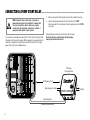
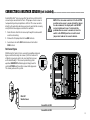
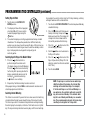
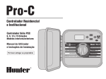
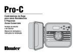
1
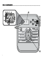
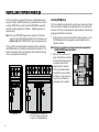
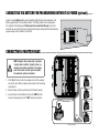
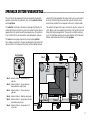
�����
��������������������������������
����������������������
��������������������������
������������������
�������������������������
�
���
�����������
�
������
������
3934%-/&&
-!.5!,n!,,34!4)/.3
�����������������������������������
-!.5!,n3).',%34!4)/.
3%405-0/0%2!4)/.
�
�����
�����������������������
3%402/'2!-34!244)-%3
���������������������
�����������������
Table of Contents..............................................................................................................
INTRODUCTION AND INSTALLATION
Introduction................................................................................................................................................................................................... 1
Pro-C Components......................................................................................................................................................................................... 2
Pro-C Components – Wiring Cabinet............................................................................................................................................................... 4
Mounting the Indoor Controller to Wall.. .......................................................................................................................................................... 6
Mounting the Outdoor Controller to Wall......................................................................................................................................................... 7
Connecting Valves and AC Power.................................................................................................................................................................... 8
Installing Station Modules............................................................................................................................................................................ 10
Connecting the Battery.. ................................................................................................................................................................................ 11
Connecting a Master Valve ........................................................................................................................................................................... 11
Connecting a Pump Start Relay..................................................................................................................................................................... 12
Connecting a Weather Sensor....................................................................................................................................................................... 13
Rain Sensor Bypass.................................................................................................................................................................................. 13
Connecting an SRR or ICR Remote Control.. .................................................................................................................................................. 14
Connecting to the Hunter ET System............................................................................................................................................................. 15
Connecting to the Hunter Irrigation Management and Monitoring System™.. ................................................................................................... 16
Power Failures.. ............................................................................................................................................................................................ 16
CONTROLLER PROGRAMMING AND OPERATION
Sprinkler System Fundamentals.................................................................................................................................................................... 17
Creating a Watering Schedule.. ...................................................................................................................................................................... 18
How to Fill Out the Watering Schedule........................................................................................................................................................... 18
Watering Schedule Form Example................................................................................................................................................................. 19
Watering Schedule Form............................................................................................................................................................................... 20
Programming Fundamentals.. ........................................................................................................................................................................ 21
Programming Fundamentals Example............................................................................................................................................................ 22
Table of Contents (continued).........................................................................................
Programming the Controller.. ........................................................................................................................................................................ 23
Setting the Current Date and Time............................................................................................................................................................. 24
Setting Program Start Times..................................................................................................................................................................... 24
Eliminating a Program Start Time.............................................................................................................................................................. 25
Setting Station Run Times (Length of Watering for Each Area)................................................................................................................... 25
Setting Days to Water............................................................................................................................................................................... 26
Selecting Specific Days of the Week to Water.. ........................................................................................................................................... 26
Selecting Interval Watering....................................................................................................................................................................... 26
Selecting Odd or Even Days to Water.. ....................................................................................................................................................... 27
Run.. ........................................................................................................................................................................................................ 27
System Off............................................................................................................................................................................................... 27
Manually Run a Single Station.. ................................................................................................................................................................. 27
Manually Run All Stations......................................................................................................................................................................... 28
One Touch Manual Start and Advance........................................................................................................................................................ 28
Seasonal Adjustment................................................................................................................................................................................ 28
Advanced Features.. ...................................................................................................................................................................................... 29
Hidden Features.. .......................................................................................................................................................................................... 30
TROUBLESHOOTING AND SPECIFICATIONS
Troubleshooting Guide.................................................................................................................................................................................. 32
Frequently Asked Questions.......................................................................................................................................................................... 34
Specifications.. ............................................................................................................................................................................................. 34
FCC Notice...................................................................................................................................................................................... Back Cover
INTRODUCTION........................................................................................................................
Finally, there’s an affordable, full-featured indoor/outdoor controller for both commercial and residential applications.
Hunter Industries is pleased to introduce the Pro-C Professional Controller for commercial and residential use. Designed with the needs of the
customer in mind, the Pro-C offers simplified dial programming and an impressive range of features.
The Pro-C is a professional grade product. The controller’s cabinet provides ample room for wiring. And the Pro-C is filled with essential features
that landscapes demand like a rain sensor bypass circuit, primary and secondary power surge protection, seasonal adjustment/water budgeting,
programmable pump/master valve circuit, programmable rain delay, three independent programs with four different day scheduling choices and
four start times each, plus much more.
The Pro-C is so easy to use that you’ll need this user guide very little after installation. If you do have a question about the controller, refer to
this booklet or to the abbreviated instructions inside the door.
You can be sure that you’ve chosen with confidence. The Pro-C is a controller that does the job efficiently and economically.
Pro-C Components..............................................................................................................
"
#
#
36/
3"*/4&/403
#:1"44
¡
"$5*7&
4:45&.0''
."/6"-o"--4 5"5*0/4
."/6"-o4*/(-&4 5"5*0/
4&516.101&3"5*0/
0RO#
4&5$633&/5%" 5&5*.&
4&5130(3".45"355*.&4
4&545"5*0/36/5*.&4
4&5%":4508"5&3
$
This section will give you a brief overview of some of the components on
the Pro-C. Each item will be discussed in further detail later, however this
section can be helpful in getting acquainted with the controller.
A. – LCD Display
1. Program Selector – Identifies the program in use A, B, or C.
2. Station Number – Identifies currently selected station number.
3. Main Display – Indicates various times, values, and programmed
information.
19. and Buttons – Used to increase or decrease the seasonal
adjust option.
A key feature of the Pro-C is its clear, easy-to-use dial design that .
makes programming a snap. All essential keypad functions are clearly
marked to eliminate the confusion that’s a characteristic of so many
other controllers.
C. – Control Dial
Run – Normal dial position for automatic and manual operation.
4. Year – Identifies current calendar year.
Set Current Date/Time – Allows current date and clock time to be set.
5. Month – Identifies current calendar month.
Set Program Start Times – Allows 1 to 4 start times to be enabled in
each program.
6. Day – Identifies current calendar day.
7. Running – Sprinkler icon indicates when watering is occurring.
8. Days of the week – Identifies days of the week to water or .
not water. You can also select odd or even and an interval watering
schedule.
9. Odd/Even Watering – Identifies if odd or even watering is selected.
10.Interval – Identifies if interval watering has been selected.
11.Seasonal Adjust – Displays in increments of 10%, the percentage
of seasonal adjust that has been selected.
12.Start Time – Identifies selected start time. (Only appears on LCD
main display when “Set Program Start Times” is selected.)
B. – Control Buttons and Switches
13.
Set Station Run Times – Allows user to set each station run time.
Set Days to Water – Allows user to select individual days to water or
to select an odd, even, or interval watering schedule.
Set Pump Operation – Allows user to turn off pump or master valve
for specific stations.
Manual – Single Station – Allows user to activate a one time watering
of a single station.
Manual – All Stations – Allows user to activate a one time watering of
all stations or a few selected stations in a selected program.
System Off – Allows user to discontinue all programs and stop all
watering until the dial is returned to the RUN position, or to set the
programmable rain off feature.
Button – Increases the selected flashing display.
14.
Button – Decreases the selected flashing display.
15.
Button – Returns selected flashing display to the previous item.
16. Button – Advances the selected flashing display to the .
next item. Also to start a manual cycle.
17.
Button – Selects programs A, B, and C. Also to start .
a test program.
18.Rain Sensor Switch – Allows user to bypass weather sensor, if
one is installed.
Pro-C Components – Wiring Cabinet.........................................................................
22
21
20
24
23
27
26
25
D. – Wiring Compartment
20. 9-Volt Battery – An alkaline battery (not included) allows you to
program the controller without AC power.
21. Reset Button – This button will reset the controller. .
All programmed data will remain intact.
22. Power Area – Used to attach transformer, sensor wires, and other
systems from their source to the controller.
23. Transformer – A transformer is installed in the controller to
route AC power from the power cable to the terminal strip area.
(Outdoor models only, indoor models are supplied with a plug-in
transformer.)
24. Junction Box – This box provides an area for connecting primary
power. (Outdoor models only.)
25. Station Modules – There are 3 open module positions inside the
controller. With the addition of up to 3 PCM-300 modules, you can
run 3 to 12 stations. The addition of 1 PCM-300 and 1 PCM-900
(9-station module) will increase station capacity to 15 stations.
Note: T he use of a PCM-900 to expand your controller to 15 stations
requires that one PCM-300 be installed in the first slot .
(stations 4-6) and the PCM-900 in the upper two slots.
26.Base Module – Includes terminals for stations 1 through 3, the
master valve (pump connection), and the common wire.
27.Power-Lock Slide – The Power-Lock feature will turn off power
and unlock modules for removal. Once all modules have been
installed, sliding the Power-Lock to the “ON” position activates
power and locks modules in their expansion slots.
MOUNTING THE Indoor CONTROLLER TO A WALL........................................................
All necessary hardware is included for most installations.
NOTE: The indoor Pro-C is not weather or water
resistant, and must be installed indoors or in a
protected area. This device is not intended for use
by young children. Never let children play with
this device.
B
A
1. Select a location as close as possible to a standard electrical outlet
that is not controlled by a light switch. The location should be
protected from moisture and direct sunlight. A 15 foot distance is
recommended between the controller and any other electrical device
to prevent the possibility of electrical interference.
2. Remove the front panel from the Pro-C by first removing the ribbon
connector and then pulling down the hinge release and removing the
ribbon connector. Removing the front panel will ease installation of
the controller cabinet.
3. Place the controller at eye level. Use the hole at the top of the
controller as a reference and secure one 25mm screw (A) into
the wall. Note: Install screw anchors if attaching to drywall or
masonry wall.
4. Align controller with the screw and slide the keyhole (B) on top of the
controller over the screw.
5. Secure controller in place by installing screws in the holes (C).
NOTE: Do not plug transformer into power source
until the controller is mounted and all valves have
been connected.
C
MOUNTING THE Outdoor CONTROLLER TO A WALL....................................................
NOTE: Outdoor model is water and weather
resistant. Connecting the outdoor Pro-C to the
primary power should be done by a licensed
electrician following all local codes. Improper
installation could result in shock or fire hazard.
This device is not intended for use by young
children. Never let children play with this device.
A
C
1. Select a location that is conveniently close to a power supply. A 15
foot distance is recommended between the controller and any other
electrical device to prevent the possibility of electrical interference.
2. Make sure to abide by all electrical and installation codes when
attaching to an external wall.
3. Remove the front panel from the Pro-C by first removing the ribbon
connector and then pulling down the hinge release and removing
the front panel. Removing the front panel will ease installation of the
controller cabinet.
4. Place the controller at eye level and align keyhole (A) on top of the
controller and mark the spot as well as the three holes (B) on the
bottom of the unit.
5. Drill a 6 mm hole at each mark.
6. Install screw anchors (C) into holes if attaching controller to .
drywall, masonry, or plaster walls.
7. Holding the controller cabinet, line up the holes in the cabinet with
the wall anchors or pilot holes.
8. Drive a screw through each hole and secure but do not over tighten.
For PC-301-A:
B
If the supply cord is damaged, it must be replaced by the manufacturer
or service agent or a similarly qualified person in order to avoid hazard.
CONNECTING VALVES and AC Power...............................................................................
1. Route valve wires between control valve location and controller.
Indoor Cabinet
2. At valves, attach a common wire to either solenoid wire of all valves.
This is most commonly a white colored wire. Attach a separate
control wire to the remaining wire of each valve. All wire splice .
connections should be done using waterproof connectors.
Route transformer cable through the hole on the bottom left side of the
controller and connect the Yellow Wires to the screws marked AC and
the Green Wire to GND. Before closing the compartment door make sure
wires hang in the slotted areas so that the door can snap shut without
damaging wires.
3. Open hinged faceplate on the controller to access the terminal .
strip area.
4. Route valve wires through the conduit and attach conduit to the
controller at the large conduit opening on the right side of the bottom
of the cabinet. Refer to the conduit sizing chart on page 34 in the
Frequently Asked Questions section if you are not sure what size
conduit will work for your installation.
5. Strip ½" (13 mm) of insulation from ends of all wires.
Secure valve common wire to “COM” (Common)
terminal on the first module. Then attach all individual
valve control wires to appropriate station terminals.
Valve 4
Valve 3
Transformer
Valve 2
3 Wires
AC2
AC1
GND
Yellow
Yellow
Green
Connect the Two Yellow
Transformer Wires to
the Two AC Terminals
and the Green Wire to
the GND Terminal
Valve
Wires
Valve Common Wire
Valve 1
NOTE: It is recommended that a licensed
electrician perform the following power
installation.
Valve 4
Valve 3
Outdoor Cabinet
Route AC power cable and conduit through the ½" .
(13 mm) conduit opening on the left side of the bottom of
the cabinet. Connect the wires to the transformer wires
located inside the junction box. International units are
supplied with a built in terminal strip. Always use a UL
listed conduit ½" (13 mm) male adapter when installing .
the AC wiring. Insert the adapter (male threads first) into
the ½" hole at the bottom of the controller until it enters the
wiring enclosure. Attach the nut to the adapter inside the
enclosure.
Valve 2
Valve
Wires
Valve 1
Valve Common Wire
NOTE: Illustration shows international terminal strip. Domestic units
are supplied with wires that must be
connected with wire nuts or other locally
approved connectors.
110 VA C
(Domestic Models Only)
230 VAC
(International Models Only)
½" Conduit
for AC Power
INSTALLING STATION MODULES.........................................................................................
The Pro-C controller is supplied with a factory-installed base module
for up to 3 stations. Additional modules may be added in increments of
3 stations (PCM-300) or a single 9-satation (PCM-900) to expand the
controller’s station capability to 15 stations. Additional modules are
sold separately.
Note: T he use of a PCM-900 to expand your controller to 15 stations
requires that one PCM-300 be installed in the first expansion slot
(stations 4-6) and the PCM-900 in the upper two expansion slots.
The Pro-C utilizes automatic module recognition firmware to identify
when PCM modules are installed or removed from the controller. This
feature will recognize the correct number of stations without having to
reset or cycle power to the controller.
Installing PCM Modules
The Pro-C controller is designed with a simple to use Power Lock feature
that assures that the modules are energized and firmly secured into the
controller. The Power Lock can unlock or lock all modules at one time by
simply pushing the Power Lock slide. 1. Slide the Power Lock into the Power Off (unlocked) position. Insert
the PCM modules into the appropriate sequential position in the
controller cabinet.
Note: Your Pro-C controller is designed to work only in conjunction
with BLACK PCM expansion modules.
2. Once all of the modules are in
place, slide the Power Lock into
the Power On (locked) position
to energize and secure the
modules into the controller.
3. The Pro-C will automatically
recognize the correct number
of stations. It is not necessary
to press the reset button or
cycle power to the controller.
PCM-300
10
PCM-900 (Must be installed in the .
9-12 station module slots and used
along with one PCM-300 Module)
CONNECTING THE BATTERY For Programming Without AC Power (optional)...........
Connect a 9-volt alkaline battery (not included) to the battery terminals and place in the
battery compartment in the controller cabinet. The battery allows the user to program
the controller without AC power. Watering will not occur without AC power. Since this
controller has non-volatile memory, the program clock and calendar will be retained during
a power outage even if no battery is installed.
7PMU#BUUFSZ
CONNECTING A Master Valve...........................................................................................
NOTE: Complete this section only if you have
a master valve installed. A master valve is a
normally closed valve installed at the supply
point of the main line that opens only when
the automatic system is activated.
Valve 4
1. At the Master Valve, attach the common wire to either solenoid .
wire of the valve. Attach a separate control wire to the remaining
solenoid wire.
Valve 3
2. Route the wires into the controller via the field wire conduit.
3. Connect either wire from Master Valve to the P/MV terminal. .
Connect remaining wire to the “COM” (Common) terminal.
Valve 2
Master Valve Wire
Valve
Wires
Valve 1
Master Valve
Valve Common Wire
11
CONNECTING A PUMP START RELAY..................................................................................
1. Route a wire pair from the pump relay into the controller housing.
NOTE: Complete this section only if you have a
pump and pump start relay installed. A pump start
relay is an electronic device that uses a signal
current from the irrigation controller to activate a
pump to provide water to your system.
2. Connect the pump common wire to the terminal slot “COM”
(Common) and the remaining wire from the pump relay to the P/MV
screw slot.
The controller should be mounted at least 15 feet (4.5 m) away from both
the pump start relay and the pump. When a pump is to be operated by the
controller, a pump start relay must be used. Hunter offers a full range a
pump start relays for most applications.
Relay holding current draw must not exceed .28 amps. .
Do not connect the controller directly to the pump –
damage to controller will result.
PSR Series
Pump Start Relay
15’ Minimum (4.5 m)
High Voltagle in to Relay
Pump Relay Wire
Pump Relay Common Wire
12
To Pump
CONNECTING A WEATHER SENSOR (not included)...........................................................
A Hunter Mini-Clik ® rain sensor or other type of micro-switch weather
sensor may be connected to the Pro-C. The purpose of a rain sensor is
to stop watering when precipitation is sufficient. The sensor connects
directly to the controller and allows you to easily override the sensor by
using the Rain Sensor bypass switch on the controller.
1. Route the wires from the rain sensor up through the same conduit
used for valve wiring.
2. Remove the flat jumper from the two SEN terminals.
NOTE: If the rain sensor switch is left in the ACTIVE
position and no sensor is connected and the jumper
has been removed, the display will read SEN OFF
and no irrigation will occur. To eliminate this
problem when no sensor is connected, leave the
switch in the BYPASS position or install a short
jumper wire between the sensor terminals.
3. Connect one wire to the SEN terminal and one to the other
SEN terminal.
Rain Sensor Bypass
With this built-in feature, there is no need for an additional manual
bypass switch when using rain sensors (the Pro-C works with
all Hunter sensors, plus other rain, wind, and freeze sensors
3"*/4&/403
#:1"44
on the market today). If the sensor is preventing system
operation SENSOR OFF will be displayed. Simply move the
"$5*7&
switch to BYPASS and the weather sensor will be bypassed.
4:45&.
This allows you to use the system.
Mini-Clik ®
Weather Sensor
Sensor Wire to SEN
Sensor Wire to SEN
13
CONNECTING A WEATHER SENSOR (continued)...............................................................
Testing a Weather Sensor
The Pro-C provides simplified testing of a rain sensor when the rain
sensor is wired into the sensor circuit. It also provides the user the
ability to override the rain sensor when necessary to perform system
inspections and manual watering.
•
•
Overriding the Rain Sensor
Use of a Hunter remote control (single station operation only, .
not programs A, B, or C) and manual single station function on the
Pro-C dial will override the rain sensor. This function provides the
users the ability to operate the system even though the rain sensor
has shut the system off.
Testing the Rain Sensor
The user can manually test the proper operation of the rain sensor
by running a manual “all stations cycle” or by activating the
system using the one touch manual method (see page 28). During
the manual cycle, pressing the test button on the Mini-Clik ® will
interrupt the watering indicating proper sensor operation.
CONNECTING AN SRR OR ICR REMOTE CONTROL (not included).................................
The Pro-C controller is shipped with a SmartPort ® wiring harness,
allowing for fast and easy use of the Hunter SRR, or Long Range ICR
remote controls. The SRR and ICR make it possible for contractors and
end users alike to operate a system without having to walk back and forth
to the controller.
To utilize the SRR or ICR Remote
Control System you must install
the SmartPort connector (supplied
with your Pro-C controller).
5P$POUSPMMFS
5ISFBE
14
1SFBTTFNCMFE
4. Access the terminal strip area and
attach the red wire to the bottom most
AC screw slot, attach the white wire to
the upper AC screw slot and attach the
blue wire to the screw slot .
marked REM.
#MVF
8IJUF
3FE
The SmartPort is now ready for remote
control use. Please refer to either the
SRR or ICR owner’s manual for further
information or contact your local Hunter distributor for ordering
information.
1. Install a ½" female threaded
“Tee” in the field wiring
conduit approximately 12"
below the Pro-C.
2. Feed the red, white, and blue
wires of the harness through
the base of the “Tee” and into
the wiring compartment as
shown in Fig. 1.
3. Screw the SmartPort harness .
housing into the “Tee” as shown .
in Fig.1.
"TTFNCMFE
NOTE: Any extension of the wiring on the SmartPort ®
may result in an error message in the controller
display and possible malfunction of the remote
unit due to radio interference. In some situations,
lengthening of the harness may work fine, in others
it may not work at all (it is site specific). In either
case, extending the wiring harness should be done
using shielded cable to minimize the possible
effects of electrical noise. For easiest installation,
order a new Hunter SmartPort shielded cable wiring
harness (part #SRR-SCWH) with a full 25 feet of
shielded cable.
Indoor Installation
Outdoor Installation
(Temporary Connection
of Receiver Only)
C���������
R�������
CONNECTING TO THE HUNTER ET SYSTEM
The Hunter ET System allows irrigation programs to be created
automatically, based on local climate conditions. These programs are
then loaded into the controller and run automatically. ET System uses
sensor to determine the local “evapotranspiration” (ET) rate of turf and
plants. The result is a new, water-efficient irrigation program every water
day, based on local weather conditions. For more information on the ET
System, contact your local Hunter dealer.
&54&/403
�����������
���
�
������
������
3934%-/&&
-!.5!,n!,,34!4)/.3
-!.5!,n3).',%34!4)/.
3%405-0/0%2!4)/.
�����
�����������������������
&5.0%6-&
3%402/'2!-34!244)-%3
���������������������
�����������������
15
CONNECTING TO THE HUNTER IRRIGATION
MANAGEMENT and monitoring SYSTEM™............................................................................
With the Irrigation Management and Monitoring System™ (IMMS™),
automatic irrigation systems at multiple sites or multiple controllers .
on a single site can be programmed for functions that would typically .
be handled directly at each site’s controller. Scheduling of days to water,
run times, start times, cycle and soak operations, and more can now .
be done from a single computer at a desk miles away from the .
actual installation.
In addition, scheduled operation of non-irrigation components also in
use at these sites – e.g., lighting systems at athletic fields, fountains
at shopping centers – as well as pumps and sensors can also be
programmed and monitored from a single central location.
No system available today is more cost-effective than the Hunter IMMS.
It’s inexpensively priced and contains the most essential features needed
for water management. It’s able to team with any or all of the standard
automatic controllers in the Hunter line-up, from the SRC to the Pro-C to
the ICC. Plus, it’s a system that’s easy and affordable to upgrade, making
it possible to accommodate an expanding network of controllers.
For more information on the IMMS, contact your local Hunter dealer.
A key function of the IMMS is its ability to monitor changing conditions.
With the aid of such options as flow sensors, rain sensors, and other
weather-sensing devices, the IMMS can receive reports on the current
condition at every site it is linked with and then respond with the
necessary adjustments should any of those conditions go beyond the
limits that have been defined..
POWER FAILURES...............................................................................................................................
Due to the possibility of power failures, the controller has non‑volatile
memory to preserve the program indefinitely. There is no default program.
The Pro-C is also capable of keeping the current time and date for an
extended period of time during power outage conditions.
16
SPRINKLER SYSTEM FUNDAMENTALS..............................................................................
There are three main components that are involved with all automatic
sprinkler systems that are made today. They are the controller, valves,
and the sprinklers.
of water that can be pumped to the location. Each valve is connected via
wire to the terminal strip area inside of the controller. Here the wire is
connected to a number that corresponds to the valve’s station number.
The controller is what makes the whole system operate efficiently. It is
technically the brain of the entire system, instructing the valves when to
supply water to the sprinklers and for how long to do so. The sprinklers,
in turn, will direct the water towards the surrounding plants and lawn.
The controller will operate the valves in numerical sequence, only one at
a time. When a valve has completed its watering; it will switch to the next
station that has been programmed. This process is called the watering
cycle. The information pertaining to the watering times of the individual
stations and the duration of them is called a program.
The valve controls a group of sprinklers called a watering station. .
These stations are laid out in a fashion according to the type of plant life
that exists there, the locations of the plants, and the maximum amount
1SP$$POUSPMMFS
36/
#:1"44
¡
"$5*7&
4:45&.0''
."/6"-o4*/(-&4 5"5*0/
4&516.101&3"5*0/
0RO#
7BMWF
7BMWF
4UBUJPO
¡
3"*/4&/40 3
."/6"-o"--4 5"5*0/4
7BMWF
4&5$633&/5%" 5&5*.&
¡
4&58"5&3*/(45"355*.&4
4&545"5*0/36/5*.&4
4&5%":4508"5&3
4UBUJPO
¡
7BMWFo "DUJWBUFT4UBUJPOo3PUPSTXBUFSGSPOU
ZBSEMBXO
4UBUJPO
7BMWFo "DUJWBUFT4UBUJPOo4QSBZTXBUFSTJEF
MBXOBOECVCCMFSTXBUFSnPXFST
7BMWFo "DUJWBUFT4UBUJPOo3PUPSTXBUFSCBDL
ZBSEMBXO
7BMWFo "DUJWBUFT4UBUJPOo#VCCMFSTXBUFSHBSEFO
¡
¡
7BMWFo "DUJWBUFT4UBUJPOo4QSBZTXBUFSTJEFMBXO
BOECVCCMFSTXBUFSnPXFST
7BMWFo "DUJWBUFT4UBUJPOo4QSBZTXBUFSGSPOU
DPSOFSMBXO
4UBUJPO
7BMWF
4UBUJPO
¡
4UBUJPO
7BMWF
7BMWF
17
CREATING A WATERING SCHEDULE....................................................................................
For most consumers, it is much easier to plan your specific watering
schedule onto paper before actually programming the information .
into the controller. It’s also handy to have a written record of your .
programming information for easy reference.
There are some guidelines that should be followed when determining
when and how long to water. These factors are the soil type, the part
of the landscape being watered, weather conditions, and the types of
sprinklers being used. Since there are so many different variables that
can determine your individual watering schedule, it is impossible to give
an exact schedule to follow. However, we have included some guidelines
to help you get started.
NOTE: It is usually good to water one or two hours
before sunrise. Water pressure will be at optimum
levels during the early morning and the water can
soak into the roots of the plants while evaporation
is minimal. For most plants, watering during midday or in the evening may cause plant damage or
possibly mildew.
NOTE: Keep an eye out for evidence of under- or
over-watering. Over-watering is most commonly
indicated by pools of water that take a long time
to soak in or evaporate, while under-watered
landscapes will show signs of discoloring and
dryness. Make programming changes immediately
when evidence is present.
HOW TO FILL OUT THE WATERING SCHEDULE.................................................................
Be sure to use a pencil when filling out this form. By using the included
example and the information below, you should have all the information
you need to construct your personal water schedule.
Station Number and Location – Identify the station number, location and
the type of plant that is being watered.
Watering Day – Identify whether you want to use a calendar day, interval,
or an odd or even day schedule. For a calendar day schedule circle the
day of the week in which watering is desired. For an interval schedule,
indicate the desired interval number.
18
Program Start Times – Indicate the time of day that the program will
begin. Each program can have 1-4 start times. However, one start time
will run an entire program. Write “OFF” for any Pump Start Time not
used.
Station Run Time – Indicate the run time (1 minute – 6 hours) for .
each station. Write “0:00” for any station that you do not want to operate
in the program.
Keep this schedule in a safe place for quick reference later, rather than
scrolling through program information on the controller.
Watering Schedule Form example............................................................................
19
Watering Schedule Form................................................................................................
)6/5&3130$
%":0'5)&8&&,
*/5&37"-$IPPTFUPEBZT
130(3".
45"355*.&4
45"5*0/
-0$"5*0/
/05&4
20
130(3"."
45"5 *0/36/5*.&
130(3".#
45"5 *0/36/5*.&
130(3".$
45"5 *0/36/5*.&
PROGRAMMING FUNDAMENTALS......................................................................................
A watering program can be created to operate valves in numerical
sequence one at a time. All that is required to create a watering
program is to:
1. Select a program (A, B, or C) by pressing the
button on the
controller (it is recommended to start with Program A).
2. Set a program start time (only one program start time is required to
activate a watering program).
3. Set the run time for each valve assigned to the program, and
4. Set the days that you would like the watering program to run.
We have included an example that will better illustrate the operation of
a program:
Let’s say you have a program start time set for 6:00 a.m. Stations 1 and 2
are going to have a run time of 15 minutes and station 3 is set for 20
minutes. Please note that stations 4, 5, etc. have not been included in
this program, we will water them on separate programs.
Going back to our previous example, at 6:00 a.m. the controller will
activate the watering cycle. The sprinklers on station 1 will run for
15 minutes and then shut off. The controller will automatically advance
to station 2 sprinklers. These sprinklers will also run for 15 minutes and
then shut off. Then, watering on station 3 will begin. The sprinklers will
turn on for 20 minutes and shut off. Since no times were programmed
for stations 4, 5, etc. the controller skips them. This will conclude the
program and end the water cycle at 6:50 a.m.
As shown in the above example, only one program start time was
required to run the three different stations. The controller automatically
moves to the next station without the need for additional start times.
We realize that many consumers will have variations in their plant
watering needs, so at Hunter we equipped the Pro-C with three different
programs A, B, and C. These programs are independent of each other.
However, no two programs can run at the same time. The Pro-C will
automatically stack any programs that overlap. Programs scheduled to
run at the same time will run in alphabetical order.
21
PROGRAMMING FUNDAMENTALS example...................................................................
LOCATION
Front Lawn
Shrub
Side Yard
15 min.
12
1st.Program
Start.Time.at
6:00.AM
9
3
6
Sprinklers.On
Station.1.begin.to
water.at.6:00.AM
Automatically
advances.to
next.station
Sprinklers.Off
Station.1.turns.off
at.6:15.AM
Station 2
15 min.
12
9
3
6
Sprinklers.On
Station.2.begin.to
water.at.6:15.AM
Automatically
advances.to
next.station
Sprinklers.Off
Station.2.turns.off
at.6:30.AM
Station 3
20 min.
®
12
®
9
3
6
Total Cycle of Program A = 50 minutes
22
Station 1
®
1
2
3
4
5
6
7
8
9
10
11
12
NOTES:
Program A
S
®
STATION
1
2
3
4
PROGRAM A
W T F S
Every 1 day
7:00 AM
OFF
OFF
OFF
STATION RUN TIME
15 minutes
15 minutes
20 minutes
T
®
PROGRAM
START TIMES
M
®
��HUNTER PRO-C
DAY OF THE WEEK
ODD/ EVEN or INTERVAL
Sprinklers.On
Station.3.begin.to
water.at.6:30.AM
Sprinklers.Off
Station.3.turns.off
at.6:50.AM
Cycle
Ends.at
6:50.AM
PROGRAMMING THE CONTROLLER....................................................................................
Two key features of the Pro-C that make programming a snap are its
clear, easy-to-read LCD display and its easy-to-use dial design.
The Pro-C display shows time and day when the controller is idle. .
The display changes when the dial is rotated to indicate the specific
programming information to enter. When programming, the flashing
portion of the display can be changed by pressing the
or
buttons.
To change something that is not flashing, press
or
until desired
field is flashing.
BYPASS
®
ACTIVE
SYSTEM OFF
MANUAL – ALL STATIONS
MANUAL – SINGLE STATION
SET PUMP OPERATION
NOTE: A basic programming rule is that whatever
symbol or character is flashing will be the item
programmed. For instance, if the hour is flashing
when setting the time, the hour can be changed or
programmed. For illustration purposes, flashing
characters are in GRAY type.
To activate a program in your controller, you must enter the following
information:
RUN
RAIN SENSOR
watering, perfect for the establishment of new lawns and thirsty annual
flowers. A built in 365-day calendar clock accommodates odd/even
watering restrictions without requiring monthly reprogramming. .
Or, just simply designate the days of the week you want to water or use
the convenient day interval watering.
Pro-C
SET CURRENT DATE / TIME
SET PROGRAM START TIMES
SET STATION RUN TIMES
SET DAYS TO WATER
1. Set current day and time – turn dial to set current date/time.
2. Set what time of day you would like the program to start – turn dial to
SET PROGRAM START TIMES.
3. Set how long each valve will water – turn dial to set station
run times.
4. Set the day(s) you would like the program to water – turn dial to
set days to water.
NOTE: All stations operate in numerical order. Only
one program start time is required to activate a
watering program.
The Pro-C controller offers maximum scheduling flexibility including
three programs, each with up to 4 daily start times, permitting plants
with different watering requirements to be separated on different day
schedules. Multiple start times permit morning, afternoon and evening
23
PROGRAMMING THE CONTROLLER (continued)...............................................................
Setting the Current Date and Time
1. Turn the dial to the SET
CURRENT DATE/TIME position.
2. The current year will be flashing
in the display. Use the
and
buttons to change the year. After
setting the correct year, push the
button to proceed .
to setting the month.
3. The month and day will be in the display.
The month will be flashing. Use the
and
buttons to change the month.
Press the
button to proceed to
setting the day.
4. The day will be flashing: Use the
.
and
buttons to change the day of the
month (The day of the week is automatically selected.) Press the
button to
proceed to setting the time.
5. The time will be displayed: Use the .
and
buttons to select AM, PM, .
or 24 hr. Press the
button to move .
to hours. Hours will be flashing. Use .
the
and
buttons to change the
hour shown on the display. Press the
button to move onto the minutes.
Minutes will be flashing. Use the
and
buttons to change the minutes
shown in the display. The date, day, .
and time have now been set.
24
4&5$633&/5%"5&5*.&
Setting Program Start Times
1. Turn the dial to the SET
PROGRAM START TIMES
position.
2. The factory preset is set on
program A. If necessary you
can select program B or C by
pressing the
button.
SET PROGRAM START TIMES
3. Use the
and
buttons to change
the start time. (Advances in 15-minute
increments.) One start time will
activate all stations sequentially in
that program. This eliminates the need
to enter a start time for each station.
Multiple start times in a program
can be used for separate morning,
afternoon, or evening watering cycles.
4. Press the
button to add an additional start time, or
the next program.
button for
NOTE: Regardless of the order in which the
start times are entered, the Pro-C will always
arrange the start times in chronological order
when the dial is moved off the SET PROGRAM
START TIMES position.
Eliminating a Program Start Time
Setting Station Run Times (Length of Watering for Each Area)
With the dial set to the SET
PROGRAM START TIMES
position, push the
and
buttons until you reach .
12:00 am (Midnight). From this
position push the
button
once to reach the OFF position.
1. Turn the dial to the SET
STATION RUN TIMES position.
SET PROGRAM START TIMES
NOTE: If a program has all four start times
turned off, then that program is off (all other
program details are retained). Because there are
no start times, there will be no watering with that
program. This is a convenient way to stop watering
on one program only without turning the dial to the
off position.
2. The display will show the last
program selected (A, B, or C) .
the station number selected, and
the run time for that station will
be flashing. You can switch to
another program by pressing .
the
button.
4&545"5*0/36/5*.&4
3. Use the
and
buttons to change
the station run time on the display.
4. Press the
button to advance to the
next station.
5. Repeat steps 4 and 5 for each station.
6. You may set station run times from 1 minute to 6 hours.
7. You can move between programs while staying on the same station.
However, it is recommended that one program is completed before
going on to the next program. Jumping between programs can be
confusing and may result in program errors.
25
PROGRAMMING THE CONTROLLER (continued)...............................................................
Setting Days to Water
For example if you select an interval of 3 with 1 day remaining, watering
will begin tomorrow at the scheduled time.
1. Turn the dial to the SET DAYS TO
WATER position.
2. The display will show the last program
selected (A, B, or C). You can switch
to another program by pressing the
button.
1. Turn the dial to SET DAYS TO WATER. The water drop above Monday
should be flashing.
4&5%":4508"5&3
3. The controller displays currently programmed active day schedule
information. This dial position provides four different water day
options: you can choose to water on specific days of the week, or you
can choose interval watering, or choose to water on odd days or even
days. Each program can only operate using one type of .
water day option.
Selecting Specific Days of the Week to Water
1. Press the
button to activate a .
particular day of the week to water .
(the display always starts with Monday).
Press the
button to cancel watering
for that day. After pressing a button the
display automatically advances to the
next day. A indicates a water day. .
A indicates a no water day.
2. Repeat step 1 until desired days have been selected.
After programming, set dial to RUN to enable automatic execution of all
selected programs and start times.
Selecting Interval Watering
This feature is convenient if you want to have a more consistent watering
schedule without having to worry about the day of the week or the date.
The interval you select is the amount of days between watering including
the watering day. For example, an interval of 3 will water once every third
day. The days remaining indicates how many days until the next watering.
26
2. Press the
button until the drop over
Sunday is flashing, then press the
button one more time. The display will
change to the interval mode and the
Interval Day number will be flashing.
3. Press the
or
button to select the
Interval Day(s) you desire.
4. Push the
button once to advance to
the Days Left number.
5. Press the
or
button to select the
Days Left you desire (0 Days left is the
water day and will run the next available
Start Time).
6. Turn the dial to RUN.
NOTE: If any days are selected as non-water days
at the bottom of the display, the Interval Day
watering will exclude those days. For example,
if the Interval Days are set at 5 and Monday is a
non-water day, the controller will water every 5th
day, but never on a Monday. If the interval water
day falls on a Monday and Monday is a non-water
day. The program would not water for 5 more days
resulting in no irrigation for 10 days total.
36/
Selecting Odd or Even Days to Water
Run
This feature uses a numbered day of the month for watering instead of
specific days of the week (odd days 1st, 3rd, 5th, etc.; even days 2nd,
4th, 6th, etc.).
After programming is complete, turn the dial to
RUN to enable automatic execution of all selected
programs and start times.
1. Using the instructions for Interval Watering, set the interval to one.
System Off
2. When in the interval mode the days
along the bottom of the display indicate
No Water Days. The icon indicates
no watering for that day. Press the
button until the cursor is on either EVEN
or ODD in the display. Select whichever
you choose as No Water Days by pressing the
button. If you
select ODD as No Water Days then the controller will only water on
even days of the month. Conversely, if you select EVEN as No Water
Days then the controller will only water on odd days of the month.
Valves currently watering will be shut
off after the dial is turned to the SYSTEM
OFF position for two seconds. All active
programs are discontinued and watering
is stopped. To return controller to normal
automatic operation, simply return dial to
RUN position.
ODD
= will water on EVEN Days / = will water on ODD Days
You can also set particular days of the week as no water days using
this feature (see Advanced Features on page 30).
3. Turn the dial to the RUN position to enable automatic watering.
NOTE: The 31st of any month and February 29th are
always “off” days if Odd watering is selected.
4:45&.0''
Manually Run a Single Station
1. Turn the dial to the MANUAL-SINGLE STATION position.
2. Station run time will flash in the
display. Use the
button to
move to the desired station. .
You may then use the
and
buttons to select the
amount of time for a station to
water.
."/6"-o4*/(-&45"5*0/
3. Turn the dial to the RUN position to run
the station (only the designated station
will water, then controller will return to
automatic mode with no change in the
previously set program).
NOTE: This function will override the sensor.
27
PROGRAMMING THE CONTROLLER (continued)...............................................................
Manually Run All Stations
1. Turn the dial to MANUAL-ALL
STATIONS.
One Touch Manual Start and Advance
."/6"-o"--45"50/4
2. You can select program A, B, or
C by pressing the
button.
3. Press the
button until desired
starting station is displayed.
4. Station run time will flash in the display.
Use the
and
buttons to select
the amount of run time for the station
to water if different from the run time
displayed.
5. Use the
button to move to the .
next station.
6. Repeat steps 3 and 4 to customize each
station if desired.
7. Press the
button until desired
starting station is displayed.
8. Return the dial to RUN (custom program
will water the entire program beginning
with the station number last left in the
display, then controller will return to
automatic mode with no change in the
previously set program).
NOTE: The station that is on the display when
you turn the dial to RUN, will be the first station
to run. The controller will then proceed to
water in sequential order only. It will not water
previous stations.
28
You can also activate a program to water without
using the dial.
1. Hold down the
button for 2 seconds. 2. This feature automatically defaults to program
A. You can select program B, or C by pressing
RUN
the
program.
RAIN SENSOR
BYPASS
ACTIVE
®
Pro-C
3. The station number will be flashing.
Press the or
button
to scroll
MANUAL – ALL STATIONS
SET PROGRAM START TIMES
through the stations and use the
MANUAL – SINGLE STATION
SET STATION RUN TIMES
and
buttons to adjust the station run
times. (If no buttons areSETpressed
during
SET DAYS TO WATER
PUMP OPERATION
step 2 or 3, the controller will automatically begin program A.)
SYSTEM OFF
SET CURRENT DATE / TIME
4. Press the
button to scroll to the station you wish to begin with.
After a 2 second pause, the program will begin.
This feature is great for a quick cycle when extra watering is needed or
if you would like to scroll through the stations to inspect your system.
Seasonal Adjustment
Seasonal Adjust is used to make global
run time changes without re-programming
the entire controller. This feature is
perfect for making small changes that are
necessary as the weather changes without
reprogramming the entire controller. For
instance, hotter times of the year may
require a bit more water. Seasonal adjust
can be increased so that the stations
will run longer than the programmed
time. Conversely, as Fall approaches, the
seasonal adjust can be reduced to allow for
short watering durations.
4FBTPOBM"EKVTU
#VUUPOT
4FBTPOBM"EKVTU
%JTQMBZ
To use the seasonal adjust, simply press the up or down seasonal
adjust buttons to set the percentage desired. Each bar on the graph
can be adjusted from 10% to 150% of original program. The season
adjust can be changed at any time regardless of the programming dial
position. To view the new adjusted run time, simply turn the rotary dial
to the Set Run Times position, the displayed run time will be updated
accordingly as the seasonal adjustment is made.
NOTE: The controller should always be initially
programmed in the 100% position.
Advanced Features............................................................................................................
2) Programmable Rain Off
There are three advanced features
available to customize the Pro-C to
more complex watering requirements.
One of these features is “hidden” to
make accidentally programming them
nearly impossible.
1) Set Pump/Master Valve Operation
4&516.101&3"5*0/
The default is for all stations to have
the master valve/pump start circuit
ON. The master valve/pump start can be
set ON or OFF by station, regardless of
which program the station is assigned. This
feature may be utilized on systems where
it is desirable for a booster pump not to
operate with certain zones.
To program pump operation:
1. Turn the dial to SET PUMP OPERATION position.
2. Press the
or
buttons to toggle the master valve/pump start ON
or OFF for the specific station.
3. Press the
4:45&.0''
This feature permits the user to stop all
programmed waterings for a designated
period from 1 to 7 days. At the end of the
programmable rain off period, the controller
will resume normal automatic operation.
button to advance to the next station.
4. Repeat steps 2 and 3 for all necessary stations.
1. Turn the dial to the SYSTEM OFF position.
2. Press the
button and a 1 will be
displayed and the DAYS LEFT icon will
illuminate. The 1 will be blinking at
this point.
36/
3. Press
as many times as needed to set the
number of days off desired (up to 7).
4. To validate this setting (and to make sure the
controller comes back on after the period is
over), turn the dial back to the RUN position at
which time, OFF, a number and the DAYS icon all
remain on.
5. Leave the dial in the RUN position.
The days off remaining will decrease at
midnight of each day. When it goes to zero,
the display will show the normal time of day
and normal irrigation will resume at the next
scheduled start time.
29
Advanced Features (continued).......................................................................................
3) Setting Specific Day(s) Off
Programming in a No Water Day(s) is useful to inhibit watering
on mowing days, etc. For instance, if you always mow the lawn on
Saturdays you would designate Saturday as a No Water Day so you .
are not mowing wet grass.
1. Turn the dial to the DAYS TO WATER
position.
4. Use the
button until the cursor is at
the day of the week you wish to set as a
No Water Day.
5. Press the
button to set this day as a
no water day. The will illuminate over
this day.
6. Repeat steps 4 and 5 until all desired event day(s) are off.
2. Enter an interval watering schdule as
described on page 26.
3. With the days left flashing, press
button to display the days of the
week. MON will be flashing.
4&5%":4508"5&3
Hidden FeatureS..................................................................................................................
1) Programmable Delay Between Stations
36/
This feature allows the user to insert a delay
between when one station turns off and the next
station turns on. This is very helpful on systems
with slow closing valves or on pump systems that
are operating near maximum flow or have slow
well recovery.
4. Press the
and
buttons to increase
or decrease the delay time between 0 and 59
seconds in 1 second increments and then in
one minute increments up to four hours. Hr
will be displayed when the delay changes from
seconds to minutes and hours.
1. Start with the dial in the
RUN position.
2. Press and hold the
button
down while turning the dial to
the SET STATION RUN TIMES
position.
30
button. At this point
3. Release the
the display will show a delay time for
all stations in seconds, which will be
blinking. The DELAY icon shall also be lit
at this time.
5.R eturn the dial to the RUN position.
4&545"5*0/36/5*.&4
36/
NOTE: The Master Valve/Pump Start circuit
will operate during the first 15 seconds of any
programmed delay to aid in the closing of the valve
and to avoid unnecessary cycling of the pump. It
is recommended that a pressure relief valve be
installed on the system should this one minute be
too long for a particular system. Consult your pump
contractor or supplier for details.
problems). Press the
button to begin the Quick Check test procedure.
Within seconds, the system searches all stations in an effort to detect
a high current path through the station terminals. When a field wiring
short is detected, an ERR symbol preceded by the station number
will momentarily flash on the controller LCD display. After the Hunter
Quick Check completes running this circuit diagnostic procedure, the
controller returns to the automatic watering mode.
4) Clearing Controller’s Memory/Resetting Controller
2) Test Program
The Pro-C allows the user a simplified method for running a test
program. This feature operates each station in numerical sequence, .
from the lowest to the highest. You can start with any station. This is a
great feature to check the operation of your irrigation system.
To initiate the test program:
1. Press and hold the
button. The station number will be flashing.
2. Press the
or button to scroll to the station you would like the
test program to start with. Use the
and
button to set a run
time of up to 15 minutes. The run time needs to be entered only once.
3. After a 2 second pause, the test program will begin.
3) Hunter Quick Check™
Irrigation professionals are continuously looking for ways to more
efficiently and effectively diagnose programs in the field. Instead
of having to physically check each field wiring circuit for potential
problems, the user can run the Hunter Quick Check™ circuit test
procedure. This circuit diagnostic procedure is very beneficial because
of its ability to aid in quickly identifying “shorts” commonly caused by
faulty solenoids or when a bare common wire touches a bare station
control wire.
To initiate the Hunter Quick Check test procedure; Press the
,.
,
and
buttons simultaneously. In the standby mode, the
LCD will display all segments (helpful when troubleshooting display
If you feel that you have misprogrammed the controller, there is a
process that will reset the memory to factory defaults and erase all
programs and data that have been entered into the controller. Press the
,
, and the
buttons simultaneously and hold them down, while
they are being held down, press and release the RESET button on the
back of the front panel. Then release the ,
, and the
buttons.
The display should now show 12:00 am. All the memory has been cleared
and the controller may now be reprogrammed.
WINTERIZING YOUR SYSTEM
In regions within the country where the frost level falls below the
depth of the installed piping, it is common for these systems to be
“winterized”. Several methods can be used to drain the water from the
system. If the blow out method is used it is recommended that a qualified
licensed contract perform this type of winterization.
WARNING! WEAR ANSI APPROVED SAFETY EYE PROTECTION!
Extreme care must always be taken when blowing out the system with
compressed air. Compressed air can cause serious injury, including
serious eye injury from flying debris. Always wear ANSI approved safety
eye protection and do not stand over any irrigation components .
(pipes, sprinklers, and valves) during blow out. SERIOUS PERSONAL
INJURY MAY RESULT IF YOU DO NOT PROCEED AS RECOMMENDED.
31
TROUBLESHOOTING GUIDE...................................................................................................
32
PROBLEM
CAUSES
SOLUTIONS
The controller repeats itself or continuously waters, even when it should not be
on (cycling repeatedly).
Too many start times (user error).
Only one start time per active program is
required. Refer to “Setting Program Start
Times” on page 24.
There is no display.
Check AC power wiring.
Correct any errors.
The display reads “ERR”.
Electrical noise is entering the system.
Check the SmartPort® wiring harness. If
the wires were extended then they will need
to be replaced with shielded cable. Contact
your local distributor for information on
shielded cable
The display reads “P ERR”.
There is a fault in the wire to the pump start
or master valve.
Check the master valve or pump start wire
for continuity. Replace or repair the shorted
wire. Check that all wire connections are
good and water tight.
The display reads a station number and
ERR, such as “2 ERR”.
There has been a fault with the wire leading
to that station.
Check the station wire for continuity. Replace
or repair shorted wire. Check that all wire
connections are good and water tight.
The display reads “NO AC”.
There is no AC power present (the controller
is not receiving power).
Check to see if the transformer is properly
installed.
PROBLEM
CAUSES
SOLUTIONS
The display reads “SENSOR OFF”.
The rain sensor is interrupting irrigation or
the sensor jumper is not installed.
Slide the Rain Sensor switch on front panel
to the BYPASS position to bypass rain
sensor circuit, or install the sensor jumper.
Rain sensor will not shut off system.
Incompatible rain sensor or the jumper was
not removed when sensor was installed.
(Man. 1 Station Override)
Make sure sensor is micro-switch type such
as Mini-Clik® (Rain Bird® Rain Check is not
this type and will not work). Check that the
the jumper has been removed from the the
SEN terminals. Confirm proper operation
(see "Testing a Weather Sensor" on page 14).
The controller does not have a start time
for each station.
Programming error, dial in incorrect .
position.
Be sure the dial is in correct position. Total
number of stations can be easily checked
by placing diai in SET STATION RUN TIMES
position and pressing the back arrow.
Valve will not turn on
Short in wiring connections..
.
Bad solenoid..
.
Power-Lock Slide in “Power OFF” position.
Check field wiring..
.
Replace solenoid..
.
Slide Power-Lock to “Power ON” position
(see page 10).
33
Frequently asked Questions........................................................................................
WHAT SIZE FIELD WIRING CONDUIT SHOULD I USE?
Locate the size conduit across the top and the wire size along the side.
Where the two intersect on the table tells you approximately how many
wires will fill the conduit.
Wire Size
18 AWG
16 AWG
14 AWG
12 AWG
CONDUIT SIZES
¾" (19 mm)
12
10
6
5
For Frequently Asked Questions visit our website at
www.HunterIndustries.com
1" (25 mm)
20
16
10
7
SPECIFICATIONS......................................................................................................................
Operating Specifications
Dimensions
• Station Run Time: 1 minute to 6 hours on programs A, B, and C.
•
Start Times: 4 per day, per program, for up to 12 daily starts.
•
Watering Schedule: 7-day calendar, interval watering up to a 31-day
interval or true odd or even day programming, made possible by the
365-day clock/calendar.
Electrical Specifications
• Transformer Input: 120VAC, 60Hz (230VAC, 50/60 Hz .
International Use)
• Transformer Output: 25 VAC, 1.0 amp
• Station Output: 24VAC, .56 amps per station
• Maximum Output: 24VAC, .84 amps (includes Master Valve Circuit)
• Battery: 9-volt alkaline battery (not included) used only for .
non-AC programming, the non-volatile memory maintains .
program information
34
Indoor Cabinet
Height: 8.25"
Width: 9.5"
Depth: 3.75"
Outdoor Cabinet
Height: 9".
Width: 10".
Depth: 4.5"
Default Settings
All stations are set to zero run time. This controller has a non-volatile
memory that retains all entered program data even during power
outages, without need for a battery.
information about your sprinkler system.........................................................
Date of Installation:_ _________________________________________________________________________________________
Contractor Installing System:___________________________________________________________________________________
Address:___________________________________________________________________________________________________
_________________________________________________________________________________________________________
Phone:____________________________________________________________________________________________________
Location of Control Valves:_ ___________________________________________________________________________________
_________________________________________________________________________________________________________
Location of Weather Sensor:___________________________________________________________________________________
_________________________________________________________________________________________________________
Location of Main Water Supply Shutoff:_ _________________________________________________________________________
FCC NOTICE................................................................................................................................
This controller generates radio frequency energy and may cause interference to radio and television reception. It has been type tested and found to
comply with the limits for a Class B computing device in accordance with the specifications in Subpart J of Part 15 of FCC Rules, which are designed to
provide reasonable protection against such interference in a residential installation. However, there is no guarantee that interference will not occur in a
particular installation. If this equipment does cause interference to radio or television reception, which can be determined by turning the equipment off
and on, the user is encouraged to try to correct the interference by one or more of the following measures:
• Reorient the receiving antenna
• Move the controller away from the receiver
• Plug the controller into a different outlet so that controller and receiver are on different branch circuits
If necessary, the user should consult the dealer or an experienced radio/television technician for additional suggestions. The user may find .
the following booklet prepared by the Federal Communications Commission helpful: “How to Identify and Resolve Radio-TV Interference Problems.”
This booklet is available from the U.S. Government Printing Office, Washington, D.C., Stock No. 004-000-00345-4 (price – $2.00)
Hunter Industries Incorporated • The Irrigation Innovators
1940 Diamond Street • San Marcos, California 92078
www.HunterIndustries.com
© 2006 Hunter Industries Incorporated
P/N 700761
LIT-329
3/06