1
MITSUBISHI
Electronic Multi-Measuring Instrument
Programming Manual (CC-Link)
For ver.1 remote device station
Model
ME96NSR-MB or ME96NSR with Optional Plug-in Module : ME-0040C-NS96
ME96SSH-MB or ME96SSR-MB with Optional Plug-in Module : ME-0040C-SS96
LEN080334B
CONTENTS
1.
2.
3.
General Description............................................................................................................................... 3
Specification .......................................................................................................................................... 4
Configuration Conditions of CC-Link System ........................................................................................ 5
3.1
Remote net ver.1 mode.................................................................................................................. 5
3.2
Remote net ver.2 mode.................................................................................................................. 6
4. Programming......................................................................................................................................... 8
4.1
Programming Procedure ................................................................................................................ 8
5. Parameter Settings................................................................................................................................ 9
5.1
Procedure from Parameter Settings to Data Link Startup .............................................................. 9
5.1.1
CPU Parameter Area and Master Module Parameter Memory............................................ 9
5.1.2
Procedure for Parameter Settings to Data Link Startup with GX Developer ........................ 9
5.2
Example of Parameter Settings with GX Developer..................................................................... 10
5.2.1
Master Station Network Parameter Settings...................................................................... 10
6. Communication Between the Master Station and ME96 ..................................................................... 14
6.1
Communication Guideline ............................................................................................................ 14
6.2
Initial Communication................................................................................................................... 15
6.3
Error Communication ................................................................................................................... 15
6.4
Normal Communication................................................................................................................ 16
7. Remote I/O and Remote Register ....................................................................................................... 17
7.1
Remote Input RX, Remote Output RY ......................................................................................... 17
7.1.1
Remote input RX ............................................................................................................... 17
7.1.2
Remote Output RY ............................................................................................................ 19
7.2
Remote Register (RWr, RWw)...................................................................................................... 21
7.2.1
Supported Commands....................................................................................................... 24
7.2.2
Details of Commands ........................................................................................................ 25
7.2.3
Data format........................................................................................................................ 40
7.2.4
Multiplying Factor .............................................................................................................. 50
7.2.5
About Error Occurrence..................................................................................................... 51
8. Abbreviations and Special Terms ........................................................................................................ 52
9. Program Example................................................................................................................................ 53
9.1
Program Content.......................................................................................................................... 53
9.2
System Configuration................................................................................................................... 53
9.3
Device Allocation.......................................................................................................................... 54
9.4
Parameter Settings ...................................................................................................................... 55
9.4.1
Network Parameter Settings and Auto Refresh Parameter Settings ................................. 55
9.4.2
Operational Settings .......................................................................................................... 56
9.4.3
Station Information Settings............................................................................................... 56
9.5
Program Example ........................................................................................................................ 57
10. Test Mode............................................................................................................................................ 66
10.1 ME96SSH-MB/ME96SSR-MB...................................................................................................... 66
10.2 ME96NSR .................................................................................................................................... 67
(2/n)
LEN080334B
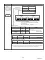
1. General Description
This manual describes the programming methods that should be created by the user for monitoring
measurement value of the Electronic Multi-Measuring Instrument (called ME96 from here on) with the
Control & Communication Link (abbreviated as CC-Link from here on).
In programming, read the following related manuals in addition to this mannual.
Table 1.1 Related Manuals
Manual Name
Manual No.
CC-Link System Master/Local Module User's Manual
type QJ61BT11
CC-Link System Master/Local Module User's Manual
type QJ61BT11N
MELSEC-L CC-Link System Master/Local Module User's Manual
FX2N-16CCL-M USER'S MANUAL
FX3U-16CCL-M USER'S MANUAL
User’s Manual for ME96
SH-080016
(13JL91)
SH-080394E
(13JR64)
SH-080895ENG
(13JZ41)
JY992D93101
(09R710)
JY997D43601
(09R724)
Supplied with product
or download.
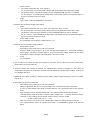
NOTICE
When using ME96, Optional Plug-in Module “ME-0040C-NS96” or “ME-0040C-SS96” is necessary.
CC-Link communication is not available without the optional plug-in module. In this manual, “ME96NSR”,
“ME96SSH-MB” or “ME96SSR-MB” means the main device of ME96 with the optional plug-in module.
POINT
ME96SSH-MB/ME96SSR-MB must be handled after setting of the remote device station version. Set the
remote device station version with the “Setting Menu 2” of the ME96SSH-MB/ME96SSR-MB.
Use the following as a guideline in setting the remote device station version and set the version at ME96.
Mode select setting
Guideline for selection
Ver.1 remote device station
Select this when utilizing the conventional program, because of
(Ver.1 compatible slave station)
compatibility with ME96NSR.
Ver.2 remote device station
Select this when configuring a new system or the being newly
(Ver.2 compatible slave station)
added to the existing system in combination with the applicable
master module.
This programming manual is for ver.1 remote device station.
For use in the ver.2 remote device station (Ver.2 compatible slave station), refer to the following manual.
・Electronic Multi-Measuring Instrument Programing Manual (CC-Link)(For ver.2 remote device station)
..................................................................................................................................................... LEN130391
(3/n)
LEN080334B
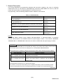
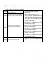
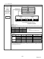
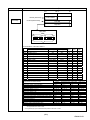
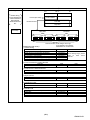
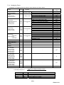
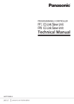
2. Specification
ME96 specification is shown in Table 2.1.
Table 2.1 CC-Link Specification
Item
Specification
CC-Link station type
Number of occupied stations
Maximum number of stations
per master station
Transmission speed
Remote I/O (RX, RY)
Remote register (RWw, RWr)
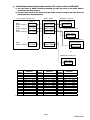
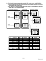
Remote device station (ver.1 remote device station)
1 station
42 stations ( In case of connecting only remote device
station occupied by 1 station.)
156kbps/625kbps/2.5Mbps/5Mbps/10Mbps
32 points each
4 points each
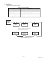
Master
station
ME96
ME96
ME96
Maximum number of connection is 42.
(In case of ME96 connection.)
ME96
ME96
ME96
System Configration (CC-Link)
(4/n)
LEN080334B
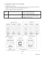
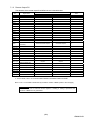
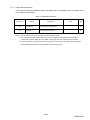
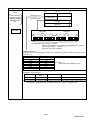
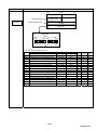
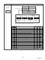
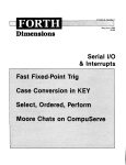
3. Configuration Conditions of CC-Link System
3.1 Remote net ver.1 mode
A total of 64 remote I/O stations, remote device stations, local stations, standby master stations, or
intelligent device stations can be connected to a single master station.
However, the following conditions must all be satisfied.
Condition 1
{(1×a)+(2×b)+(3×c)+(4×d)} ≦ 64
Condition 2
{(16×A) + (54×B) + (88×C)} ≦ 2304
a: Number of modules occupying 1 station (ME96 is applied)
b: Number of modules occupying 2 stations
c: Number of modules occupying 3 stations
d: Number of modules occupying 4 stations
A: Number of remote I/O stations ≦64
B: Number of remote device stations (ME96 is applied) ≦42
C: Number of local stations, standby master stations and
intelligent device stations ≦26
ME96NSR
ME96SSH-MB/SSR-MB
(5/n)
LEN080334B
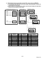
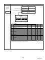
3.2 Remote net ver.2 mode
A total of 64 remote I/O stations, remote device stations, local stations, standby master stations, or
intelligent device stations can be connected to a single master station.
However, the following conditions must all be satisfied.
{(a+a2+a4+a8)
+(b+b2+b4+b8)×2
Condition 1
+(c+c2+c4+c8)×3
+(d+d2+d4+d8)×4}≦64
[{(a×32)+(a2×32)+(a4×64)+(a8×128)}
+{(b×64)+(b2×96)+(b4×192)+(b8×384)}
Condition 2 +{(c×96)+(c2×160)+(c4×320)+(c8×640)}
+{(d×128)+(d2×224)+(d4×448)+(d8×896)}]
≦8192
[{(a×4)+(a2×8)+(a4×16)+(a8×32)}
+{(b×8)+(b2×16)+(b4×32)+(b8×64)}
Condition 3 +{(c×12)+(c2×24)+(c4×48)+(c8×96)}
+{(d×16)+(d2×32)+(d4×64)+(d8×128)}]
≦2048
Condition 4 {(16×A) + (54×B) + (88×C)} ≦ 2304
a: The total number of ver.1 compatible slave stations that
occupy 1 station, and ver.2 compatible slave stations
that occupy 1 station which are set to “Single”.
(ME96 is applied)
b: The total number of ver.1 compatible slave stations that
occupy 2 stations, and ver.2 compatible slave stations
that occupy 2 stations which are set to “Single”.
c: The total number of ver.1 compatible slave stations that
occupy 3 stations, and ver.2 compatible slave stations
that occupy 3 stations which are set to “Single”.
d: The total number of ver.1 compatible slave stations that
occupy 4 stations, and ver.2 compatible slave stations
that occupy 4 stations which are set to “Single”.
a2: The number of ver.2 compatible stations that occupy 1
station which are set to “Double”.
b2: The number of ver.2 compatible stations that occupy 2
stations which are set to “Double”.
c2: The number of ver.2 compatible stations that occupy 3
stations which are set to “Double”.
d2: The number of ver.2 compatible stations that occupy 4
stations which are set to “Double”.
a4: The number of ver.2 compatible stations that occupy 1
station which are set to “Quadruple”.
b4: The number of ver.2 compatible stations that occupy 2
stations which are set to “Quadruple”.
c4: The number of ver.2 compatible stations that occupy 3
stations which are set to “Quadruple”.
d4: The number of ver.2 compatible stations that occupy 4
stations which are set to “Quadruple”.
a8: The number of ver.2 compatible stations that occupy 1
station which are set to “Octuple”.
b8: The number of ver.2 compatible stations that occupy 2
stations which are set to “Octuple”.
c8: The number of ver.2 compatible stations that occupy 3
stations which are set to “Octuple”.
d8: The number of ver.2 compatible stations that occupy 4
stations which are set to “Octuple”.
A: Number of remote I/O stations ≦64
B: Number of remote device stations (ME96 is applied)
≦42
C: Number of local stations, standby master stations and
intelligent device stations ≦26
(6/n)
LEN080334B
ME96NSR
ME96SSH-MB/SSR-MB
(7/n)
LEN080334B
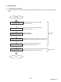
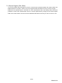
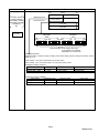
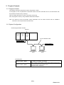
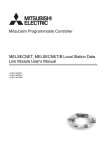
4. Programming
4.1 Programming Procedure
Create a program which executes the “Monitoring of the measurement valus” by following the procedure
below:
START
Parameter setting
Set the CPU parameter to start the data link.
(Refer to Section 5)
Selecting Commands
Select the command to transmit to the ME96.
(Refer to Section 7.2.2)
Initial Communication
Initialize the ME96.
(Refer to Section 6.2)
Normal Communication
Error Communication
Convert the data
Required
Transmit and receive the command to monitor the
measurement value. (Refer to Section 6.4,Section 7.2.2)
Check the error status flag and error code.
(Rerer to Section6.3, Section 7.2.5)
Convert the measurement data using the effective range
and multiplying factor. (Refer to Section 7.2.2)
In nesessary
End
(8/n)
LEN080334B
5. Parameter Settings
5.1 Procedure from Parameter Settings to Data Link Startup
The following explains the procedure from setting the parameters to stating the data link.
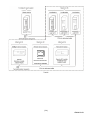
5.1.1
(1)
CPU Parameter Area and Master Module Parameter Memory
CPU Parameter Area
This area is used to set the basic values for controlling the programmable controller system and the
network parameters that control the CC-Link system.
(2)
Master Station Parameter Memory
This area stores the network parameters for the CC-Link system.
When the module is powered OFF or the programmable controller CPU is reset, the network
parameters are erased.
Programmable controller CPU
Parameter area
CC-Link system
network
parameter area
5.1.2
Master station
Parameter memory
Power ON
CPU reset
CC-Link system
network
parameter area
Procedure for Parameter Settings to Data Link Startup with GX Developer
Follow the procedure below for parameter settings to data link startup:
GX Developer
The GX Developer is
used to create
network parameters
and automatic refresh
parameters, which
are then written to the
programmable
controller CPU.
When the
programmable controller
system is powered ON
or the programmable
controller CPU is reset,
the network parameters
in the programmable
controller CPU are
transferred to the master
station and the data link
is automatically started.
Programmable controller CPU
Master station
CC-Link system
parameter area
Parameter memory
Network
parameters
Network
parameters
Network
parameters
Automatic refresh
parameters
Automatic refresh
parameters
GX Developer
Programmable controller CPU
CC-Link system
parameter area
Network
parameters
Network
parameters
Automatic refresh
parameters
Automatic refresh
parameters
Master station
Parameter memory
Network
parameters
(9/n)
LEN080334B
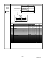
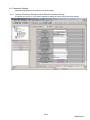
5.2 Example of Parameter Settings with GX Developer
This section explains the parameter settings using the GX Developer. For more details on the GX
Developer operation, refer to the GX Developer Operating Manual. The explanations in this section are
based on the following example of the system configuration.
Master station
(X00 to X1F)
(Y00 to Y1F)
5.2.1
Station number 1
Station number 2
ME96
(occupies
1 station)
ME96
(occupies
1 station)
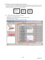
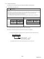
Master Station Network Parameter Settings
1) Double-click on the “Network param”.
2) Double-click on the “CC-Link” on the “Network parameter” screen.
3) Set the parameters as required.
The follwing describes an example of the parameter settings.
3)
1)
2)
(10/n)
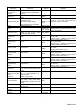
LEN080334B
Setting Item
No.of boads in
module
Start I/O No
Operational settings
Type
Example for
settings
Description
Set the "No. of boards in module "
for which the network parameters
are to be
set.
Set the "Start I/O No." for the master
station.
Set the following:
・Parameter name
・Data link err station setting
・Case of CPU Stop setting
・Block data assurance per station
Set the station type.
Set the CC-Link mode.
Mode
All connect count
Remote input
(RX)
Remote output
(RY)
Remote register
(RWr)
Remote register
(RWw)
Special relay
(SB)
Special register
(SW)
Retry count
Automatic
reconnection station
count
Standby master
station No.
PLC down select
Scan mode setting
Delay information
setting
Station information
settings
Set the total number of connected
stations in the CC-Link system
including reserved stations.
Set the remote input (RX) refresh
device.
Set the remote output (RY) refresh
device.
Set the remote
refresh device.
register
0000
Refer to next
page.
Set the link special register (SW)
refresh device.
Set the number of retries for "Retry
count", when a communication error
occurs.
Set the number of modules that can
return to system operation by a
single link scan.
Set the station number for the
standby master station
Set the data link status for "PLC
down select", when a master station
programmable controller CPU error
occurs.
Set whether the link scan for the
sequence scan is synchronous or
asynchronous.
Set for the link scan delay time.
Even if the Parameter
name is not set, this will not affect the
operation of the CC-Link system
Master station
Remote net
(Ver.1 mode)
“Remote net ver.2 mode “ and “Remote net
additional mode” can be also used in case
of the QJ61BT11N.
2 (modules)
X100
Y100
W300
Set the link special relay (SB)
refresh device.
Set the station data.
1
(RWr)
Set the remote register (RWw)
refresh device.
Remarks
W400
SB0
SW0
Device name - Select from X, M, L, B, D,
W, R or ZR.
Device number - Within the range of the
device points that the CPU has.
Device name - Select from Y, M, L, B, T, C,
ST, D, W, R or ZR.
Device number - Within the range of the
device points that the CPU has.
Device name - Select from M, L, B, D, W,
R, or ZR.
Device number - Within the range of the
device points that the CPU has.
Device name - Select from M, L, B, T, C,
ST, D, W, R, or ZR.
Device number - Within the range of the
device points that the CPU has.
Device name - Select from M, L, B, D, W,
R, SB or ZR.
Device number - Within the range of the
device points that the CPU has.
Device name - Select from M, L, B, D, W,
R, SW or ZR.
Device number - Within the range of the
device points that the CPU has.
3
1
Blank
Blank: No standby master station specified.
Stop
Asynchronous
0
Refer to the
next page.
(11/n)
LEN080334B
POINT
(1) For the automatic refresh parameter setting, set the start device only. Devices are
automatically assigned until the last station number including reserved stations and
occupied stations.
In the example of the system configuration in this section, the last station number is "2".
Therefore, total of remote I/O points is 64 points (32 x 2 = 64) and total of remote register
points is 8 points (4 x 2 = 8). If refresh device of remote input (RX) is set to "X100" and
that of remote register (RWr) is set to "W300", the end devices will be "X13F" and
"W307" respectively.
(2) When setting X, Y, B, W, SB and SW as refresh devices, make setting so that they do
not overlap with the device numbers used on the other networks, etc.
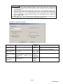
《Example for Operational settings》
Setting Item
Example for
settings
Description
Set the Parameter name.
Parameter name
Data link disorder
satation setting
Case of CPU Stop
setting
Block data
assurance per
station
“SAMPLE”
Set the input status for the data link
error station.
Set
the
slave
station
refresh/compulsory clear setting at
programmable
controller
CPU
STOP.
Set the block guarantee of cyclic
data per station.
Remarks
Even if the Parameter
name is not set, this will not affect the
operation of the CC-Link system
Clear ("Hold
input
data"
not checked)
Refresh
("Clears
compulsorily "
not checked)
Disable
("Enable
setting"
not
checked)
(12/n)
LEN080334B
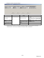
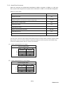
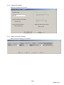
《Example for Station information settings》
Setting Item
Description
Example for
settings
Set the station data.
Station type
Number of
stations *
Remote device station
occupied
Occupies 1 station
Remote station points
32 points [when occupies 1
station]
Reserved/invalid station
select
No setting
Remarks
Set the “remote device station” in case of
the ME96.
(If setting of “Mode” is remote net(Ver.2
mode, Set the “Ver.1 Remote device
station”.)
Set the “Occupies 1 station” in case of
the ME96.
Cannot be changed.
* "Number of exclusive stations" on the screen is described as "Number of occupied stations" in this manual.
"Exclusive station 1" on the screen is described as "Occupies 1 station" in this manual
(13/n)
LEN080334B
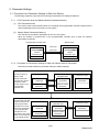
6. Communication Between the Master Station and ME96
6.1 Communication Guideline
There are three communication statuses (Initial Communication, Normal Communication, Error
Communication) between the Master station and ME96.
The following can be performed at normal communication.
・ Monitoring of the measurement values such as the current, voltage and energy, etc.
・ Monitoring of the bit data of the alarm state and the digital input state.
・ Setting the set data of the time constant for current demand.
ME96 has a special-purpose command for each measurement items and each setting items. It becomes
possible to monitor measurement value or to set the setting value by writing the command into the
remote register RWw of the master station.
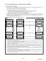
Overview of the Command Communication to ME96
Master station
Word device(Ex:W)
Remote register(RWw)
①
Bit device(Ex:Y)
Command
Command
②
Command/Data
④
Command
execution request
Automatic refresh
⑥
Remote input(RX)
Command
Command/Data
Remote output(RY)
Remote output(RY)
③
execution request
Bit device(Ex:X)
Remote register (RWw)
Link scan
Command/Data
ME96
Command
execution request
Command
execute
PLC CPU
Remote input(RX)
⑤
Command
completion reply
completion reply
completion reply
Word device(Ex:W)
Remote register(RWr)
Remote register(RWr)
Reply data to
command
①
②
③
④
⑤
⑥
⑦
⑧
⑧
Reply data to
command
⑦
Reply data to
command
By automatic refresh, command and data stored in the word device of PLC CPU are stored in the “remote
register RWw” of the master station.
By link scan, command and data stored in the “remote register RWw” of the master station are sent to ME96,
and is stored in the “remote register RWw” of the ME96.
By automatic refresh, command execution request stored in the bit device of PLC CPU is stored in the “remote
output RY” of the master station.
By link scan, command execution request stored in the “remote output RY” of the master station is sent to
ME96, and is stored in the “remote output RY” of the ME96. And then ME96 executes the command and data.
By link scan, command completion reply stored in the “remote input RX” of the ME96 is sent to the master
station, and is stored in the “remote input RX” of the master station.
By automatic refresh, command completion reply stored in the “remote input RX” of the master station is stored
in the bit device of the PLC CPU.
By link scan, reply data to command stored in the “remote register RWr” of the ME96 is sent to the master
station, and is stored in the “remote register RWr” of the master station.
By automatic refresh, reply data to command stored in the “remote register RWr” of the master station is stored
in the word device of the PLC CPU.
(14/n)
LEN080334B
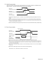
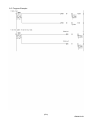
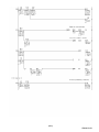
6.2 Initial Communication
Initial communication is performed at the beginning after the power supply is turned on or hardware is reset.
Refer to section 7.1 about the remote input RX and the remote output RY.
①
RX(n+1)8
(Initial data processing request flag)
③
④
②
RY(n+1)8
(Initial data setting completion flag)
③
RX(n+1)B
(Remote READY)
①After the power supply is turned on, or hardware is reset, the initial data processing request flag is turned on by
ME96.
②After the initial data processing request flag is turned on, turn on the initial data setting completion flag.
③After the initial data setting completion flag is turned on, the initial data processing request flag is turned
off and the remote READY is turned on.
④After the initial data processing request flag is turned off, turned off the initial data setting completion flag.
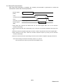
6.3 Error Communication
Error occurrence
①
RX(n+1)A
(Error status flag)
③
④
②
RY(n+1)A
(Error reset request flag)
②
Remote register
(RWr)
RX(n+1)B
Remote READY
Error code
③
①
①When an error occurs in ME96, error status flag is turned on and the remote READY is turned off.
②When the error status flag is turned on, read the error code from the remote register RWr. Eliminate the
cause of the error while referring to the red error code. When resuming communication with ME96, turn
on the error reset request flag.
③After the error reset request flag is turned on, the error status flag is turned off. Also, the remote READY
is turned on.
④After the error status flag is turned off, turn off the error reset request flag.
Note: Refer to “7.2.5 About error occurrence” for error code.
(15/n)
LEN080334B
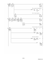
6.4 Normal Communication
After initial data processing is complete, the normally communication is performed to monitor the
measurement values and to set the parameters.
Remote register
(RWw)
Command and related data
①
④
RYnF
(Command execution request flag)
②
RXnF
(Command completion reply flag)
⑤
③
Reply data
Remote register
(RWr)
①After writing the command and related data into the remote register RWw, turn on the command
execution request flag.
②After receiving the reply data corresponding to the command, the command completion reply flag turned
on.
③After the command completion reply flag is turned on, read the reply data from the remote register RWw.
④After reading the reply data, cancel the command execution request by turning off the command
execution request flag.
⑤After the command execution request flag is turned off, the command completion reply flag is turned off.
Note: When sending commands successively, repeat ① to ⑤ above.
The command can be sent only when the remote READY is ON.
(16/n)
LEN080334B
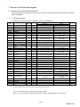
7. Remote I/O and Remote Register
7.1 Remote Input RX, Remote Output RY
The remote input RX and remote output RY are used to communicate for bit data between the master
station and ME96.
7.1.1
Remote input RX
The allocation of the remote input RX of ME96 is shown in the table below.
Device
No.
Signal name
RXn0
RXn1
RXn2
RXn3
RXn4
RXn5
Digital Input 1 (DI1)
Digital Input 2 (DI2)
Digital Input 3 (DI3)
Digital Input 4 (DI4)
Reserved
Alarm (Total)
Alarm
of
Current
RXn6
Demand
Alarm of
RXn7
Active power Demand
RXn8
Alarm of Voltage
RXn9
Alarm of Current
RXnA
Alarm of Active power
Alarm of Reactive
RXnB
power
RXnC
Alarm of Frequency
RXnD
Alarm of Power factor
Alarm
of
T.H.D
RXnE
(Voltage)
Command completion
RXnF
reply flag
RX(n+1)0 Reserved
RX(n+1)1 Reserved
RX(n+1)2 Reserved
RX(n+1)3 Reserved
RX(n+1)4 Reserved
RX(n+1)5 Reserved
RX(n+1)6 Reserved
RX(n+1)7 Reserved
Initial data processing
RX(n+1)8
request flag
RX(n+1)9 Reserved
RX(n+1)A Error status flag
Description
ME96NSR
ME96SSH
ME96SSR
○
○
○
○
○
○
OFF(0)
OFF
OFF
OFF
OFF
Note
ON(1)
ON
ON
ON
ON
○
○
-
-
-
-
○
○
Non-Alarm state
Alarm state
○
○
Non-Alarm state
Alarm state
-
○
Non-Alarm state
Alarm state
○
○
○
○
○
○
Non-Alarm state
Non-Alarm state
Non-Alarm state
Alarm state
Alarm state
Alarm state
○
○
Non-Alarm state
Alarm state
○
○
○
○
Non-Alarm state
Non-Alarm state
Alarm state
Alarm state
○
○
Non-Alarm state
Alarm state
○
○
No receiving of reply date
Receiving of reply data
-
-
-
-
-
-
-
-
-
-
-
-
-
-
-
-
-
-
-
-
-
-
-
-
-
-
-
-
-
-
-
-
○
○
Power OFF, remote READY
ON, or error status flag ON
Power supply is turned ON
or hardware reset
-
○
-
○
RX(n+1)B Remote READY
○
○
Command sending not
possible
RX(n+1)C
RX(n+1)D
RX(n+1)E
RX(n+1)F
-
-
-
-
-
-
-
-
-
-
-
-
-
-
-
-
Reserved
Reserved
Reserved
Reserved
-
-
No error occurrence
Error occurrence
Normally communication
status (Command sending
possible)
*1, *2
*1
*1
*1
*1: For the details, refer to “6.Communication Between the Master Station and ME”
*2: Alarm of harmonic current cannot be shown by remote input RX.
Note 1: RX is bit data which is stored the input status of ME96.
Note 2: The “n” in the table is determined by the station number of ME96. (Refer to the next page)
(17/n)
LEN080334B
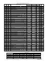
(1)
1)
Relationships between programmable controller CPU, master module and ME96(RX)
1) The input status of ME96 is stored automatically (for each link scan) in the master station's
"remote input RX" buffer memory.
2) The input status stored in the "remote input RX" buffer memory is stored in the CPU device set
with the automatic refresh parameters.
Programmable controller CPU
Master module
X100~X10F
X110~X11F
X120~X12F
X130~X13F
X140~X14F
X150~X15F
Remote input(RX)
Remote input(RX)
Device X
ME96
(Station number1)
ME96
(Station number2)
ME96
(Station number3)
ME96tation number 1)
2)
2)
2)
RX00~RX0F
RX10~RX1F
RX20~RX2F
RX30~RX3F
RX40~RX4F
RX50~RX5F
1)
RX00~RX0F
RX10~RX1F
1)
1)
ME96(Station number 2)
Remote input(RX)
RX00~RX0F
RX10~RX1F
to
to
ME96(Station number 3)
ME96
X620~X62F
(Station number42) X630~X63F
2)
RX520~RX52F
RX530~RX53F
1)
Remote input(RX)
RX00~RX0F
RX10~RX1F
to
ME96(Station number 42)
Remote input(RX)
RX00~RX0F
RX10~RX1F
Station
Station
Station
Device No.
Device No.
Device No.
number
number
number
1
X100
to X11F
15
X2C0
to X2D9
29
X480
to X49F
2
X120
to X13F
16
X2E0
to X2F9
30
X4A0
to X4B9
3
X140
to X15F
17
X300
to X31F
31
X4C0
to X4D9
4
X160
to X17F
18
X320
to X33F
32
X4E0
to X4F9
5
X180
to X19F
19
X340
to X35F
33
X500
to X51F
6
X1A0
to X1B9
20
X360
to X37F
34
X520
to X53F
7
X1C0
to X1D9
21
X380
to X39F
35
X540
to X55F
8
X1E0
to X1F9
22
X3A0
to X3B9
36
X560
to X57F
9
X200
to X21F
23
X3C0
to X3D9
37
X580
to X59F
10
X220
to X23F
24
X3E0
to X3F9
38
X5A0
to X5B9
11
X240
to X25F
25
X400
to X41F
39
X5C0
to X5D9
12
X260
to X27F
26
X420
to X43F
40
X5E0
to X5F9
13
X280
to X29F
27
X440
to X45F
41
X600
to X61F
14
X2A0
to X2B9
28
X460
to X47F
42
X620
to X63F
Device No. is determined to “X100 to X63F” if refresh device of remote input (RX) is set to “X100”.
(18/n)
LEN080334B
7.1.2
Remote Output RY
The allocation of the remote output RY of ME96 is shown in the table below.
Device
No.
Signal name
Description
ON(1)→OFF(0)
OFF(0)→ON(1)
RYn0
Reserved
-
-
RYn1
Reserved
-
-
-
RYn2
Reserved
-
RYn3
Reserved
-
-
RYn4
Reserved
-
-
RYn5
Reserved
-
-
RYn6
Reserved
-
-
RYn7
Reserved
-
-
RYn8
Reserved
-
-
RYn9
Reserved
-
-
-
RYnA
Reserved
-
RYnB
Reserved
-
-
RYnC
Reserved
-
-
RYnD
Reserved
-
-
RYnE
Reserved
-
-
Cancel command request
Command request
RYnF
Command execution
request flag
RY(n+1)0
Reserved
-
-
RY(n+1)1
Reserved
-
-
-
RY(n+1)2
Reserved
-
RY(n+1)3
Reserved
-
-
RY(n+1)4
Reserved
-
-
RY(n+1)5
Reserved
-
-
RY(n+1)6
Reserved
-
-
RY(n+1)7
Reserved
-
-
Initial data
Cancel normal communication
request
Normal communication
request
RY(n+1)8
RY(n+1)9
RY(n+1)A
setting completion flag
Reserved
Error reset request flag
-
-
Cancel error reset request
Error reset request
-
RY(n+1)B
Reserved
-
RY(n+1)C
Reserved
-
-
RY(n+1)D
Reserved
-
-
RY(n+1)E
Reserved
-
-
RY(n+1)F
Reserved
-
-
Note
*1
*1
*1
*1: For the details, refet to “6.Communication Between the Master Station and ME”
Note 1: The “n” in the table is determined by the station number of ME96. (Refer to the next page)
Point
Do not read or write to reserved remote registers. If reading or writing is performed, the
functions of ME96 are not guaranteed.
(19/n)
LEN080334B
(1)
1)
Relationships between programmable controller CPU, master module and ME96(RY)
1) The on/off data of the CPU device set with the automatic refresh parameters is stored in the
"remote output RY" buffer memory.
2) Remote output RY is automatically set to on/off (for each link scan) according to the output status
stored in the "remote output RY" buffer memory.
Programmable controller CPU
ME96
(Station number1)
ME96
(Station number2)
ME96
(Station number3)
Device Y
Y100~Y10F
Y110~Y11F
Y120~Y12F
Y130~Y13F
Y140~Y14F
Y150~Y15F
Master module
ME96(Station number 1)
Remote output(RY)
1)
1)
1)
2)
RY00~RY0F
RY10~RY1F
RY20~RY2F
RY30~RY3F
RY40~RY4F
RY50~RY5F
Remote output(RY)
RY00~RY0F
RY10~RY1F
2)
2)
ME96(Station number 2)
Remote output(RY)
RY00~RY0F
RY10~RY1F
to
to
ME96(Station number 3)
ME96
Y620~Y62F
(Station number42) Y630~Y63F
1)
Remote output(RY)
RY00~RY0F
RY10~RY1F
2)
RY520~RY52F
RY530~RY53F
to
ME96(Station number 42)
Remote output(RY)
RY00~RY0F
RY10~RY1F
Station
Station
Device No.
number
number
1
Y100
to Y11F
15
2
Y120
to Y13F
16
3
Y140
to Y15F
17
4
Y160
to Y17F
18
5
Y180
to Y19F
19
6
Y1A0
to Y1B9
20
7
Y1C0
to Y1D9
21
8
Y1E0
to Y1F9
22
9
Y200
to Y21F
23
10
Y220
to Y23F
24
11
Y240
to Y25F
25
12
Y260
to Y27F
26
13
Y280
to Y29F
27
14
Y2A0
to Y2B9
28
Device No. is determined to “Y100 to Y63F” if
Device No.
Y2C0
Y2E0
Y300
Y320
Y340
Y360
Y380
Y3A0
Y3C0
Y3E0
Y400
Y420
Y440
Y460
to
to
to
to
to
to
to
to
to
to
to
to
to
to
Y2D9
Y2F9
Y31F
Y33F
Y35F
Y37F
Y39F
Y3B9
Y3D9
Y3F9
Y41F
Y43F
Y45F
Y47F
Station
number
29
30
31
32
33
34
35
36
37
38
39
40
41
42
Device No.
Y480
Y4A0
Y4C0
Y4E0
Y500
Y520
Y540
Y560
Y580
Y5A0
Y5C0
Y5E0
Y600
Y620
to
to
to
to
to
to
to
to
to
to
to
to
to
to
Y49F
Y4B9
Y4D9
Y4F9
Y51F
Y53F
Y55F
Y57F
Y59F
Y5B9
Y5D9
Y5F9
Y61F
Y63F
refresh device of remote output (RY) is set to “Y100”.
(20/n)
LEN080334B
7.2 Remote Register (RWr, RWw)
The remote register RWr and RWw are used to communicate word data between the master station and
ME96. Because it occupiers 1 station, the remote registers RWr and RWw each have 4 words in length.
ME96 has the special-purpose commands for each measurement items and setting items.It becomes
possible to monitor each measurement values or set each parameters by writing into the remote register
RWw of the master station command and the related data allocated to the item you want to monitor or set.
(21/n)
LEN080334B
(1)
1)
Relationships between programmable controller CPU, master module and ME96(RWr)
1) The remote register RWr data of a remote device station is automatically stored in the "remote
register Rwr" buffer memory of the master station.
2) The remote register RWr data of ME96 stored in the "remote register RWr" buffer memory is
stored in the CPU device set with the automatic refresh parameters.
Programmable controller CPU
Master module
ME96
(Station number1)
ME96
(Station number2)
2)
2)
RWr0
RWr1
RWr2
RWr3
RWr4
RWr5
RWr6
RWr7
to
ME96
(Station number42)
W3A4
W3A5
W3A6
W3A7
Remote register(RWr)
Remote register(RWr)
Device No.
W300
W301
W302
W303
W304
W305
W306
W307
ME96(Station number 1)
1)
1)
RWrA4
RWrA5
RWrA6
RWrA7
ME96(Station number 2)
Remote register(RWr)
RWr0
RWr1
RWr2
RWr3
to
2)
RWr0
RWr1
RWr2
RWr3
1)
to
ME96(Station number 42)
Remote register(RWr)
RWr0
RWr1
RWr2
RWr3
Station
Station
Station
Device No.
Device No.
Device No.
number
number
number
1
W300 to W303 15
W338 to W33B 29
W370 to W373
2
W304 to W307 16
W33C to W33F 30
W374 to W377
3
W308 to W30B 17
W340 to W343 31
W378 to W37B
4
W30C to W30F 18
W344 to W347 32
W37C to W37F
5
W310 to W313 19
W348 to W34B 33
W380 to W383
6
W314 to W317 20
W34C to W34F 34
W384 to W387
7
W318 to W31B 21
W350 to W353 35
W388 to W38B
8
W31C to W31F 22
W354 to W357 36
W38C to W38F
9
W320 to W323 23
W358 to W35B 37
W390 to W393
10
W324 to W327 24
W35C to W35F 38
W394 to W397
11
W328 to W32B 25
W360 to W363 39
W398 to W39B
12
W32C to W32F 26
W364 to W367 40
W39C to W39F
13
W330 to W333 27
W368 to W36B 41
W3A0 to W3A3
14
W334 to W337 28
W36C to W36F 42
W3A4 to W3A7
Device No. is determined to “W300 to W3A7” if refresh device of remote register (RWr) is set to “W300”.
(22/n)
LEN080334B
(2)
2)
Relationships between programmable controller CPU, master module and ME96(RWw)
1) The transmission data of the CPU device set with the automatic refresh parameters is stored in the
"remote register RWw" buffer memory.
2) The data stored in the "remote register RWw" buffer memory is automatically sent to the remote
register RWw of each remote device station.
Programmable controller CPU
Master module
ME96
(Station number1)
ME96
(Station number2)
1)
1)
RWw0
RWw1
RWw2
RWw3
RWw4
RWw5
RWw6
RWw7
to
ME96
(Station number42)
W4A4
W4A5
W4A6
W4A7
Remote register(RWw)
Remote register(RWw)
Device No.
W400
W401
W402
W403
W404
W405
W406
W407
ME96(Station number 1)
2)
2)
RWwA4
RWwA5
RWwA6
RWwA7
ME96(Station number 2)
Remote register(RWw)
RWw0
RWw1
RWw2
RWw3
to
1)
RWw0
RWw1
RWw2
RWw3
2)
to
ME96(Station number 42)
Remote register(RWw)
RWw0
RWw1
RWw2
RWw3
Station
Station
Station
Device No.
Device No.
Device No.
number
number
number
1
W400 to W403 15
W438 to W43B 29
W470 to W473
2
W404 to W407 16
W43C to W43F 30
W474 to W477
3
W408 to W40B 17
W440 to W443 31
W478 to W47B
4
W40C to W40F 18
W444 to W447 32
W47C to W47F
5
W410 to W413 19
W448 to W44B 33
W480 to W483
6
W414 to W417 20
W44C to W44F 34
W484 to W487
7
W418 to W41B 21
W450 to W453 35
W488 to W48B
8
W41C to W41F 22
W454 to W457 36
W48C to W48F
9
W420 to W423 23
W458 to W45B 37
W490 to W493
10
W424 to W427 24
W45C to W45F 38
W494 to W497
11
W428 to W42B 25
W460 to W463 39
W498 to W49B
12
W42C to W42F 26
W464 to W467 40
W49C to W49F
13
W430 to W433 27
W468 to W46B 41
W4A0 to W4A3
14
W434 to W437 28
W46C to W46F 42
W4A4 to W4A7
Device No. is determined to “W400 to W4A7” if refresh device of remote register (RWw) is set to “W400”.
(23/n)
LEN080334B
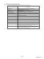
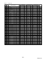
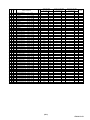
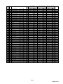
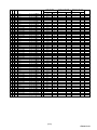
7.2.1
Supported Commands
The commands supported by ME96 are listed in the table below. For the details of each commands, refer to
“7.2.2 Details of Commands“.
Table 7.1 Suppoted Commands
Command
Name
Descriprion
Note
page
1H
Data Monitor
For monitoring measurement
25
2H
Data Set
For setting measurement
37
Note) 1: The command can be sent only when the remote READY is ON.
2: The command execution request flag and command completion reply flag are used to send the
command and receive replay data. For details of each flag, refer to “6.4 Normal Communication”.
3: In case of monitoring the present value and its maximum continuously according to the renewal data
timing of ME96, the maximum may be smaller than the present value.
(24/n)
LEN080334B
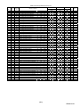
7.2.2
Details of Commands
The details of the command and reply data supported by ME96 are described here.
(1)
Data Monitor Command (1H)
1H
Data Monitor
・ The measurement items are assigned “Unit No.”, ”Group No.” and “Channel No.”. (Refer to Table 7.2 to Table
7.12.)
・ After writing the command as shown below into the remote register RWw, set the command excution request
flag to ON(1). When the command completion reply frag is turned on, the item specified is reset.
・ The details of the data format are shown in the section 7.2.3.
・ The monitering item is changed with the setting of phase wire system. (Refer to Table 7.2 to Table 7.12.)
Remote register RWw (Programmable controller→ME96) Remote register RWr (ME96→Programmable controller)
b15
m
b8
Group No.
b7
b4
Unit No.
b3
b0
1H
(Command)
b15
b8
b7
b0
n
Channel No.
Group No.
Index number
00H
m+1
00H
Channel No.
n+1
m+2
00H
00H
n+2
Low data
m+3
00H
00H
n+3
High data
(※)0H and 1H is used in the unit No. of ME96
m, n : Address is allocated to the master module by the station number setting.
Note: ME96 can monitor the value of the measurement items which are not displayed.
*1: It is described as 8 bits data by combining the unit No. (high 4 bits) and the command (low 4 bits).
b7
b4 b3
b0
Command: data range ・・・ 0H~7H
Unit No.: data range ・・・ 0H~7H
0H and 1H are used in ME96
For example, When the unit No. is 0H and the command is 1H, it becomes “01H”.
(25/n)
LEN080334B
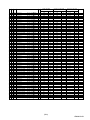
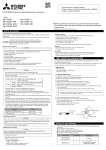
Table 7.2 Group Channel List (1/11)
Unit
No.
0
0
0
0
0
0
0
0
0
0
0
0
0
0
0
0
0
0
0
0
0
0
0
0
0
0
0
0
0
0
0
0
0
0
0
0
0
0
0
0
0
0
0
0
0
0
0
0
0
0
0
0
0
0
0
0
Group Channel
(h)
(h)
F0
E0
E0
E0
E0
E0
E0
E0
E0
E0
E0
02
08
08
01
01
01
01
01
01
01
01
01
01
01
01
01
01
01
02
02
02
02
02
02
02
02
02
02
02
02
02
02
02
05
05
05
05
05
05
05
05
05
05
05
05
02
11
12
1B
1C
13
1D
1E
18
19
1A
E0
E4
E5
01
21
41
61
81
02
22
42
62
82
05
25
45
65
85
01
21
41
61
81
02
22
42
62
82
05
25
45
65
85
01
21
41
61
02
22
42
62
05
25
45
65
ME96SSH-MB
Name of Cannel
Model code
Primary current
Primary voltage(L-L)
Primary voltage(L-N)
Secondary voltage(L-N)
Phase & Wiring
Frequency
Secondary current
Alarm items
Byte monitor
Attribute monitor
Time constant for current demand
Interval time constant
Subinterval time constant
Average current
Phase 1 current
Phase 2 current
Phase 3 current
Phase N current
Average current
Phase 1 current
Phase 2 current
Phase 3 current
Phase N current
Average current
Phase 1 current
Phase 2 current
Phase 3 current
Phase N current
Average current demand
Phase 1 current demand
Phase 2 current demand
Phase 3 current demand
Phase N current demand
Average current demand
Phase 1 current demand
Phase 2 current demand
Phase 3 current demand
Phase N current demand
Average current demand
Phase 1 current demand
Phase 2 current demand
Phase 3 current demand
Phase N current demand
Average L-L voltage
1-2 voltage
2-3 voltage
3-1 voltage
Average L-L voltage
1-2 voltage
2-3 voltage
3-1 voltage
Average L-L voltage
1-2 voltage
2-3 voltage
3-1 voltage
ME96SSR-MB
ME96NSR Data
Note
type
3P3W
3P3W
3P4W
1P2W 3P4W
1P2W 3P4W 3P3W
1P3W
1P3W
sec.
min.
min.
A
A
A
A
A
A
A
A
A
A
A
A
A
A
A
A
A
A
A
A
A
A
A
A
A
A
A
A
A
A
V
V
V
V
V
V
V
V
V
V
V
V
Inst.
Inst.
Inst.
Inst.
Inst.
max.
max.
max.
max.
max.
min.
min.
min.
min.
min.
Inst.
Inst.
Inst.
Inst.
Inst.
max.
max.
max.
max.
max.
min.
min.
min.
min.
min.
Inst.
Inst.
Inst.
Inst.
max.
max.
max.
max.
min.
min.
min.
min.
○
○
○
○
○
○
○
○
○
○
○
○
○
○
○
○
○
○
○
○
○
○
○
○
○
○
○
○
○
○
○
○
○
○
○
○
○
○
○
○
○
○
○
○
○
○
○
○
○
○
○
○
○
○
○
○
○
○
○
○
○
○
○
○
○
○
○
○
○
○
○
○
○
○
○
○
○
○
○
○
○
○
○
○
○
○
○
○
○
○
○
○
○
○
○
○
○
○
○
○
○
○
○
○
○
○
○
○
○
○
○
○
○
○
○
○
○
○
○
○
○
○
○
○
○
○
○
-
○
○
○
○
○
○
○
○
○
○
○
○
○
○
○
○
○
○
○
○
○
○
○
○
○
○
○
○
○
○
○
○
○
○
○
○
○
○
○
○
○
○
○
○
○
○
○
○
○
○
○
○
○
○
○
○
○
○
○
○
○
○
○
○
○
○
○
○
○
○
○
○
○
○
○
○
○
○
○
○
○
○
○
○
○
○
○
○
○
○
○
○
○
○
○
○
○
○
○
○
○
○
○
○
○
○
○
○
○
○
○
○
○
○
○
○
○
○
○
○
○
-
○
○
○
○
○
○
○
○
○
○
○
○
○
○
○
○
○
○
○
○
○
○
○
○
○
○
○
○
○
○
○
○
○
○
○
○
○
○
○
○
○
○
○
○
○
○
○
○
○
○
○
○
○
○
○
○
○
○
○
○
○
○
○
○
○
○
○
○
○
○
○
○
○
○
○
○
○
○
○
○
○
○
○
○
○
○
○
○
○
○
○
○
○
○
○
○
○
⑥
⑤
⑤
⑤
⑤
⑥
⑤
⑤
⑦
⑥
⑥
⑥
⑥
⑥
①
①
①
①
①
①
①
①
①
①
①
①
①
①
①
①
①
①
①
①
①
①
①
①
①
①
①
①
①
①
①
①
①
①
①
①
①
①
①
①
①
①
*2,*3
Note: Measurement data correspond as follows according to setting of phase wiring. (Maximum / Minimum data and harmonic data are same.)
Name of channel
1-2 voltage
2-3 voltage
3-1 voltage
Phase 1 current
Phase 2 current
Phase 3 current
3P3W
1-2 voltage
2-3 voltage
3-1 voltage
Phase 1 current
Phase 2 current
Phase 3 current
Phase wiring
1P3W(1N3)
1P3W(1N2)
1-N voltage
1-N voltage
3-N voltage
2-N voltage
1-3 voltage
1-3 voltage
Phase 1 current
Phase 1 current
Phase N current
Phase N current
Phase 3 current
Phase 2 current
(26/n)
1P2W
Voltage
Current
-
LEN080334B
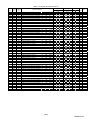
Table 7.3 Group Channel List (2/11)
Unit
No.
0
0
0
0
0
0
0
0
0
0
0
0
0
0
0
0
0
0
0
0
0
0
0
0
0
0
0
0
0
0
0
0
0
0
0
0
0
0
1
1
1
1
1
1
1
1
1
1
1
1
Group Channel
(h)
(h)
03
03
03
03
03
03
03
03
03
03
03
03
07
07
07
07
07
07
07
07
07
07
07
07
08
08
09
09
09
09
09
09
09
09
09
09
09
09
0B
0B
0B
0B
0B
0B
0B
0B
0B
0B
0B
0B
01
21
41
61
02
22
42
62
05
25
45
65
01
21
41
61
02
22
42
62
05
25
45
65
01
02
01
21
41
61
02
22
42
62
05
25
45
65
01
21
41
61
02
22
42
62
05
25
45
65
ME96SSH-MB
Name of Cannel
Average L-N voltage
1-N voltage
2-N voltage
3-N voltage
Average L-N voltage
1-N voltage
2-N voltage
3-N voltage
Average L-N voltage
1-N voltage
2-N voltage
3-N voltage
Total active power
Phase 1 active power
Phase 2 active power
Phase 3 active power
Total active power
Phase 1 active power
Phase 2 active power
Phase 3 active power
Total active power
Phase 1 active power
Phase 2 active power
Phase 3 active power
Total rolling demand
Total rolling demand
Total reactive power
Phase 1 reactive power
Phase 2 reactive power
Phase 3 reactive power
Total reactive power
Phase 1 reactive power
Phase 2 reactive power
Phase 3 reactive power
Total reactive power
Phase 1 reactive power
Phase 2 reactive power
Phase 3 reactive power
Total apparent power
Phase 1 apparent power
Phase 2 apparent power
Phase 3 apparent power
Total apparent power
Phase 1 apparent power
Phase 2 apparent power
Phase 3 apparent power
Total apparent power
Phase 1 apparent power
Phase 2 apparent power
Phase 3 apparent power
ME96SSR-MB
ME96NSR Data
Note
type
3P3W
3P3W
3P4W
1P2W 3P4W
1P2W 3P4W 3P3W
1P3W
1P3W
V
V
V
V
V
V
V
V
V
V
V
V
kW
kW
kW
kW
kW
kW
kW
kW
kW
kW
kW
kW
kW
kW
kvar
kvar
kvar
kvar
kvar
kvar
kvar
kvar
kvar
kvar
kvar
kvar
kVA
kVA
kVA
kVA
kVA
kVA
kVA
kVA
kVA
kVA
kVA
kVA
Inst.
Inst.
Inst.
Inst.
max.
max.
max.
max.
min.
min.
min.
min.
Inst.
Inst.
Inst.
Inst.
max.
max.
max.
max.
min.
min.
min.
min.
Inst.
max.
Inst.
Inst.
Inst.
Inst.
max.
max.
max.
max.
min.
min.
min.
min.
Inst.
Inst.
Inst.
Inst.
max.
max.
max.
max.
min.
min.
min.
min.
○
○
○
○
○
○
○
○
○
○
○
○
○
○
○
○
○
○
○
○
○
○
○
○
○
○
○
○
○
○
○
○
○
○
○
○
○
○
○
○
○
○
○
○
○
○
○
○
○
○
○
○
○
○
○
○
○
○
-
○
○
○
○
○
○
○
○
-
○
○
○
○
○
○
○
○
○
○
○
○
○
○
○
○
○
○
○
○
○
○
○
○
○
○
○
○
○
○
○
○
○
○
○
○
○
○
○
○
○
○
○
○
○
○
○
○
○
○
○
○
○
○
-
○
○
○
○
○
○
-
○
○
○
○
○
○
○
○
○
○
○
○
○
○
○
○
○
○
○
○
○
○
○
○
○
○
○
○
○
○
○
○
○
○
○
○
○
○
○
○
○
○
○
○
○
○
○
○
○
○
○
○
○
○
-
①
①
①
①
①
①
①
①
①
①
①
①
①
①
①
①
①
①
①
①
①
①
①
①
①
①
①
①
①
①
①
①
①
①
①
①
①
①
①
①
①
①
①
①
①
①
①
①
①
①
(27/n)
LEN080334B
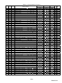
Table 7.4 Group Channel List (3/11)
Unit
No.
0
0
0
0
0
0
0
0
0
0
0
0
0
0
0
0
0
0
0
0
0
0
0
1
1
1
1
1
1
1
1
1
0
0
0
0
0
0
0
1
1
1
1
1
1
1
1
1
Group Channel
(h)
(h)
0D
0D
0D
0D
0D
0D
0D
0D
0D
0D
0D
0D
0F
0F
0F
63
4D
4F
51
53
55
57
59
5B
5D
5F
61
79
79
79
79
79
76
76
76
76
76
76
76
76
76
76
76
79
79
79
79
79
01
21
41
61
02
22
42
62
05
25
45
65
01
02
05
21
21
21
21
21
21
21
21
21
21
21
21
02
04
06
08
0A
86
73
75
77
79
7B
7D
7F
81
83
85
72
74
76
78
7A
ME96SSH-MB
Name of Cannel
Total power factor
Phase 1 power factor
Phase 2 power factor
Phase 3 power factor
Total power factor
Phase 1 power factor
Phase 2 power factor
Phase 3 power factor
Total power factor
Phase 1 power factor
Phase 2 power factor
Phase 3 power factor
Frequency
Frequency
Frequency
1-2 harmonic voltage
1-2 harmonic voltage
1-2 harmonic voltage
1-2 harmonic voltage
1-2 harmonic voltage
1-2 harmonic voltage
1-2 harmonic voltage
1-2 harmonic voltage
1-2 harmonic voltage
1-2 harmonic voltage
1-2 harmonic voltage
1-2 harmonic voltage
1-2 harmonic voltage
1-2 harmonic voltage
1-2 harmonic voltage
1-2 harmonic voltage
1-2 harmonic voltage
1-2 voltage THD
1-2 voltage harmonic distortion
1-2 voltage harmonic distortion
1-2 voltage harmonic distortion
1-2 voltage harmonic distortion
1-2 voltage harmonic distortion
1-2 voltage harmonic distortion
1-2 voltage harmonic distortion
1-2 voltage harmonic distortion
1-2 voltage harmonic distortion
1-2 voltage harmonic distortion
1-2 voltage harmonic distortion
1-2 voltage harmonic distortion
1-2 voltage harmonic distortion
1-2 voltage harmonic distortion
1-2 voltage harmonic distortion
ME96SSR-MB
ME96NSR Data
Note
type
3P3W
3P3W
3P4W
1P2W 3P4W
1P2W 3P4W 3P3W
1P3W
1P3W
%
%
%
%
%
%
%
%
%
%
%
%
Hz
Hz
Hz
V
V
V
V
V
V
V
V
V
V
V
V
V
V
V
V
V
%
%
%
%
%
%
%
%
%
%
%
%
%
%
%
%
Inst.
Inst.
Inst.
Inst.
max.
max.
max.
max.
min.
min.
min.
min.
Inst.
max.
min.
Inst.
Inst.
Inst.
Inst.
Inst.
Inst.
Inst.
Inst.
Inst.
Inst.
Inst.
Inst.
Inst.
Inst.
Inst.
Inst.
Inst.
Inst.
Inst.
Inst.
Inst.
Inst.
Inst.
Inst.
Inst.
Inst.
Inst.
Inst.
Inst.
Inst.
Inst.
Inst.
Inst.
Total
1st
3rd
5th
7th
9th
11th
13th
15th
17th
19th
21st
23rd
25th
27th
29th
31st
Total
3rd
5th
7th
9th
11th
13th
15th
17th
19th
21st
23rd
25th
27th
29th
31st
○
○
○
○
○
○
○
○
○
○
○
○
○
○
○
-
○
○
○
○
○
○
○
○
○
○
○
○
○
○
○
○
○
○
○
○
○
○
○
○
○
○
○
○
○
○
○
○
○
○
○
○
○
○
○
○
○
○
○
○
○
○
○
○
○
○
○
○
○
○
○
○
○
○
○
○
○
○
○
○
○
○
○
○
○
○
○
○
○
○
○
○
○
○
○
○
○
○
○
○
○
○
○
○
○
○
○
○
○
-
○
○
○
○
○
○
○
○
○
○
○
○
○
○
○
○
○
○
○
○
○
-
○
○
○
○
○
○
○
○
○
○
○
○
○
○
○
○
○
○
○
○
○
-
○
○
○
○
○
○
○
○
○
○
○
○
○
○
○
-
○
○
○
○
○
○
○
○
○
○
○
○
○
○
○
○
○
○
○
○
○
-
①
①
①
①
①
①
①
①
①
①
①
①
①
①
①
①
①
①
①
①
①
①
①
①
①
①
①
①
①
①
①
①
①
①
①
①
①
①
①
①
①
①
①
①
①
①
①
①
(28/n)
LEN080334B
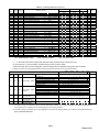
Table 7.5 Group Channel List (4/11)
Unit
No.
0
0
0
0
0
0
0
0
1
1
1
1
1
1
1
1
1
0
0
0
0
0
0
0
1
1
1
1
1
1
1
1
1
0
0
0
0
0
0
0
0
1
1
1
1
1
1
1
1
1
Group Channel
(h)
(h)
63
4D
4F
51
53
55
57
59
5B
5D
5F
61
79
79
79
79
79
76
76
76
76
76
76
76
76
76
76
76
79
79
79
79
79
76
4D
76
76
76
76
76
76
76
76
76
76
79
79
79
79
79
41
41
41
41
41
41
41
41
41
41
41
41
18
1A
1C
1E
20
9C
89
8B
8D
8F
91
93
95
97
99
9B
88
8A
8C
8E
90
DE
A2
CB
CD
CF
D1
D3
D5
D7
D9
DB
DD
CA
CC
CE
D0
D2
ME96SSH-MB
Name of Cannel
2-3 harmonic voltage
2-3 harmonic voltage
2-3 harmonic voltage
2-3 harmonic voltage
2-3 harmonic voltage
2-3 harmonic voltage
2-3 harmonic voltage
2-3 harmonic voltage
2-3 harmonic voltage
2-3 harmonic voltage
2-3 harmonic voltage
2-3 harmonic voltage
2-3 harmonic voltage
2-3 harmonic voltage
2-3 harmonic voltage
2-3 harmonic voltage
2-3 harmonic voltage
2-3 voltage THD
2-3 voltage harmonic distortion
2-3 voltage harmonic distortion
2-3 voltage harmonic distortion
2-3 voltage harmonic distortion
2-3 voltage harmonic distortion
2-3 voltage harmonic distortion
2-3 voltage harmonic distortion
2-3 voltage harmonic distortion
2-3 voltage harmonic distortion
2-3 voltage harmonic distortion
2-3 voltage harmonic distortion
2-3 voltage harmonic distortion
2-3 voltage harmonic distortion
2-3 voltage harmonic distortion
2-3 voltage harmonic distortion
L-L voltage THD
L-L harmonic voltage
L-L voltage harmonic distortion
L-L voltage harmonic distortion
L-L voltage harmonic distortion
L-L voltage harmonic distortion
L-L voltage harmonic distortion
L-L voltage harmonic distortion
L-L voltage harmonic distortion
L-L voltage harmonic distortion
L-L voltage harmonic distortion
L-L voltage harmonic distortion
L-L voltage harmonic distortion
L-L voltage harmonic distortion
L-L voltage harmonic distortion
L-L voltage harmonic distortion
L-L voltage harmonic distortion
ME96SSR-MB
ME96NSR Data
Note
type
3P3W
3P3W
3P4W
1P2W 3P4W
1P2W 3P4W 3P3W
1P3W
1P3W
V
V
V
V
V
V
V
V
V
V
V
V
V
V
V
V
V
%
%
%
%
%
%
%
%
%
%
%
%
%
%
%
%
%
V
%
%
%
%
%
%
%
%
%
%
%
%
%
%
%
Inst.
Inst.
Inst.
Inst.
Inst.
Inst.
Inst.
Inst.
Inst.
Inst.
Inst.
Inst.
Inst.
Inst.
Inst.
Inst.
Inst.
Inst.
Inst.
Inst.
Inst.
Inst.
Inst.
Inst.
Inst.
Inst.
Inst.
Inst.
Inst.
Inst.
Inst.
Inst.
Inst.
max.
max.
max.
max.
max.
max.
max.
max.
max.
max.
max.
max.
max.
max.
max.
max.
max.
Total
1st
3rd
5th
7th
9th
11th
13th
15th
17th
19th
21st
23rd
25th
27th
29th
31st
Total
3rd
5th
7th
9th
11th
13th
15th
17th
19th
21st
23rd
25th
27th
29th
31st
Total
1st
3rd
5th
7th
9th
11th
13th
15th
17th
19th
21st
23rd
25th
27th
29th
31st
-
○
○
○
○
○
○
○
○
○
○
○
○
○
○
○
○
○
○
○
○
○
○
○
○
○
○
○
○
○
○
○
○
○
○
○
○
○
○
○
○
○
○
○
○
○
○
○
○
○
○
○
○
○
○
○
○
○
○
○
○
○
○
○
○
○
○
○
-
○
○
○
○
○
○
○
○
○
○
○
○
○
○
○
○
○
○
○
○
○
○
○
-
○
○
○
○
○
○
○
○
-
-
○
○
○
○
○
○
○
○
○
○
○
○
○
○
○
○
○
○
○
○
○
○
○
-
①
①
①
①
①
①
①
①
①
①
①
①
①
①
①
①
①
①
①
①
①
①
①
①
①
①
①
①
①
①
①
①
①
①
①
①
①
①
①
①
①
①
①
①
①
①
①
①
①
①
(29/n)
LEN080334B
Table 7.6 Group Channel List (5/11)
Unit
No.
0
0
1
1
1
1
1
1
1
1
1
1
1
1
1
1
1
0
0
0
0
0
0
0
1
1
1
1
1
1
1
1
1
0
0
1
1
1
1
1
1
1
1
1
1
1
1
1
1
1
Group Channel
(h)
(h)
4B
35
37
39
3B
3D
3F
41
43
45
47
49
7A
7A
7A
7A
7A
77
77
77
77
77
77
77
77
77
77
77
7A
7A
7A
7A
7A
4B
35
37
39
3B
3D
3F
41
43
45
47
49
7A
7A
7A
7A
7A
21
21
21
21
21
21
21
21
21
21
21
21
02
04
06
08
0A
86
73
75
77
79
7B
7D
7F
81
83
85
72
74
76
78
7A
41
41
41
41
41
41
41
41
41
41
41
41
18
1A
1C
1E
20
ME96SSH-MB
Name of Cannel
1-N harmonic voltage
1-N harmonic voltage
1-N harmonic voltage
1-N harmonic voltage
1-N harmonic voltage
1-N harmonic voltage
1-N harmonic voltage
1-N harmonic voltage
1-N harmonic voltage
1-N harmonic voltage
1-N harmonic voltage
1-N harmonic voltage
1-N harmonic voltage
1-N harmonic voltage
1-N harmonic voltage
1-N harmonic voltage
1-N harmonic voltage
1-N voltage THD
1-N voltage harmonic distortion
1-N voltage harmonic distortion
1-N voltage harmonic distortion
1-N voltage harmonic distortion
1-N voltage harmonic distortion
1-N voltage harmonic distortion
1-N voltage harmonic distortion
1-N voltage harmonic distortion
1-N voltage harmonic distortion
1-N voltage harmonic distortion
1-N voltage harmonic distortion
1-N voltage harmonic distortion
1-N voltage harmonic distortion
1-N voltage harmonic distortion
1-N voltage harmonic distortion
2-N harmonic voltage
2-N harmonic voltage
2-N harmonic voltage
2-N harmonic voltage
2-N harmonic voltage
2-N harmonic voltage
2-N harmonic voltage
2-N harmonic voltage
2-N harmonic voltage
2-N harmonic voltage
2-N harmonic voltage
2-N harmonic voltage
2-N harmonic voltage
2-N harmonic voltage
2-N harmonic voltage
2-N harmonic voltage
2-N harmonic voltage
ME96SSR-MB
ME96NSR Data
Note
type
3P3W
3P3W
3P4W
1P2W 3P4W
1P2W 3P4W 3P3W
1P3W
1P3W
V
V
V
V
V
V
V
V
V
V
V
V
V
V
V
V
V
%
%
%
%
%
%
%
%
%
%
%
%
%
%
%
%
V
V
V
V
V
V
V
V
V
V
V
V
V
V
V
V
V
Inst.
Inst.
Inst.
Inst.
Inst.
Inst.
Inst.
Inst.
Inst.
Inst.
Inst.
Inst.
Inst.
Inst.
Inst.
Inst.
Inst.
Inst.
Inst.
Inst.
Inst.
Inst.
Inst.
Inst.
Inst.
Inst.
Inst.
Inst.
Inst.
Inst.
Inst.
Inst.
Inst.
Inst.
Inst.
Inst.
Inst.
Inst.
Inst.
Inst.
Inst.
Inst.
Inst.
Inst.
Inst.
Inst.
Inst.
Inst.
Inst.
Inst.
Total
1st
3rd
5th
7th
9th
11th
13th
15th
17th
19th
21st
23rd
25th
27th
29th
31st
Total
3rd
5th
7th
9th
11th
13th
15th
17th
19th
21st
23rd
25th
27th
29th
31st
Total
1st
3rd
5th
7th
9th
11th
13th
15th
17th
19th
21st
23rd
25th
27th
29th
31st
○
○
○
○
○
○
○
○
○
○
○
○
○
○
○
○
○
○
○
○
○
○
○
○
○
○
○
○
○
○
○
○
○
○
○
○
○
○
○
○
○
○
○
○
○
○
○
○
○
○
-
-
○
○
○
○
○
○
○
○
○
○
○
○
○
○
○
○
○
○
○
○
○
○
○
-
-
-
○
○
○
○
○
○
○
○
○
○
○
○
○
○
○
○
○
○
○
○
○
○
○
-
-
①
①
①
①
①
①
①
①
①
①
①
①
①
①
①
①
①
①
①
①
①
①
①
①
①
①
①
①
①
①
①
①
①
①
①
①
①
①
①
①
①
①
①
①
①
①
①
①
①
①
(30/n)
LEN080334B
Table 7.7 Group Channel List (6/11)
Unit
No.
0
0
0
0
0
0
0
1
1
1
1
1
1
1
1
1
0
0
1
1
1
1
1
1
1
1
1
1
1
1
1
1
1
0
0
0
0
0
0
0
1
1
1
1
1
1
1
1
1
Group Channel
(h)
(h)
77
77
77
77
77
77
77
77
77
77
77
7A
7A
7A
7A
7A
4B
35
37
39
3B
3D
3F
41
43
45
47
49
7A
7A
7A
7A
7A
77
77
77
77
77
77
77
77
77
77
77
7A
7A
7A
7A
7A
9C
89
8B
8D
8F
91
93
95
97
99
9B
88
8A
8C
8E
90
61
61
61
61
61
61
61
61
61
61
61
61
2E
30
32
34
36
B2
9F
A1
A3
A5
A7
A9
AB
AD
AF
B1
9E
A0
A2
A4
A6
ME96SSH-MB
Name of Cannel
2-N voltage THD
2-N voltage harmonic distortion
2-N voltage harmonic distortion
2-N voltage harmonic distortion
2-N voltage harmonic distortion
2-N voltage harmonic distortion
2-N voltage harmonic distortion
2-N voltage harmonic distortion
2-N voltage harmonic distortion
2-N voltage harmonic distortion
2-N voltage harmonic distortion
2-N voltage harmonic distortion
2-N voltage harmonic distortion
2-N voltage harmonic distortion
2-N voltage harmonic distortion
2-N voltage harmonic distortion
3-N harmonic voltage
3-N harmonic voltage
3-N harmonic voltage
3-N harmonic voltage
3-N harmonic voltage
3-N harmonic voltage
3-N harmonic voltage
3-N harmonic voltage
3-N harmonic voltage
3-N harmonic voltage
3-N harmonic voltage
3-N harmonic voltage
3-N harmonic voltage
3-N harmonic voltage
3-N harmonic voltage
3-N harmonic voltage
3-N harmonic voltage
3-N voltage THD
3-N voltage harmonic distortion
3-N voltage harmonic distortion
3-N voltage harmonic distortion
3-N voltage harmonic distortion
3-N voltage harmonic distortion
3-N voltage harmonic distortion
3-N voltage harmonic distortion
3-N voltage harmonic distortion
3-N voltage harmonic distortion
3-N voltage harmonic distortion
3-N voltage harmonic distortion
3-N voltage harmonic distortion
3-N voltage harmonic distortion
3-N voltage harmonic distortion
3-N voltage harmonic distortion
ME96SSR-MB
ME96NSR Data
Note
type
3P3W
3P3W
3P4W
1P2W 3P4W
1P2W 3P4W 3P3W
1P3W
1P3W
%
%
%
%
%
%
%
%
%
%
%
%
%
%
%
%
V
V
V
V
V
V
V
V
V
V
V
V
V
V
V
V
V
%
%
%
%
%
%
%
%
%
%
%
%
%
%
%
%
Inst.
Inst.
Inst.
Inst.
Inst.
Inst.
Inst.
Inst.
Inst.
Inst.
Inst.
Inst.
Inst.
Inst.
Inst.
Inst.
Inst.
Inst.
Inst.
Inst.
Inst.
Inst.
Inst.
Inst.
Inst.
Inst.
Inst.
Inst.
Inst.
Inst.
Inst.
Inst.
Inst.
Inst.
Inst.
Inst.
Inst.
Inst.
Inst.
Inst.
Inst.
Inst.
Inst.
Inst.
Inst.
Inst.
Inst.
Inst.
Inst.
Total
3rd
5th
7th
9th
11th
13th
15th
17th
19th
21st
23rd
25th
27th
29th
31st
Total
1st
3rd
5th
7th
9th
11th
13th
15th
17th
19th
21st
23rd
25th
27th
29th
31st
Total
3rd
5th
7th
9th
11th
13th
15th
17th
19th
21st
23rd
25th
27th
29th
31st
○
○
○
○
○
○
○
○
○
○
○
○
○
○
○
○
○
○
○
○
○
○
○
○
○
○
○
○
○
○
○
○
○
○
○
○
○
○
○
○
○
○
○
○
○
○
○
○
○
-
-
○
○
○
○
○
○
○
○
○
○
○
○
○
○
○
○
○
○
○
○
○
○
-
-
-
○
○
○
○
○
○
○
○
○
○
○
○
○
○
○
○
○
○
○
○
○
○
-
-
①
①
①
①
①
①
①
①
①
①
①
①
①
①
①
①
①
①
①
①
①
①
①
①
①
①
①
①
①
①
①
①
①
①
①
①
①
①
①
①
①
①
①
①
①
①
①
①
①
(31/n)
LEN080334B
Table 7.8 Group Channel List (7/11)
Unit
No.
0
0
0
0
0
0
0
0
1
1
1
1
1
1
1
1
1
0
0
0
0
0
0
0
0
1
1
1
1
1
1
1
1
1
0
1/0
1/0
1/0
1/0
1/0
1/0
1
1
1
1
1
1
1
1
1
Group Channel
(h)
(h)
77
35
77
77
77
77
77
77
77
77
77
77
7A
7A
7A
7A
7A
33
1D
1F
21
23
25
27
29
2B
2D
2F
31
78
78
78
78
78
75
75
75
75
75
75
75
75
75
75
75
78
78
78
78
78
DE
A2
CB
CD
CF
D1
D3
D5
D7
D9
DB
DD
CA
CC
CE
D0
D2
21
21
21
21
21
21
21
21
21
21
21
21
02
04
06
08
0A
86
73
75
77
79
7B
7D
7F
81
83
85
72
74
76
78
7A
ME96SSH-MB
Name of Cannel
L-N voltage THD
L-N harmonic voltage
L-N voltage harmonic distortion
L-N voltage harmonic distortion
L-N voltage harmonic distortion
L-N voltage harmonic distortion
L-N voltage harmonic distortion
L-N voltage harmonic distortion
L-N voltage harmonic distortion
L-N voltage harmonic distortion
L-N voltage harmonic distortion
L-N voltage harmonic distortion
L-N voltage harmonic distortion
L-N voltage harmonic distortion
L-N voltage harmonic distortion
L-N voltage harmonic distortion
L-N voltage harmonic distortion
Phase 1 harmonic current
Phase 1 harmonic current
Phase 1 harmonic current
Phase 1 harmonic current
Phase 1 harmonic current
Phase 1 harmonic current
Phase 1 harmonic current
Phase 1 harmonic current
Phase 1 harmonic current
Phase 1 harmonic current
Phase 1 harmonic current
Phase 1 harmonic current
Phase 1 harmonic current
Phase 1 harmonic current
Phase 1 harmonic current
Phase 1 harmonic current
Phase 1 harmonic current
Phase 1 current THD
Phase 1 current harmonic distortion
Phase 1 current harmonic distortion
Phase 1 current harmonic distortion
Phase 1 current harmonic distortion
Phase 1 current harmonic distortion
Phase 1 current harmonic distortion
Phase 1 current harmonic distortion
Phase 1 current harmonic distortion
Phase 1 current harmonic distortion
Phase 1 current harmonic distortion
Phase 1 current harmonic distortion
Phase 1 current harmonic distortion
Phase 1 current harmonic distortion
Phase 1 current harmonic distortion
Phase 1 current harmonic distortion
ME96SSR-MB
ME96NSR Data
Note
type
3P3W
3P3W
3P4W
1P2W 3P4W
1P2W 3P4W 3P3W
1P3W
1P3W
%
V
%
%
%
%
%
%
%
%
%
%
%
%
%
%
%
A
A
A
A
A
A
A
A
A
A
A
A
A
A
A
A
A
%
%
%
%
%
%
%
%
%
%
%
%
%
%
%
%
max.
max.
max.
max.
max.
max.
max.
max.
max.
max.
max.
max.
max.
max.
max.
max.
max.
Inst.
Inst.
Inst.
Inst.
Inst.
Inst.
Inst.
Inst.
Inst.
Inst.
Inst.
Inst.
Inst.
Inst.
Inst.
Inst.
Inst.
Inst.
Inst.
Inst.
Inst.
Inst.
Inst.
Inst.
Inst.
Inst.
Inst.
Inst.
Inst.
Inst.
Inst.
Inst.
Inst.
Total
1st
3rd
5th
7th
9th
11th
13th
15th
17th
19th
21st
23rd
25th
27th
29th
31st
Total
1st
3rd
5th
7th
9th
11th
13th
15th
17th
19th
21st
23rd
25th
27th
29th
31st
Total
3rd
5th
7th
9th
11th
13th
15th
17th
19th
21st
23rd
25th
27th
29th
31st
○
○
○
○
○
○
○
○
○
○
○
○
○
○
○
○
○
○
○
○
○
○
○
○
○
○
○
○
○
○
○
○
○
○
○
○
○
○
○
○
○
○
○
○
○
○
○
○
○
○
○
○
○
○
○
○
○
○
○
○
○
○
○
○
○
○
○
○
○
○
○
○
○
○
○
○
○
○
○
○
○
○
○
○
○
○
○
○
○
○
○
○
○
○
○
○
○
○
○
○
○
○
○
○
○
○
○
○
○
○
○
○
○
○
○
○
○
○
○
○
○
○
○
○
○
○
○
○
○
○
○
○
○
○
○
○
○
○
○
-
○
○
○
○
○
○
○
○
○
○
○
○
○
○
○
-
○
○
○
○
○
○
○
○
○
○
○
○
○
○
○
-
○
○
○
○
○
○
○
○
○
○
○
○
○
○
○
○
○
○
○
○
○
○
○
-
○
○
○
○
○
○
○
○
○
○
○
○
○
○
○
-
①
①
①
①
①
①
①
①
①
①
①
①
①
①
①
①
①
①
①
①
①
①
①
①
①
①
①
①
①
①
①
①
①
①
①
①
①
①
①
①
①
①
①
①
①
①
①
①
①
①
*2
*2
*2
*2
*2
*2
(32/n)
LEN080334B
Table 7.9 Group Channel List (8/11)
Unit
No.
0
0
0
0
0
0
0
0
1
1
1
1
1
1
1
1
1
0
1/0
1/0
1/0
1/0
1/0
1/0
1
1
1
1
1
1
1
1
1
0
0
0
0
0
0
0
0
1
1
1
1
1
1
1
1
1
Group Channel
(h)
(h)
33
1D
1F
21
23
25
27
29
2B
2D
2F
31
78
78
78
78
78
75
75
75
75
75
75
75
75
75
75
75
78
78
78
78
78
33
1D
1F
21
23
25
27
29
2B
2D
2F
31
78
78
78
78
78
41
41
41
41
41
41
41
41
41
41
41
41
18
1A
1C
1E
20
9C
89
8B
8D
8F
91
93
95
97
99
9B
88
8A
8C
8E
90
61
61
61
61
61
61
61
61
61
61
61
61
2E
30
32
34
36
ME96SSH-MB
Name of Cannel
Phase 2 harmonic current
Phase 2 harmonic current
Phase 2 harmonic current
Phase 2 harmonic current
Phase 2 harmonic current
Phase 2 harmonic current
Phase 2 harmonic current
Phase 2 harmonic current
Phase 2 harmonic current
Phase 2 harmonic current
Phase 2 harmonic current
Phase 2 harmonic current
Phase 2 harmonic current
Phase 2 harmonic current
Phase 2 harmonic current
Phase 2 harmonic current
Phase 2 harmonic current
Phase 2 current THD
Phase 2 current harmonic distortion
Phase 2 current harmonic distortion
Phase 2 current harmonic distortion
Phase 2 current harmonic distortion
Phase 2 current harmonic distortion
Phase 2 current harmonic distortion
Phase 2 current harmonic distortion
Phase 2 current harmonic distortion
Phase 2 current harmonic distortion
Phase 2 current harmonic distortion
Phase 2 current harmonic distortion
Phase 2 current harmonic distortion
Phase 2 current harmonic distortion
Phase 2 current harmonic distortion
Phase 2 current harmonic distortion
Phase 3 harmonic current
Phase 3 harmonic current
Phase 3 harmonic current
Phase 3 harmonic current
Phase 3 harmonic current
Phase 3 harmonic current
Phase 3 harmonic current
Phase 3 harmonic current
Phase 3 harmonic current
Phase 3 harmonic current
Phase 3 harmonic current
Phase 3 harmonic current
Phase 3 harmonic current
Phase 3 harmonic current
Phase 3 harmonic current
Phase 3 harmonic current
Phase 3 harmonic current
ME96SSR-MB
ME96NSR Data
Note
type
3P3W
3P3W
3P4W
1P2W 3P4W
1P2W 3P4W 3P3W
1P3W
1P3W
A
A
A
A
A
A
A
A
A
A
A
A
A
A
A
A
A
%
%
%
%
%
%
%
%
%
%
%
%
%
%
%
%
A
A
A
A
A
A
A
A
A
A
A
A
A
A
A
A
A
Inst.
Inst.
Inst.
Inst.
Inst.
Inst.
Inst.
Inst.
Inst.
Inst.
Inst.
Inst.
Inst.
Inst.
Inst.
Inst.
Inst.
Inst.
Inst.
Inst.
Inst.
Inst.
Inst.
Inst.
Inst.
Inst.
Inst.
Inst.
Inst.
Inst.
Inst.
Inst.
Inst.
Inst.
Inst.
Inst.
Inst.
Inst.
Inst.
Inst.
Inst.
Inst.
Inst.
Inst.
Inst.
Inst.
Inst.
Inst.
Inst.
Inst.
Total
1st
3rd
5th
7th
9th
11th
13th
15th
17th
19th
21st
23rd
25th
27th
29th
31st
Total
3rd
5th
7th
9th
11th
13th
15th
17th
19th
21st
23rd
25th
27th
29th
31st
Total
1st
3rd
5th
7th
9th
11th
13th
15th
17th
19th
21st
23rd
25th
27th
29th
31st
○
○
○
○
○
○
○
○
○
○
○
○
○
○
○
○
○
○
○
○
○
○
○
○
○
○
○
○
○
○
○
○
○
○
○
○
○
○
○
○
○
○
○
○
○
○
○
○
○
○
△
△
△
△
△
△
△
△
△
△
△
△
△
△
△
△
△
△
△
△
△
△
△
△
△
△
△
△
△
△
△
△
△
○
○
○
○
○
○
○
○
○
○
○
○
○
○
○
○
○
-
○
○
○
○
○
○
○
○
○
○
○
○
○
○
○
○
○
○
○
○
○
○
○
-
△
△
△
△
△
△
△
△
△
△
△
△
△
△
△
○
○
○
○
○
○
○
○
-
-
○
○
○
○
○
○
○
○
○
○
○
○
○
○
○
○
○
○
○
○
○
○
○
-
○
○
○
○
○
○
○
○
○
○
○
○
○
○
○
○
○
○
○
○
○
○
○
-
①
①
①
①
①
①
①
①
①
①
①
①
①
①
①
①
①
①
①
①
①
①
①
①
①
①
①
①
①
①
①
①
①
①
①
①
①
①
①
①
①
①
①
①
①
①
①
①
①
①
*1
*1
*1
*1
*1
*1
*1
*1
*1
*1
*1
*1
*1
*1
*1
*1
*1
*1
*1,*2
*1,*2
*1,*2
*1,*2
*1,*2
*1,*2
*1
*1
*1
*1
*1
*1
*1
*1
*1
(33/n)
LEN080334B
Table 7.10 Group Channel List (9/11)
Unit
No.
0
1/0
1/0
1/0
1/0
1/0
1/0
1
1
1
1
1
1
1
1
1
0
0
0
0
0
0
0
0
1
1
1
1
1
1
1
1
1
1
1
1
1
1
1
1
1
1
1
1
1
1
1
1
1
1
Group Channel
(h)
(h)
75
75
75
75
75
75
75
75
75
75
75
78
78
78
78
78
33
1D
1F
21
23
25
27
29
2B
2D
2F
31
78
78
78
78
78
33
1D
1F
21
23
25
27
29
2B
2D
2F
31
7B
7B
7B
7B
7B
B2
9F
A1
A3
A5
A7
A9
AB
AD
AF
B1
9E
A0
A2
A4
A6
81
81
81
81
81
81
81
81
81
81
81
81
44
46
48
4A
4C
82
82
82
82
82
82
82
82
82
82
82
82
44
46
48
4A
4C
ME96SSH-MB
Name of Cannel
Phase 3 current THD
Phase 3 current harmonic distortion
Phase 3 current harmonic distortion
Phase 3 current harmonic distortion
Phase 3 current harmonic distortion
Phase 3 current harmonic distortion
Phase 3 current harmonic distortion
Phase 3 current harmonic distortion
Phase 3 current harmonic distortion
Phase 3 current harmonic distortion
Phase 3 current harmonic distortion
Phase 3 current harmonic distortion
Phase 3 current harmonic distortion
Phase 3 current harmonic distortion
Phase 3 current harmonic distortion
Phase 3 current harmonic distortion
Phase N harmonic current
Phase N harmonic current
Phase N harmonic current
Phase N harmonic current
Phase N harmonic current
Phase N harmonic current
Phase N harmonic current
Phase N harmonic current
Phase N harmonic current
Phase N harmonic current
Phase N harmonic current
Phase N harmonic current
Phase N harmonic current
Phase N harmonic current
Phase N harmonic current
Phase N harmonic current
Phase N harmonic current
Phase N current THD
Phase N current harmonic distortion
Phase N current harmonic distortion
Phase N current harmonic distortion
Phase N current harmonic distortion
Phase N current harmonic distortion
Phase N current harmonic distortion
Phase N current harmonic distortion
Phase N current harmonic distortion
Phase N current harmonic distortion
Phase N current harmonic distortion
Phase N current harmonic distortion
Phase N current harmonic distortion
Phase N current harmonic distortion
Phase N current harmonic distortion
Phase N current harmonic distortion
Phase N current harmonic distortion
ME96SSR-MB
ME96NSR Data
Note
type
3P3W
3P3W
3P4W
1P2W 3P4W
1P2W 3P4W 3P3W
1P3W
1P3W
%
%
%
%
%
%
%
%
%
%
%
%
%
%
%
%
A
A
A
A
A
A
A
A
A
A
A
A
A
A
A
A
A
A
A
A
A
A
A
A
A
A
A
A
A
A
A
A
A
A
Inst.
Inst.
Inst.
Inst.
Inst.
Inst.
Inst.
Inst.
Inst.
Inst.
Inst.
Inst.
Inst.
Inst.
Inst.
Inst.
Inst.
Inst.
Inst.
Inst.
Inst.
Inst.
Inst.
Inst.
Inst.
Inst.
Inst.
Inst.
Inst.
Inst.
Inst.
Inst.
Inst.
max.
max.
max.
max.
max.
max.
max.
max.
max.
max.
max.
max.
max.
max.
max.
max.
max.
Total
3rd
5th
7th
9th
11th
13th
15th
17th
19th
21st
23rd
25th
27th
29th
31st
Total
1st
3rd
5th
7th
9th
11th
13th
15th
17th
19th
21st
23rd
25th
27th
29th
31st
Total
1st
3rd
5th
7th
9th
11th
13th
15th
17th
19th
21st
23rd
25th
27th
29th
31st
○
○
○
○
○
○
○
○
○
○
○
○
○
○
○
○
○
○
○
○
○
○
○
○
○
○
○
○
○
○
○
○
○
○
○
○
○
○
○
○
○
○
○
○
○
○
○
○
○
○
○
○
○
○
○
○
○
○
○
○
○
○
○
○
○
○
-
-
○
○
○
○
○
○
○
○
○
○
○
○
○
○
○
○
○
○
○
○
○
○
○
-
○
○
○
○
○
○
○
-
-
○
○
○
○
○
○
○
○
○
○
○
○
○
○
○
○
○
○
○
○
○
○
○
-
○
○
○
○
○
○
○
-
①
①
①
①
①
①
①
①
①
①
①
①
①
①
①
①
①
①
①
①
①
①
①
①
①
①
①
①
①
①
①
①
①
①
①
①
①
①
①
①
①
①
①
①
①
①
①
①
①
①
*2
*2
*2
*2
*2
*2
(34/n)
LEN080334B
Table 7.11 Group Channel List (10/11)
Unit
No.
0
0
0
0
0
0
0
0
1
1
1
1
1
1
1
1
1
0
0
0
0
0
0
0
0
0
0
0
0
0
0
0
0
0
1
1
1
1
1
1
1
1
1
1
1
1
1
1
1
1
1
1
1
1
1
1
1
1
1
1
1
Group Channel
(h)
(h)
33
1D
1F
21
23
25
27
29
2B
2D
2F
31
78
78
78
78
78
80
80
80
80
81
81
81
81
81
81
81
81
82
8B
8C
87
88
B0
B0
B0
B0
B0
B0
B0
B0
B0
B0
B0
B0
B0
B0
B0
B0
B0
B0
B0
B0
B0
B0
B0
B0
B0
B0
B0
A2
A2
A2
A2
A2
A2
A2
A2
A2
A2
A2
A2
5A
5C
5E
60
62
01
63
64
65
01
63
64
65
66
67
68
69
01
01
01
01
01
01
04
07
0A
0D
10
13
16
19
02
05
08
0B
0E
11
14
17
1A
03
06
09
0C
0F
12
15
18
1B
ME96SSH-MB
Name of Cannel
Harmonic current
Harmonic current
Harmonic current
Harmonic current
Harmonic current
Harmonic current
Harmonic current
Harmonic current
Harmonic current
Harmonic current
Harmonic current
Harmonic current
Harmonic current
Harmonic current
Harmonic current
Harmonic current
Harmonic current
Active energy import
Active energy export
Active energy import
Active energy export
Reactive energy import lag
Reactive energy export lag
Reactive energy import lead
Reactive energy export lead
Reactive energy import lag
Reactive energy export lag
Reactive energy import lead
Reactive energy export lead
Apparent energy
Periodic active energy(Period 1)
Periodic active energy(Period 2)
Operating time1
Operating time2
Active energy import
Active energy export
Reactive energy import lag
Reactive energy export lag
Reactive energy import lead
Reactive energy export lead
Apparent energy
Periodic active energy(Period 1)
Periodic active energy(Period 2)
Active energy import
Active energy export
Reactive energy import lag
Reactive energy export lag
Reactive energy import lead
Reactive energy export lead
Apparent energy
Periodic active energy(Period 1)
Periodic active energy(Period 2)
Active energy import
Active energy export
Reactive energy import lag
Reactive energy export lag
Reactive energy import lead
Reactive energy export lead
Apparent energy
Periodic active energy(Period 1)
Periodic active energy(Period 2)
A
A
A
A
A
A
A
A
A
A
A
A
A
A
A
A
A
kWh
kWh
kWh
kWh
kvarh
kvarh
kvarh
kvarh
kvarh
kvarh
kvarh
kvarh
kVAh
kWh
kWh
h
h
Wh
Wh
varh
varh
varh
varh
VAh
Wh
Wh
kWh
kWh
kvarh
kvarh
kvarh
kvarh
kVAh
kWh
kWh
MWh
MWh
Mvarh
Mvarh
Mvarh
Mvarh
MVAh
MWh
MWh
ME96SSR-MB
ME96NSR Data
Note
type
3P3W
3P3W
3P4W
1P2W 3P4W
1P2W 3P4W 3P3W
1P3W
1P3W
max.
max.
max.
max.
max.
max.
max.
max.
max.
max.
max.
max.
max.
max.
max.
max.
max.
count
count
count
count
count
count
count
count
count
count
count
count
count
count
count
count
count
count
count
count
count
count
count
count
count
count
count
count
count
count
count
count
count
count
count
count
count
count
count
count
count
count
count
count
Total
1st
3rd
5th
7th
9th
11th
13th
15th
17th
19th
21st
23rd
25th
27th
29th
31st
expand
expand
expand
expand
expand
expand
unit fixed
unit fixed
unit fixed
unit fixed
unit fixed
unit fixed
unit fixed
unit fixed
unit fixed
unit fixed
unit fixed
unit fixed
unit fixed
unit fixed
unit fixed
unit fixed
unit fixed
unit fixed
unit fixed
unit fixed
unit fixed
unit fixed
unit fixed
unit fixed
unit fixed
unit fixed
unit fixed
○
○
○
○
○
○
○
○
○
○
○
○
○
○
○
○
○
○
○
○
○
○
○
○
○
○
○
○
○
○
○
○
○
○
○
○
○
○
○
○
○
○
○
○
○
○
○
○
○
○
○
○
○
○
○
○
○
○
○
○
○
○
○
○
○
○
○
○
○
○
○
○
○
○
○
○
○
○
○
○
○
○
○
○
○
○
○
○
○
○
○
○
○
○
○
○
○
○
○
○
○
○
○
○
○
○
○
○
○
○
○
○
○
○
○
○
○
○
○
○
○
○
○
○
○
○
○
○
○
○
○
○
○
○
○
○
○
○
○
○
○
○
○
○
○
○
○
○
○
○
○
○
○
○
○
○
○
○
○
○
○
○
○
○
○
○
○
○
○
○
○
○
○
○
○
○
○
○
○
○
○
○
○
○
○
○
○
○
○
○
○
○
○
○
○
○
○
○
○
○
○
○
○
○
○
○
○
○
○
○
○
○
○
○
○
○
○
○
○
○
○
○
○
○
○
○
○
○
○
○
○
○
○
○
○
○
○
○
○
○
○
○
○
○
○
○
○
○
○
○
○
○
○
○
○
○
○
○
○
○
○
○
○
○
○
○
○
○
○
○
○
○
○
○
○
○
○
○
○
○
○
○
○
○
○
○
○
○
○
○
○
○
○
○
○
○
○
○
○
○
○
○
○
○
○
○
○
○
○
○
○
○
○
○
○
○
○
○
○
○
○
○
○
○
○
○
○
○
○
○
○
○
○
○
○
○
○
○
○
-
○
○
○
○
○
○
○
○
○
○
○
○
○
○
○
○
○
○
○
○
-
①
①
①
①
①
①
①
①
①
①
①
①
①
①
①
①
①
②
②
②
②
②
②
②
②
②
②
②
②
②
②
②
②
②
③
③
③
③
③
③
③
③
③
③
③
③
③
③
③
③
③
③
③
③
③
③
③
③
③
③
③
*3
*3
*3
*3
*3
*3
*3
*3
*3
*3
*3
*3
*3
*3
*3
*3
*3
*3
*3
*3
*3
*3
*3
*3
*3
*3
*3
*3
*3
*3
*3
*3
*3
*3
*3
*3
*3
*3
*3
*3
*3
*3
(35/n)
LEN080334B
Table 7.12 Group Channel List (11/11)
Unit
No.
0
0
0
0
0
0
0
0
0
0
0
0
0
0
0
0
0
0
0
0
0
0
0
0
0
Group Channel
(h)
(h)
01
01
01
02
02
02
05
05
03
03
07
07
08
09
09
0D
0D
0F
0F
77
76
75
75
A0
A0
14
15
94
14
15
94
14
15
14
15
14
15
14
14
15
14
15
14
15
E1
E1
E1
F1
31
35
ME96SSH-MB
Name of Cannel
Current upper limit
Current lower limit
Current upper limit
Current demand upper limit
Current demand lower limit
Current demand upper limit
Voltage upper limit(L-L)
Voltage lower limit(L-L)
Voltage upper limit(L-N)
Voltage lower limit(L-N)
Active power upper limit
Active power lower limit
Rolling demand upper limit
Reactive power upper limit
Reactive power lower limit
Power factor upper limit
Power factor lower limit
Frequency upper limit
Frequency lower limit
H.V(L-N) upper limit
H.V(L-L) upper limit
H.A upper limit
H.A upper limit(Phase N)
Alarm state
Alarm state2
Inst.: Instantaneous value,
A
A
A
A
A
A
V
V
V
V
kW
kW
kW
kvar
kvar
%
%
Hz
Hz
%
%
A
A
ME96SSR-MB
ME96NSR Data
Note
type
3P3W
3P3W
3P4W
1P2W 3P4W
1P2W 3P4W 3P3W
1P3W
1P3W
Alarm
Alarm
Alarm
Alarm
Alarm
Alarm
Alarm
Alarm
Alarm
Alarm
Alarm
Alarm
Alarm
Alarm
Alarm
Alarm
Alarm
Alarm
Alarm
Alarm
Alarm
Alarm
Alarm
Alarm
Alarm
PhaseN
PhaseN
Total
Total
Total
Total
max.: maximum value,
○
○
○
○
○
○
○
○
○
○
○
○
○
○
○
○
○
○
○
○
○
○
○
○
○
○
○
○
○
○
○
○
○
○
○
○
○
○
○
○
○
○
○
○
○
○
○
○
○
○
○
○
○
○
○
○
○
○
○
○
○
○
○
○
○
○
○
○
○
○
○
○
○
○
○
○
○
○
○
○
○
○
○
○
○
○
○
○
○
○
○
○
○
○
○
○
○
○
○
○
○
○
○
○
○
○
○
○
○
○
○
○
○
○
○
○
○
○
○
○
○
○
○
○
○
○
○
○
○
○
○
○
○
○
○
○
○
○
○
○
○
○
○
○
○
○
○
○
○
○
○
○
○
○
○
○
○
○
○
○
○
○
○
○
○
○
○
○
○
○
○
○
○
○
○
○
○
○
○
○
①
①
①
①
①
①
①
①
①
①
①
①
①
①
①
①
①
①
①
①
①
①
①
④
④
min.: minimum value.
*1: △ in the table means that it is applicable when the setting of phase wiring is 3P3W_3CT only.
*2: Unit number is “0” when the setting of phase wiring is 1P2W, 1P3W or 3P3W.
*3: About the reply data of active energy(Wh), reactive energy(varh) and apparent energy(VAh), refer to follows.
Example) In case of active energy(import) data is 876,543,210,987,654,321mWh, each reply data are follows.
GWh
MWh
kWh
Wh
mWh
Data= 8 7 6 5 4 3 2 1 0 9 8 7 6 5 4 3 2 1
Unit Group Chann
Name of Cannel
(h)
el (h)
No.
0
80
01
0
80
64
1
B0
01
1
B0
02
1
B0
03
Active energy import
Active energy import
(expand)
Active energy import
(unit fixed: Wh)
Active energy import
(unit fixed: kWh)
Active energy import
(unit fixed: MWh)
Total power[kW]
Note
less than 10
10 or more and less than 100
100 or more and less than 1000
1000 or more and less than 10000
10000 or more and less than 100000
100000 or more
less than 10
10 or more and less than 100
100 or more and less than 1000
1000 or more and less than 10000
10000 or more and less than 100000
100000 or more
2
3 2
4 3 2
5 4 3 2
1
1
1
1
1
0
0
0
0
0
0
9
9
9
9
9
9
0 9
1 0 9
2 1 0 9
-
8 7 6 5
8 7 6
8 7
8
8
8
8
8
8
7
7
7
7
7
7
6
6
6
6
6
5 4 3 2
5 4 3
5 4
5
*1
2 1 0 9 8 7 6 5 4
-
5 4 3 2 1 0 9 8 7
-
*2
8 7 6 5 4 3 2 1 0
*1: The data of energy wil change according to the total load setting of ME96. (This matches to display of ME96NSR.) Multiplying the
receving data by the multiplying factor of section gives the actual value (unit:kWh).
*2: The data of energy of selected unit will reply regardless to the total load setting of ME96. (This matches to the additional display(9
digits) of ME96SSH/ME96SSR.
(36/n)
LEN080334B
(2)
Data Set Command (2H)
2H
・
Data Set
After writing the command as shown below into the remote register RWwm, set the command execution
request flag to ON (1). When the command completion reply flag is turned on, the specified item is set.
・
The details of the data written into the remote resister RWw are shown in the section 7.2.3.
※After writing the setting value, about 2 seconds (max 4 seconds) is needed to restart the measurement based
on new set-up value.
Remote register RWw (Programmable controller→ME96) Remote register RWr (ME96→Programmable controller)
b15
m
m+1
b8
b7
b4
0H
(Unit.No)
Group No.
Index number
b3
b15
b0
2H
(Command)
Channel No.
n
b8
b7
b0
Channel No.
Group No.
n+1
00H
00H
m+2
Low data
n+2
00H
00H
m+3
High data
n+3
00H
00H
(※)At data set , Unit No. is fixed 0H in ME96.
m, n : Address is allocated to the master module by the station number setting.
(37/n)
LEN080334B
Table 7.13 List of Group and Channel for Setting
Group Channel
(h)
(h)
Name of Cannel
E0
E0
E0
E0
E0
E0
E0
E0
02
08
08
80
80
81
81
81
81
82
8B
8C
01
01
01
02
02
11
12
1B
1C
13
1D
1E
18
E0
E4
E5
01
63
01
63
64
65
01
01
01
14
15
94
14
15
02
94
05
05
03
03
07
07
08
09
09
14
15
14
15
14
15
14
14
15
Primary current
Primary voltage(L-L)
Primary voltage(L-N)
Scondary voltage
Phase wiring
Frequency
Secondary current
Alarm items
Time constant for current demand
Interval time constant
Subinterval time constant
Active energy import
Active energy export
Reactive energy import lag
Reactive energy export lag
Reactive energy import lead
Reactive energy export lead
Apparent energy
Periodic active energy(Period 1)
Periodic active energy(Period 2)
Current upper limit
Current lower limit
Current upper limit(Phase N)
Current demand upper limit
Current demand lower limit
Current demand upper limit
(Phase N)
Voltage upper limit(L-L)
Voltage lower limit(L-L)
Voltage upper limit(L-N)
Voltage lower limit(L-N)
Active power upper limit
Active power lower limit
Rolling demand upper limit
Reactive power upper limit
Reactive power lower limit
0D
14
Power factor upper limit
0D
15
Power factor lower limit
0F
0F
77
76
75
75
A1
A1
14
15
E1
E1
E1
F1
3A
3B
Frequency upper limit
Frequency lower limit
H.V(L-N) upper limit
H.V(L-L) upper limit
H.A upper limit
H.A upper limit(Phase N)
16bit set register 1
16bit set register 2
Setting range
ME96SSH-MB
1.0A to 30000.0A
60V~750000V
60V~750000V
(Refer to *4)
Refer to data type ⑥
50Hz, 60Hz
5A, 1A
Refer to data type ⑦
0 to 1800 sec.
1 to 60 min
1 to 60 min
0 to 999999 x Multiplying
0 to 999999 x Multiplying
0 to 999999 x Multiplying
0 to 999999 x Multiplying
0 to 999999 x Multiplying
0 to 999999 x Multiplying
0 to 999999 x Multiplying
0 to 999999 x Multiplying
0 to 999999 x Multiplying
5 to 120%
(1% step)
3 to 95%
(1% step)
5 to 120%
(1% step)
5 to 120%
(1% step)
3 to 95%
(1% step)
○
○
○
○
○
○
○
○
○
○
○
○
○
○
○
○
○
○
○
○
○
○
○
○
○
5 to 120%
○
○
○
○
○
○
○
○
○
○
○
(1% step)
25 to 135%
(1% step)
20 to 95%
(1% step)
25 to 135%
(1% step)
20 to 95%
(1% step)
-95 to 120%
(1% step)
-120 to 95%
(1% step)
5 to 120%
(1% step)
-95 to 120%
(1% step)
-120 to 95%
(1% step)
-0.05 to 1 to 0.05
(0.05 step)
-0.05 to 1 to 0.05
(0.05 step)
45 to 65Hz
(1Hz step)
45 to 65Hz
(1Hz step)
0.5 to 20%
(0.5% step)
0.5 to 20%
(0.5% step)
1 to 120%
(1% step)
1 to 120%
(1% step)
Refer to data type ⑧
Refer to data type ⑧
ME96SSR-MB
ME96NSR Data
Note
type
3P3W
3P3W
3P4W
1P2W 3P4W
1P2W 3P4W 3P3W
1P3W
1P3W
○
○
○
○
○
○
○
○
○
○
○
○
○
○
○
○
○
○
○
○
○
○
○
○
○
○
○
○
○
○
○
○
○
○
○
○
○
○
○
○
○
○
○
○
○
○
○
○
○
○
○
○
○
○
○
○
○
○
○
○
○
○
○
○
○
○
-
-
○
○
○
○
○
○
○
○
○
○
○
○
○
○
○
○
○
○
○
○
○
○
○
○
○
○
○
○
○
○
○
○
○
○
○
○
○
○
○
○
○
○
○
○
○
○
○
○
○
○
○
○
○
○
○
○
○
○
○
○
○
○
○
○
○
○
○
○
○
○
○
○
○
○
○
○
○
○
○
○
○
○
○
○
○
○
○
○
○
○
○
○
○
○
○
○
○
○
○
○
○
○
○
○
○
○
○
○
○
○
○
○
○
○
○
○
○
○
○
○
○
○
○
○
○
○
○
○
○
-
-
○
-
○
○
○
○
○
○
○
○
○
○
○
○
○
○
○
○
○
○
○
○
○
○
○
○
○
○
○
○
○
○
○
○
○
○
○
○
○
○
○
○
○
○
○
○
○
○
○
○
○
○
○
○
○
○
○
○
○
○
○
○
○
○
○
○
○
○
○
○
○
○
-
○
○
○
○
○
○
-
⑤
⑤
⑤
⑤
⑥
⑤
⑤
⑦
⑥
⑥
⑥
②
②
②
②
②
②
②
②
②
①
①
①
①
①
①
①
①
①
①
①
①
①
①
①
①
*1
*2
*3
*4
*5
*6
*6
*7
*7
*7
*7
*7
*7
*7
*7
*7
*8
*8
*8
*8
*8
*8
*8
*8
*8
*8
*8
*8
*8
*8
*8
*8
①
*8
①
①
①
①
①
①
⑧
⑧
*8
*8
*8
*8
*8
*8
*1: From the most significant digit to 3 digits can be freely setting in the range. Digits of 4 or more are rounded down
to 3 digits. (When less than 10A, to 2 digits.)
In details of setting data and setting ranges, please refer each user’s manuals.
*2: Effective value of primary voltage(L-L) is follows.
3P4W
It is valid only 190V, 415V, 440V. And it changed as follows by set value.
Using VT/
VT secondary
Set value
Direct voltage
VT primary voltage
Direct input
voltage
190V
Direct input
110V/190V
―
―
415V
Using VT
―
63.5V/110V
240V/415V
440V
Using VT
―
63.5V/110V
254V/440V
(38/n)
LEN080334B
3P3W or 1P2W
Set a direct voltage value (Ex. 110V, 220V etc.).
Set within the range of from 60V to 750000V. (In case of ME96NSR-MB, from 221V to 750000V)
It is set “Direct input”, and set the primary voltage which is transmitted as the direct input voltage.
It is set “Using VT”, and set the primary voltage which is transmitted. From the most significant digit to 3
figures can be freely set up in the range.
1P3W
110V or 220V is valid only. (ME96NSR is not enable.)
*3: Effective value of primary voltage(L-N) is follows.
3P4W
Set a direct voltage value (Ex. 63.5V, 100V, 110V, 220V, 240V, 254V or 277V)
Set within the range from 60V to 750000V. (In case of ME96NSR-MB, from 278V to 750000V)
It is set “Direct input”, and set the primary voltage which is transmitted as the direct input voltage.
It is set “Using VT”, and set the primary voltage which is transmitted. From the most significant digit to 3
figures can be freely set up in the range.
3P3W, 1P3W or 1P2W
It is unsupported. Use the primary voltage value (L-L) (*2).
*4: Effective value of secondary voltage is follows.
3P4W, 3P3W or 1P2W
About setting range, please refer to each user’s manuals.
In case of 3P4W, set the voltage of L-N. In case of 3P3W, set the voltage of L-L. If the setting of ME96 is
“Direct voltage”, the setting is changed “With VT” and set the secondary voltage. Furthermore, the setting
of the primary voltage is changed to the initial value or the previous value.
1P3W
It is unsupported.
*5: The set value is the second unit value. (For example of 2 miniutes, sets as 120 seconds.) About setting range,
please refer to each user’s manuals.
*6: When the interval time constant is changed, the subinterval time constant is changed to 1 min. When the
subinterval is changed, if the interval time constant cannot be divided by subinterval time constant, it will be the
error of illegal data value.
*7: Multiplyng factor differs according to settings of phase wiring, primary voltage and primary current. For details,
refer to 7.2.4.
*8: About setting of upper/lower limit value.
About setting range, please refer to each user’s manuals.
Setting of upper/lower limit value is not a percentage value of maximum scale but a direct value.
(In case of current harmonic and phase N current harmonic, use a percentage value for the maximum
scale.)
When the setting value is other than setting step, it is rounded according to following calculation.
Calculate: Setting value via CC-Link / maximum scale (±0step) x 100 → Rounds to the whole number.
Example: In case of setting value is 55.5kW, maximum scale (±0step) is 100kW.
55.5kW / 100kW x100 = 55.5% → 56%
When out of range is set, the error code of invalid data is replied, and setting value is not changed.
If the upper/lower limit value of W, DW and var exceeds ±1638.3MW(Mvar), please set by the main
device.
(39/n)
LEN080334B
7.2.3
Data format
Data
Measurement
Items
Data Format ①
b15
b8 b7
b0
Multiplying factor
Current,
Voltage,
Active power,
Reactive power,
Apparent power,
Power factor,
Frequency, etc.
Index number
Numerical value
Low data
High data
High data
Format①
b31
b24 b23
Low data
b16 b15
b8
b7
b0
Numerical value: 32-bit integer with a sign
-2147483648 to 2147483647
(80000000H to 7FFFFFFFH)
<Multiplying factor>
Multiplying factor is fixed according to setting of the phase wiring, primary voltage and primary current.
(Refer to 7.2.4)
Multiplying factor
Remarks
Index number
02H
x102
01H
x10
Actual value =
00H
x1
Numerical value x Multiplying factor
FFH
x10-1
FEH
x10-2
FDH
x10-3
<Example >
Multiplying
Numerical value
Actual value
factor
Active
FF000000FFH
FFH ⇒x10-1
000000FFH⇒255
255×10-1
=25.5[kW]
power *1
00000000FFH
00H ⇒x1
000000FFH⇒255
255×1
=255[kW]
FFFFFFFF01H FFH ⇒x10-1
FFFFFF01H⇒-255 -255×10-1 =-25.5[kW]
00FFFFFF01H 00H ⇒x1
FFFFFF01H⇒-255 -255×1
=-255[kW]
Power
FF000003E3H
FFH ⇒x10-1
000003E3H⇒995
995×10-1
=99.5[%]
-1
factor *2
FFFFFFFC1DH FFH ⇒x10-1
FFFFFC1DH⇒-995 -995×10
=-99.5[%]
-1
-1
Frequency FF00000258H
FFH ⇒x10
00000258H⇒600
600×10
=60.0[Hz]
*1: When the elements are active power and reactive power in case of a data monitor, ±1638.3MW
becomes the upper(lower) value.
*2: For the data of power factor, “lag” shows as “+”(positive), “lead” shows as “-“(negative). That is same
as the display of main device.
Items
Data
(40/n)
LEN080334B
Data
Measurement
Items
Active energy,
Reactive energy,
Apparent energy,
Operation time,
etc.
Data Format ②
b15
b8 b7
b0
Multiplying factor
Index number
Numerical value
Low data
High data
Format②
High data
b31
b24 b23
Low data
b16 b15
b8
b7
b0
Numerical value: 32-bit integer with a sign
However, the effective numerical value is 0 to 999999(0H to F423FH)
Data changes 999998 → 999999 → 0 → 1 → ….
(Operation time stops at 999999.)
<Multiplying factor>
Multiplying factor is fixed according to setting of the phase wiring, primary voltage and primary current.
(Refer to 7.2.4)
Index number
Multiplying factor
Remarks
03H
x103
02H
x102
01H
x10
Actual value =
00H
x1
Numerical value x Multiplying factor
FFH
x10-1
FEH
x10-2
FDH
x10-3
FCH
x10-4
<Example : Active energy>
Multiplying
Numerical value
Actual value
factor
-1
-1
FF000000FFH
FFH ⇒x10
000000FFH⇒255
255×10
=25.5[kWh]
00000000FFH
00H ⇒x1
000000FFH⇒255
255×1
=255[kWh]
Note: For active energy (export), reactive energy (export/Lag) and reactive energy (export/Lead), the
reply data are unsigned although the display of main device has a “-“(negative) sign.
Data
(41/n)
LEN080334B
Data
Measurement
Items
Active energy,
Reactive energy,
Apparent energy,
(unit fixed)
Data Format ③
b15
b8 b7
b0
Multiplying factor
Index number
Numerical value
Low data
High data
Format③
High data
b31
Low data
b24 b23
b16 b15
b8
b7
b0
Numerical value: 32-bit integer with a sign
However, the effective numerical value is 0 to 999999999
(0H to 3B9AC9FFH)
Data changes 999999998 → 999999999 → 0 → 1 → ….
<Multiplying factor>
Multiplying factor is fixed by the channel number.
Index
Multiplying
number
factor
MWh, Mvarh, MVAh
03H
x103
unit fixed
kWh, kvarh, kVAh
00H
x1
unit fixed
Wh, varh, VAh
FDH
x10-3
unit fixed
Remarks
Actual value =
Numerical value x Multiplying factor
[kWh],[kvarh],[kVAh]
<Example : Active energy unit fixed:Wh>
Data
Multiplying
factor
FD3ADE68B1H
FDH ⇒x10-3
Numerical value
FD3ADE68B1H
⇒987654321
Actual value
987654321[Wh]×10-3
=987654.321[kWh]
<Example : Active energy unit fixed:kWh>
Data
Multiplying
factor
003ADE68B1H
00H ⇒x1
Numerical value
FD3ADE68B1H
⇒987654321
Actual value
987654321[KWh]×1=987654321[kWh]
Note: For active energy (export), reactive energy (export/Lag) and reactive energy (export/Lead), the
reply data are unsigned although the display of main device has a “-“(negative) sign.
(42/n)
LEN080334B
Data
Alarm state 1
Data Format ④
b15
Unused (00H fixed)
Format④
b8 b7
b0
Index number
Unused (0000H fixed)
Low data
High data
High data
b31
b24 b23
b16
Alarm state
<The allocation of the alarm state 1>
Data
Content
ON(1)
OFF(0)
b16 Digital Input 1
ON
OFF
b17 Digital Input 2
ON
OFF
b18 Digital Input 3
ON
OFF
b19 Digital Input 4
ON
OFF
b20 Reserved
b21 Alarm (Total)
Non-Alarm
Alarm
b22 Alarm of Current Demand
Non-Alarm
Alarm
b23 Alarm of Active power Demand
Non-Alarm
Alarm
b24 Alarm of Voltage
Non-Alarm
Alarm
b25 Alarm of Current
Non-Alarm
Alarm
b26 Alarm of Active power
Non-Alarm
Alarm
b27 Alarm of Reactive power
Non-Alarm
Alarm
b28 Alarm of Frequency
Non-Alarm
Alarm
b29 Alarm of Power factor
Non-Alarm
Alarm
b30 Alarm of T.H.D (Voltage)
Non-Alarm
Alarm
b31 Alarm of Harmonic current
Non-Alarm
Alarm
Alarm judging items of each phase wiring are shown as follows.
Bit
ME96
SSH
○
○
○
○
○
○
○
○
○
○
○
○
○
○
○
ME96
SSR
○
○
○
○
○
○
○
○
○
○
○
○
○
○
ME96
NSR
○
○
○
○
○
○
○
○
○
○
○
○
○
○
Monitored phase
3P4W
3P3W(3CT,2CT) 1P3W(1N2) 1P3W(1N3)
Upper limit current, current demand
1, 2, 3
1, 2, 3
1, N, 2
1, N, 3
Lower limit current, current demand
1, 2, 3
1, 2, 3
1, 2
1, 3
Upper limit N-phase current, N-phase current demand N
―
―
―
Lower limit N-phase current, N-phase current demand N
―
―
―
Upper limit voltage (L-L) (*1)
12, 23, 31
12, 23, 31
1N, 2N, 12
1N, 3N, 13
Lower limit voltage (L-L) (*1)
12, 23, 31
12, 23, 31
1N, 2N, 12
1N, 3N, 13
Upper limit voltage (L-N)
1N, 2N, 3N
―
―
―
Lower limit voltage (L-N)
1N, 2N, 3N
―
―
―
Upper limit active power, reactive power, power factor Total
Total
Total
Total
Lower limit active power, reactive power, power factor Total
Total
Total
Total
Upper limit frequency
1N
12
1N
1N
Lower limit frequency
1N
12
1N
1N
Harmonic current total RMS value
1, 2, 3
1, 2, 3 (*2)
1, 2
1, 3
Harmonic current total RMS value N-phase
N
―
―
―
Harmonic voltage total distortion ratio
1N, 2N, 3N
12, 23
1N, 2N
1N, 3N
Upper limit rolling demand
Total
Total
Total
Total
*1: For phase 12 (or phase 31) at 1-phase 3-wire, alarm monitoring is executed using a value that is two times the
set upper/lower limit alarm value.
*2: Only 3P3W (3CT) is measured for the phase 2 harmonic current.
Upper/lower limit alarm element
(43/n)
LEN080334B
Data
Alarm state 2
Data Format ④
b15
Unused (00H fixed)
Format④
b8 b7
b0
Index number
Unused (0000H fixed)
Low data
High data
High data
b31
b24 b23
b16
Alarm state
<The allocation of the alarm state 2>
Bit
b16
b17
b18
b19
b20
b21
b22
b23
b24
b25
b26
b27
b28
b29
b30
b31
Data
Content
Upper limit alarm of current (phase 1)
Upper limit alarm of current (phase 2)
Upper limit alarm of current (phase 3
Upper limit alarm of current (phase N)
Upper limit alarm of current (total)
Lower limit alarm of current (total)
Upper limit alarm of L-L voltage (total)
Lower limit alarm of L-L voltage (total)
Upper limit alarm of L-N voltage (1-N)
Upper limit alarm of L-N voltage (2-N)
Upper limit alarm of L-N voltage (3-N)
Upper limit alarm of L-N voltage (total)
Lower limit alarm of L-N voltage (1-N)
Lower limit alarm of L-N voltage (2-N)
Lower limit alarm of L-N voltage (3-N)
Lower limit alarm of L-N voltage (total)
ON(1)
Non-Alarm
Non-Alarm
Non-Alarm
Non-Alarm
Non-Alarm
Non-Alarm
Non-Alarm
Non-Alarm
Non-Alarm
Non-Alarm
Non-Alarm
Non-Alarm
Non-Alarm
Non-Alarm
Non-Alarm
Non-Alarm
OFF(0)
Alarm
Alarm
Alarm
Alarm
Alarm
Alarm
Alarm
Alarm
Alarm
Alarm
Alarm
Alarm
Alarm
Alarm
Alarm
Alarm
ME96
SSH
○
○
○
○
○
○
○
○
○
○
○
○
○
○
○
○
ME96
SSR
○
○
○
○
○
○
○
○
○
○
○
○
○
○
○
○
ME96
NSR
○
○
○
○
○
○
○
○
○
○
○
○
○
○
○
○
(44/n)
LEN080334B
Data
Setting Items
Primary current,
Primary Voltage,
Secondary current,
Secondary Voltage,
Frequency,
etc.
Data Format ⑤
b15
b8 b7
b0
Multiplying factor
Index number
Numerical value
Low data
High data
Format⑤
High data
b31
b24 b23
Low data
b16 b15
b8
b7
b0
Numerical value: 32-bit integer with a sign
-2147483648 to 2147483647
(80000000H to 7FFFFFFFH)
<Multiplying factor>
Multiplying factor is fixed according to setting of the phase wiring, primary voltage and primary current.
(Refer to 7.2.4).
Index number = 00H: The actual value is the numeric value.
-1
Index number = FFH: The actual value is 10 times the numeric value
<Example: Primary current >
Setting data
Setting data = 100.0A
Setting data = 400A
Multiplying factor
x10-1 ⇒FFH
x1 ⇒00H
Numerical value
1000⇒03E8H
400⇒0190H
Actual value
FF000003E8H
0000000190H
Numerical value
1100⇒044CH
3300⇒0CE4H
Actual value
FF0000044CH
0000000CE4H
<Example: Primary voltage>
Setting data
Setting data = 110.0V
Setting data = 3300V
Multiplying factor
x10-1 ⇒FFH
x1 ⇒00H
(45/n)
LEN080334B
Data
Setting Items
Phase wiring,
Time constant for
current demand,
Interval time,
Subinterval time
etc.
Data Format ⑥
b15
Unused (00H fixed)
b8 b7
b0
Index number
Numerical value
Low data
High data
Format⑥
High data
b31
b24 b23
<Data(Numerical value)>
1) Phase wiring
Low data
b16 b15
b8
b7
b0
Numerical value: 32-bit integer with a sign
-2147483648 to 2147483647
(80000000H to 7FFFFFFFH)
Setting data
Single phase 2 wire (1P2W)
Single phase 3 wire (1P3W)(1N3 display)
Three phase 3 wire (3P3W_2CT)
Three phase 4 wire (3P4W)
Single phase 3 wire (1P3W)(1N2 display)
Three phase 3 wire (3P3W_3CT)
Data
00000001H
00000002H
00000003H
00000004H
00000005H
00000006H
Note.
About setting range, please
refer
to
each
user’s
manual.
2) Time constant for current demand
Example
2 minutes = 120 seconds
Data
00000078H
Note.
Data
0000000FH
Note.
Data
C50A 0500H
Note.
Data
C510 1000H
Note.
Data
00000010H
00000014H
00000013H
Note.
3) Interval time / Subinterval time
Example
15 minutes
4) Byte monitor
Model
ME96NSR/ME96SSH-MB/ME96SSR-MB
5) Attribute monitor
Model
ME96NSR/ME96SSH-MB/ME96SSR-MB
6) Model code
Example
ME96NSR
ME96SSH-MB
ME96SSR-MB
(46/n)
LEN080334B
Data
Setting Items
Data Format ⑦
b15
b8 b7
b0
Alarm Item
Unused (00H fixed)
Index number
Low data
Format⑦
High data
High data
b31
b24 b23
Alarm Item 1
Low data
b16 b15
Alarm Item 2
b8
Alarm Item 3
b7
b0
Alarm Item 4
Note: The numbers of alarms which can set are 4 items.
<Content of alarm items>
Data
Dec. Hex.
00
00
01
01
02
02
03
03
09
09
10
0A
11
0B
17
11
18
12
19
13
20
14
21
15
22
16
23
17
25
19
26
1A
27
1B
28
1C
29
1D
30
1E
31
1F
32
20
33
21
Explanation
No alarm
The upper limit alarm of current
The lower limit alarm of current
The upper limit alarm of phase N current
The upper limit alarm of current demand
The lower limit alarm of current demand
The upper limit alarm of phase N current demand
The upper limit alarm of L-L voltage
The lower limit alarm of L-L voltage
The upper limit alarm of L-N voltage
The lower limit alarm of L-N voltage
The upper limit alarm of active power
The lower limit alarm of active power
The upper limit alarm of rolling demand
The upper limit alarm of reactive power
The lower limit alarm of reactive power
The upper limit alarm of power factor
The lower limit alarm of power factor
The upper limit alarm of frequency
The lower limit alarm of frequency
The upper limit alarm of current harmonic
The upper limit alarm of voltage harmonic
The upper limit alarm of phase N current harmonic
ME96
SSH
○
○
○
○
○
○
○
○
○
○
○
○
○
○
○
○
○
○
○
○
○
○
○
ME96
SSR
○
○
○
○
○
○
○
○
○
○
○
○
○
○
○
○
○
○
○
○
○
○
ME96
NSR
○
○
○
○
○
○
○
○
○
○
○
○
○
○
○
○
○
○
○
○
○
○
(47/n)
LEN080334B
Data
Setting Items
Data Format ⑧
b15
16bit set
register1
Unused (00H fixed)
b8 b7
b0
Index number
Unused (0000H fixed)
Low data
Format⑧
High data
High data
b31
b24 b23
b16
Alarm state
<16bit set register 1>
Bit
Data
Content
ON(1)
executed
OFF(0)
-
ME96
SSH
○
ME96
SSR
○
ME96
NSR
○
Reset of all alarm
Reset of all energy(*1) and all max/min
b17
executed
-
○
○
○
value(*2)
b18 Reset of all max/min value(*2)
executed
-
○
○
○
b19 Unusable
-
-
-
-
-
b20 Unusable
-
-
-
-
-
b21 Unusable
-
-
-
-
-
b22 Unusable
-
-
-
-
-
b23 Unusable
-
-
-
-
-
b24 Reset of all digital input (DI) latch
executed
-
○
○
○
b25 Unusable
-
-
-
-
-
b26 Unusable
-
-
-
-
-
b27 Unusable
-
-
-
-
-
b28 Unusable
-
-
-
-
-
b29 Unusable
-
-
-
-
-
b30 Reset of all energy(*1)
executed
-
○
○
○
b31 Unusable
-
-
-
-
-
*1: Periodic active energy (period 1/2) are not reset. Active energy (import/export), reactive energy
(import(LEAD/LAG) /export(LEAD/LAG)), apparent energy and operating time are reset.
*2: Maximum value of rolling demand power is not reset.
b16
(48/n)
LEN080334B
Data
Setting Items
Data Format ⑧
b15
16bit set
register2
Unused (00H fixed)
b8 b7
b0
Index number
Unused (0000H fixed)
Low data
Format⑧
High data
High data
b31
b24 b23
b16
Alarm state
<16bit set register 2>
Bit
b16
b17
b18
b19
b20
b21
b22
b23
b24
Data
Content
Select of periodic active energy (period 1)
(*1)
Select of periodic active energy (period 2)
(*1)
Unusable
Unusable
Reset of periodic active energy (period 1)
Reset of periodic active energy (period 2)
Unusable
Unusable
Reset of maximum value of rolling
demand power
Unusable
Unusable
Unusable
Unusable
Unusable
Restart of rolling demand calculation
ON(1)
OFF(0)
ME96
SSH
ME96
SSR
ME96
NSR
Select
Cancel
○
○
-
Select
Cancel
○
○
-
-
-
executed
executed
-
-
-
-
-
-
-
-
○
-
-
-
-
-
○
-
-
-
-
-
-
-
-
-
-
-
executed
-
○
-
-
b25
-
b26
-
b27
-
b28
-
b29
-
b30
executed
b31 Unusable
-
*1: When the bit in on(1), the active energy (import) is add to the active
2)
-
-
-
-
-
-
-
-
-
-
-
-
-
-
-
-
-
-
-
-
-
○
-
-
-
-
-
-
energy (period n). (where n= 1,
(49/n)
LEN080334B
7.2.4
Multiplying Factor
Conditions of multiplying factor by setup of each element are shown below.
Element
Unit
Voltage
Harmonics voltage
V
Current
Current demand
Harmonics current
A
Active power
Rolling demand power
Reactive power
Apparent power
kW
kvar
kVA
Active energy
Reactive energy
Apparent energy
kWh
kvarh
kVAh
Active energy
(extended)
Reactive energy
(extended)
kWh
kvarh
Power factor
Frequency
Harmonics distortion
(Current)
Harmonics distortion
(Voltage)
Active energy
(unit: Wh fixed)
Reactive energy
(unit: varh fixed)
Apparent energy
(unit: VA fixed)
Active energy
(unit: kWh fixed)
Reactive energy
(unit: kvarh fixed)
Apparent energy
(unit: kVA fixed)
Active energy
(unit: MWh fixed)
Reactive energy
(unit: Mvarh fixed)
Apparent energy
(unit: MVA fixed)
Operating time
%
Hz
Multiplying
factor
Condition
less than 440V
440V or more
less than 4A
4A or more and less than 40A
Primary current
40A or more and less than 400A
400A or more and less than 4000A
0kW or more and less than 1.2kW
1.2kW or more and less than 12kW
12kW or more and less than 120kW
Total load power
120kW or more and less than 1200kW
*1
1200kW or more and less than 12000kW
12000kW or more and less than 120000kW
120000kW or more
0kW or more and less than 10kW
10kW or more and less than 100kW
Total load power 100kW or more and less than 1000kW
*1
1000kW or more and less than 10000kW
10000kW or more and less than 100000kW
100000kW or more
0kW or more and less than 10kW
10kW or more and less than 100kW
Total load power 100kW or more and less than 1000kW
*1
1000kW or more and less than 10000kW
10000kW or more and less than 100000kW
100000kW or more
Primary voltage
x10-1
x1
x10-3
x10-2
x10-1
x1
x10-4
x10-3
x10-2
x10-1
x1
x10
x102
x10-2
x10-1
x1
x10
x102
x103
x10-5
x10-4
x10-3
x10-2
x10-1
x1
x10-1
x10-1
%
-
-
x10-1
%
-
-
x10-1
Wh
varh
VAh
-
-
x10-3
kWh
kvarh
kVAh
-
-
x1
MWh
Mvarh
MVAh
-
-
x103
h
-
-
x1
*1: How to calculate primary rated power is the as follows.
α x (Primary voltage) x (Primary current)
Total rated power[kW]=
1000
Phase wiring
1P2W
1P3W
3P3W
3P4W
α
α=1
α=2
α=1.732
α=3
Note
Primary voltage is L-N voltage.
Primary voltage is L-N voltage.
(50/n)
LEN080334B
7.2.5
About Error Occurrence
When the command and related data transmitted to ME96 is improper or ME96 is in H/W error,
RX(n+1)A (Error status flag) becomes 1(ON), the error code shown in Table 7.14 is returned as reply data.
Table 7.14 Error Code
Error Description
Error Code (Hex.)
Undefined command
01h
Frequency, voltage harmonic or current harmonic are out of range (Note1)
(Measuring frequency and harmonics needs a voltage input.)
17H, E0H
Illegal command or packet length
40h
Invalid group number
41h
Invalid channel number
42h
ME96 is in set-up mode or test mode
43h, 44h
Invalid data for set-up
51h
It is not set the item of alarm
55h
Note1:Only at ME96SR-C and ME96NSR-C(3P4W). In others, it is reply 0 not an error code.
If an error occurs, the error code is written into the RWrn as shown in the figure below, and RX(n+1)A (error status
flag) is turned on (error occurrence) and RX(n+1)B (remote READY) is turned off (normal communication stop).
For the error resetting method, refer to “6.3 Error Communication”.
(1)
At the command No. is in range
Remote register RWrn
b15
n
(2)
b8
b7
b0
Channel No.
Group No.
n+1
00H
00H
n+2
00H
Error code
n+3
00H
00H
At the command No. is out of range
Remote register RWrn
b15
b8
b7
b0
n
00H
Error code
n+1
00H
00H
n+2
00H
00H
n+3
00H
00H
(51/n)
LEN080334B
8. Abbreviations and Special Terms
Abbreviations and special terms used in this manual are shown below:
Abbreviation and Special Terms
Master station
Description
Remote I/O station
Station which controls remote stations and local stations.
One station is required for one system.
Station with the CPU which can communicate with master station and
other local stations.
Remote station which deals with bit information only.
Remote device station
Remote station which deals with bit information and word information.
Remote station
Intelligent device station
General name for remote I/O station and remote device station.
Controlled by a master station.
Station that can perfom transient transmission.
RX
Remote input
RY
Remote output
RWw
Remote resister (write area)
RWr
Remote resister (read area)
Command
Identification code allocated to items to be monitored or set.
ME96 uses a special-purpose command that is transmitted to monitor
each measurement value or set each parameter.
Demand value
The demand value is an approximate average value during the
demand time period. When it is set to 0, each demand present value
becomes equivalent to the present value.
Local station
(52/n)
LEN080334B
9. Program Example
9.1 Program Content
This program example is assumed the system configuration in below.
In the program, at first, the parameters of the linked number and station information are set, and the data link with
the parameter of buffer memory startes up.
Next, the reading data shown in below is monitored continuously.
Also, this program is made by using “SW8D5C-GPPW GX Developer”.
Note: The refresh set with the automatic refresh parameters and the refresh executed with the FROM/TO
instructions cannot be performed simultaneously.
9.2 System Configuration
Q series programmable controller
Slot No.0
Power
CPU
Unit
Unit
CC-Link
Master
・・・
Unit
CC-Link dedicated cable
Terminal resistor
Terminal resistor
Station number: 1
ME96
Station number: 2
ME96
※Reading data
Station number 1: ME96
Station number 2: ME96
Phase 1 current, Phase 2 current, Phase 3 current,
1-N voltage, 2-N voltage, 3-N voltage,
Phase 1 active power, Phase 2 active power, Phase 3 active power
Active energy (import), Average current, Average L-N voltage,
Total active power, Total reactive power,
Total power factor, Frequency
(53/n)
LEN080334B
9.3 Device Allocation
Allocation of transmitted device
Items
Contents
Device No.
Note
Set X100 to remote
input(RX)
refresh
device.
Station number 1:Remote input (RX00 to RX1F)
X100 to X11F
Station number 2:Remote input (RX00 to RX1F)
X120 to X13F
Station number 1:Remote output (RY00 to RY1F)
Y100 to Y11F
Station number 2:Remote output (RY00 to RY1F)
Y120 to Y13F
Station number 1:Remote register(RWr0 to RWr3)
W300 to W303
Station number 2:Remote register (RWr0 to RWr3)
W304 to W307
Station number 1:Remote register (RWw0 to RWw3)
W400 to W403
Station number 2:Remote register (RWw0 to RWw3)
W404 to W407
Link special relay(SB)
Link special relay of master station(SB0 to SB01FF)
SB0 to SB01FF
Set SB0 to link
special
relay(SB)
refresh device.
Link special register(SW)
Link special register of master station
(SW0 to SW01FF)
SW0 to SW01FF
Set SW0 to link
special register(SW)
refresh device.
Station number 1: Number of monitoring items
D0
Remote input(RX)
Remote output(RY)
Remote register(RWr)
Remote register(RWw)
Number of taking items
Number of taken items
Send data items
Writing send data
Reading recive data
Error code
Monitor data
Data link status
Command setting
Transmitting completion
Station number 2: Number of monitoring items
D1
Station number 1: For calculation of number of taken
D10
items.
Station number 2: For calculation of number of taken
D11
items.
Station number 1: Send data for monitoring
D100 to D117
Station number 2: Send data for monitoring
Station number 1: Data for writing RWw
Station number 2: Data for writing RWw
Station number 1: Data for reading RWr
Station number 2: Data for reading RWr
Station number 1: Error code
Station number 2: Error code
Station number 1: Monitor data (only numeric value)
Station number 2: Monitor data (only numeric value)
Station number 1: Data link status
Station number 2: Data link status
Station number 1: Command setting completion flag
Station number 2: Command setting completion flag
Station number 1: Transmitting completion flag
Station number 2: Transmitting completion flag
D120 to D133
D400 to D403
D404 to D407
D300 to D303
D304 to D307
D500 to D503
D504 to D504
R0 to R17
R40 to R33
M0
M1
M100
M110
M101
M111
Set Y100 to remote
output(RY)
refresh
device.
Set W300 to remote
register(RWr) refresh
device.
Set W400 to remote
register(RWw) refresh
device.
Number of items are
mentioned in section
9.2.
Content of items are
mentioned in section
9.2.
(54/n)
LEN080334B
9.4 Parameter Settings
Parameter settings are set as following with GX Developer.
9.4.1
Network Parameter Settings and Auto Refresh Parameter Settings
The following is shown CC-Link network parameter settings and auto refresh parameter settings.
(55/n)
LEN080334B
9.4.2
Operational Settings
Operational settings are as follows.
9.4.3
Station Information Settings
Station information settings are as follows.
(56/n)
LEN080334B
9.5 Program Example
(57/n)
LEN080334B
(58/n)
LEN080334B
(59/n)
LEN080334B
(60/n)
LEN080334B
(61/n)
LEN080334B
(62/n)
LEN080334B
(63/n)
LEN080334B
(64/n)
LEN080334B
(65/n)
LEN080334B
10.
Test Mode
ME96 has the test mode which the fixed values are replied even if the voltage and current are not input. It
can be used to check the communication to programmable controller.
10.1 ME96SSH-MB/ME96SSR-MB
(1)
Shift to Test Mode
Operation of ME96 is necessary. At first, shifts to the setting value confirmation mode from the
operation mode. And then, select “9” of menu number, and shifts to the test menu screen. And then,
select “1” of menu number, and shifts to the test mode. (For details, refer to each user’s manual)
(2)
How to Test
In the test mode, you need to appear values which wanted to monitor on the screen of ME96. For
example, if you want to monitor the active power, you need to appear the active power on the screen
of ME96.
① Replied Data
Values displayed on the screen of ME96 can be monitored by CC-Link communication. Measurement
elements not displayed on the screen are zero (only power factor is 1.000). When DI1 to DI4 are used, it is
also possible to monitor the digital input status.
② Display screen
In the same as the operating mode, items are displayed when making settings such as those for the display
pattern. Maximum and minimum values can be displayed. (Cyclic function is invalid.)
③ Button Operations
Button
[DISPLAY]
[PHASE]
[MAXMIN]
[+], [-]
[+]+[-] for 2 seconds
[SET]
Operation
Display is changed.
Phase is changed.
Mode is changed to the maximum/minimum display and the
instantaneous display.
The item expressed with the bar graph is changed. And, harmonics
number is changed when harmonics displayed.
The unit of Wh, varh and VAh is changed.
Test mode is finished and back to test menu screen.
(66/n)
LEN080334B
10.2 ME96NSR
(1)
How to Test
To test, it is necessary to operate the basic device.
Operate as follows.
①At the state of power failure, turn on the power supply while pressing the DISPLAY of basic device.
②After display on the right is shown, operate the normal communication.
③Data shown in the next section is replied.
When the test is finished, turn off the power supply.
(2)
Reply Data
The reply data at test function mode is shown in next page and on.
The reply data takes the value of primary side, but the data of table 8.1 describes the secondary side.
It is necessary to convert to the value of primary side using the VT ratio and CT ratio.
(Example)At three phase 3-wire,
・Phase 1 current (Inst.)
=
=
・1-2 voltage (Inst.)
=
=
・Total active power (Inst.)
=
=
VT: 6600V/110V, CT: 100A/5A
reply data(secondary side)×CT ratio.
4.11A × 100A/5A = 82.2A
reply data(secondary side)×VT ratio.
101.1V × 6600V/110V = 6066V
reply data(secondary side)×VT ratio×CT ratio.
1041W × 6600V/110V × 100A/5A = 1249.2kW
(67/n)
LEN080334B
Table 10.1 Reply data
Unit Group
No.
(h)
0
0
0
0
0
0
0
0
0
0
0
0
0
0
0
0
0
0
0
0
0
0
0
0
0
0
0
0
0
0
0
0
0
0
0
0
0
0
0
0
0
0
0
0
0
0
0
0
0
0
0
0
F0
E0
E0
E0
E0
E0
E0
E0
E0
2
1
1
1
1
1
1
1
1
1
1
1
1
1
1
1
2
2
2
2
2
2
2
2
2
2
2
2
2
2
2
5
5
5
5
5
5
5
5
5
5
5
5
Ch.
(h)
2
11
12
1B
1C
13
18
19
1A
E0
1
21
41
61
81
2
22
42
62
82
5
25
45
65
85
Name of Channel
Model code
Data
Type
⑤
④
④
④
④
⑤
⑥
⑤
Primary current
Primary voltage(L-L)
Primary voltage(L-N)
Secondary voltage(L-N)
Phase & Wiring
Alarm Items
Byte monitor
reserved
Time constant for DA
sec.
Average current
A
Inst.
Phase 1 current
A
Inst.
Phase 2 current
A
Inst.
Phase 3 current
A
Inst.
Phase N current
A
Inst.
Average current
A
max.
Phase 1 current
A
max.
Phase 2 current
A
max.
Phase 3 current
A
max.
Phase N current
A
max.
Average current
A
min.
Phase 1 current
A
min.
Phase 2 current
A
min.
Phase 3 current
A
min.
Phase N current
A
min.
1
Average current demand
A
Inst.
21
41
61
81
2
22
42
62
82
5
25
45
65
85
Phase 1 current demand
A
Inst.
Phase 2 current demand
A
Inst.
Phase 3 current demand
A
Inst.
Phase N current demand
A
Inst.
Average current demand
A
max.
Phase 1 current demand
A
max.
Phase 2 current demand
A
max.
Phase 3 current demand
A
max.
Phase N current demand
A
max.
Average current demand
A
min.
Phase 1 current demand
A
min.
Phase 2 current demand
A
min.
Phase 3 current demand
A
min.
Phase N current demand
A
min.
1
Average L-L voltage
V
Inst.
21
41
61
2
22
42
62
5
25
45
65
1-2 voltage
V
Inst.
2-3 voltage
V
Inst.
3-1 voltage
V
Inst.
Average L-L voltage
V
max.
1-2 voltage
V
max.
2-3 voltage
V
max.
3-1 voltage
V
max.
Average L-L voltage
V
min.
1-2 voltage
V
min.
2-3 voltage
V
min.
3-1 voltage
V
min.
⑤
①
①
①
①
①
①
①
①
①
①
①
①
①
①
①
①
①
①
①
①
①
①
①
①
①
①
①
①
①
①
①
①
①
①
①
①
①
①
①
①
①
①
3P4W reply data
(Secondary side)
Data
―
―
―
―
―
―
―
―
―
―
4.31
4.11
4.21
4.61
4.51
4.32
4.12
4.22
4.62
4.52
4.30
4.10
4.20
4.60
4.50
4.31
4.11
4.21
4.61
4.51
4.32
4.12
4.22
4.62
4.52
4.30
4.10
4.20
4.60
4.50
173.1
171.1
172.1
176.1
173.2
171.2
172.2
176.2
173.0
171.0
172.0
176.0
Unit
―
―
―
―
―
―
―
―
―
―
A
A
A
A
A
A
A
A
A
A
A
A
A
A
A
A
A
A
A
A
A
A
A
A
A
A
A
A
A
A
V
V
V
V
V
V
V
V
V
V
V
V
3P3W_2CT reply data
(Secondary side)
Data
―
―
―
―
―
―
―
―
―
―
4.41
4.11
4.51
4.61
―
4.42
4.12
4.52
4.62
―
4.40
4.10
4.50
4.60
―
4.41
4.11
4.51
4.61
―
4.42
4.12
4.52
4.62
―
4.40
4.10
4.50
4.60
―
127.8
101.1
106.1
176.1
127.9
101.2
106.2
176.2
127.7
101.0
106.0
176.0
Unit
―
―
―
―
―
―
―
―
―
―
A
A
A
A
―
A
A
A
A
―
A
A
A
A
―
A
A
A
A
―
A
A
A
A
―
A
A
A
A
―
V
V
V
V
V
V
V
V
V
V
V
V
3P3W_3CT reply data
(Secondary side)
Data
―
―
―
―
―
―
―
―
―
―
4.31
4.11
4.21
4.61
―
4.32
4.12
4.22
4.62
―
4.30
4.10
4.20
4.60
―
4.31
4.11
4.21
4.61
―
4.32
4.12
4.22
4.62
―
4.30
4.10
4.20
4.60
―
127.8
101.1
106.1
176.1
127.9
101.2
106.2
176.2
127.7
101.0
106.0
176.0
Note
Unit
―
―
―
―
―
―
―
―
―
―
A
A
A
A
―
A
A
A
A
―
A
A
A
A
―
A
A
A
A
―
A
A
A
A
―
A
A
A
A
―
V
V
V
V
V
V
V
V
V
V
V
V
(68/n)
LEN080334B
Unit Group
No.
(h)
0
0
0
0
0
0
0
0
0
0
0
0
0
0
0
0
0
0
0
0
0
0
0
0
0
0
0
0
0
0
0
0
0
0
0
0
1
1
1
1
1
1
1
1
1
1
1
1
3
3
3
3
3
3
3
3
3
3
3
3
7
7
7
7
7
7
7
7
7
7
7
7
9
9
9
9
9
9
9
9
9
9
9
9
0B
0B
0B
0B
0B
0B
0B
0B
0B
0B
0B
0B
Ch.
(h)
Name of Channel
1
Average L-N voltage
V
Inst.
21
41
61
2
22
42
62
5
25
45
65
1-N voltage
V
Inst.
2-N voltage
V
Inst.
3-N voltage
V
Inst.
Average L-N voltage
V
max.
1-N voltage
V
max.
2-N voltage
V
max.
3-N voltage
V
max.
Average L-N voltage
V
min.
1-N voltage
V
min.
2-N voltage
V
min.
3-N voltage
V
min.
1
Total active power
kW
Inst.
21
41
61
2
22
42
62
5
25
45
65
Phase 1 active power
kW
Inst.
Phase 2 active power
kW
Inst.
Phase 3 active power
kW
Inst.
Total active power
kW
max.
Phase 1 active power
kW
max.
Phase 2 active power
kW
max.
Phase 3 active power
kW
max.
Total active power
kW
min.
Phase 1 active power
kW
min.
Phase 2 active power
kW
min.
Phase 3 active power
kW
min.
1
Total reactive power
kvar
Inst.
21
41
61
2
22
42
62
5
25
45
65
Phase 1 reactive power
kvar
Inst.
Phase 2 reactive power
kvar
Inst.
Phase 3 reactive power
kvar
Inst.
Total reactive power
kvar
max.
Phase 1 reactive power
kvar
max.
Phase 2 reactive power
kvar
max.
Phase 3 reactive power
kvar
max.
Total reactive power
kvar
min.
Phase 1 reactive power
kvar
min.
Phase 2 reactive power
kvar
min.
Phase 3 reactive power
kvar
min.
1
Total apparent power
kVA
Inst.
21
41
61
2
22
42
62
5
25
45
65
Phase 1 apparent power
kVA
Inst.
Phase 2 apparent power
kVA
Inst.
Phase 3 apparent power
kVA
Inst.
Total apparent power
kVA
max.
Phase 1 apparent power
kVA
max.
Phase 2 apparent power
kVA
max.
Phase 3 apparent power
kVA
max.
Total apparent power
kVA
min.
Phase 1 apparent power
kVA
min.
Phase 2 apparent power
kVA
min.
Phase 3 apparent power
kVA
min.
Data
Type
①
①
①
①
①
①
①
①
①
①
①
①
①
①
①
①
①
①
①
①
①
①
①
①
①
①
①
①
①
①
①
①
①
①
①
①
①
①
①
①
①
①
①
①
①
①
①
①
3P4W reply data
(Secondary side)
Data
103.1
101.1
102.1
106.1
103.2
101.2
102.2
106.2
103.0
101.0
102.0
106.0
1041
1011
1021
1031
1042
1012
1022
1032
1040
1010
1020
1030
741
711
721
731
742
712
722
732
740
710
720
730
1241
1211
1221
1231
1242
1212
1222
1232
1240
1210
1220
1230
Unit
V
V
V
V
V
V
V
V
V
V
V
V
W
W
W
W
W
W
W
W
W
W
W
W
var
var
var
var
var
var
var
var
var
var
var
var
VA
VA
VA
VA
VA
VA
VA
VA
VA
VA
VA
VA
3P3W_2CT reply data
(Secondary side)
Data
―
―
―
―
―
―
―
―
―
―
―
―
1041
―
―
―
1042
―
―
―
1040
―
―
―
741
―
―
―
742
―
―
―
740
―
―
―
―
―
―
―
―
―
―
―
―
―
―
―
Unit
―
―
―
―
―
―
―
―
―
―
―
―
W
―
―
―
W
―
―
―
W
―
―
―
var
―
―
―
var
―
―
―
var
―
―
―
―
―
―
―
―
―
―
―
―
―
―
―
3P3W_3CT reply data
(Secondary side)
Data
―
―
―
―
―
―
―
―
―
―
―
―
1041
―
―
―
1042
―
―
―
1040
―
―
―
741
―
―
―
742
―
―
―
740
―
―
―
―
―
―
―
―
―
―
―
―
―
―
―
Note
Unit
―
―
―
―
―
―
―
―
―
―
―
―
W
―
―
―
W
―
―
―
W
―
―
―
var
―
―
―
var
―
―
―
var
―
―
―
―
―
―
―
―
―
―
―
―
―
―
―
(69/n)
LEN080334B
Unit Group
No.
(h)
0
0
0
0
0
0
0
0
0
0
0
0
0
0
0
0
0
0
0
0
0
0
0
0
0
0
0
0
0
0
0
0
0
0
0
0
0
0
0
0
0
0
0
0
0
0
0
0
0
0
0
0
0
0D
0D
0D
0D
0D
0D
0D
0D
0D
0D
0D
0D
0F
0F
0F
63
4D
4F
51
53
55
57
59
76
76
76
76
76
76
76
63
4D
4F
51
53
55
57
59
76
76
76
76
76
76
76
76
4D
76
76
76
76
76
76
Ch.
(h)
1
21
41
61
2
22
42
62
5
25
45
65
1
2
5
21
21
21
21
21
21
21
21
86
73
75
77
79
7B
7D
41
41
41
41
41
41
41
41
9C
89
8B
8D
8F
91
93
DE
A2
CB
CD
CF
D1
D3
D5
Data
Type
Name of Channel
Total power factor
%
Inst.
Phase 1 power factor
%
Inst.
Phase 2 power factor
%
Inst.
Phase 3 power factor
%
Inst.
Total power factor
%
max.
Phase 1 power factor
%
max.
Phase 2 power factor
%
max.
Phase 3 power factor
%
max.
Total power factor
%
min.
Phase 1 power factor
%
min.
Phase 2 power factor
%
min.
Phase 3 power factor
%
min.
Frequency
Hz
Inst.
Frequency
Hz
max.
Frequency
Hz
min.
1-2 H.V
V
Inst.
Total
1-2 H.V
V
Inst.
1st
1-2 H.V
V
Inst.
3rd
1-2 H.V
V
Inst.
5th
1-2 H.V
V
Inst.
7th
1-2 H.V
V
Inst.
9th
1-2 H.V
V
Inst.
11th
1-2 H.V
V
Inst.
13th
1-2 H.V D. ratio
%
Inst.
Total
1-2 H.V D. ratio
%
Inst.
3rd
1-2 H.V D. ratio
%
Inst.
5th
1-2 H.V D. ratio
%
Inst.
7th
1-2 H.V D. ratio
%
Inst.
9th
1-2 H.V D. ratio
%
Inst.
11th
1-2 H.V D. ratio
%
Inst.
13th
2-3 H.V
V
Inst.
Total
2-3 H.V
V
Inst.
1st
2-3 H.V
V
Inst.
3rd
2-3 H.V
V
Inst.
5th
2-3 H.V
V
Inst.
7th
2-3 H.V
V
Inst.
9th
2-3 H.V
V
Inst.
11th
2-3 H.V
V
Inst.
13th
2-3 H.V D. ratio
%
Inst.
Total
2-3 H.V D. ratio
%
Inst.
3rd
2-3 H.V D. ratio
%
Inst.
5th
2-3 H.V D. ratio
%
Inst.
7th
2-3 H.V D. ratio
%
Inst.
9th
2-3 H.V D. ratio
%
Inst.
11th
2-3 H.V D. ratio
%
Inst.
13th
L-L H.V D. ratio
%
max.
Total
L-L H.V
V
max.
1st
L-L H.V D. ratio
%
max.
3rd
L-L H.V D. ratio
%
max.
5th
L-L H.V D. ratio
%
max.
7th
L-L H.V D. ratio
%
max.
9th
L-L H.V D. ratio
%
max.
11th
L-L H.V D. ratio
%
max.
13th
①
①
①
①
①
①
①
①
①
①
①
①
①
①
①
①
①
①
①
①
①
①
①
①
①
①
①
①
①
①
①
①
①
①
①
①
①
①
①
①
①
①
①
①
①
①
①
①
①
①
①
①
①
3P4W reply data
(Secondary side)
Data
84.1
81.1
82.1
83.1
84.0
81.0
81.9
83.0
84.2
81.2
82.2
83.2
50.0
51.0
49.0
―
―
―
―
―
―
―
―
―
―
―
―
―
―
―
―
―
―
―
―
―
―
―
―
―
―
―
―
―
―
―
―
―
―
―
―
―
―
Unit
%
%
%
%
%
%
%
%
%
%
%
%
Hz
Hz
Hz
―
―
―
―
―
―
―
―
―
―
―
―
―
―
―
―
―
―
―
―
―
―
―
―
―
―
―
―
―
―
―
―
―
―
―
―
―
―
3P3W_2CT reply data
(Secondary side)
Data
84.1
―
―
―
84.0
―
―
―
84.2
―
―
―
50.0
51.0
49.0
78.9
91.1
36.1
35.1
34.1
33.1
32.1
20.1
86.6
39.6
38.5
37.4
36.3
35.2
22.1
79.3
91.3
35.9
34.9
34.3
33.3
32.3
21.3
86.9
39.3
38.2
37.6
36.5
35.4
23.3
91.7
91.8
40.1
39.1
37.9
36.8
35.7
34.6
Unit
%
―
―
―
%
―
―
―
%
―
―
―
Hz
Hz
Hz
V
V
V
V
V
V
V
V
%
%
%
%
%
%
%
V
V
V
V
V
V
V
V
%
%
%
%
%
%
%
%
V
%
%
%
%
%
%
3P3W_3CT reply data
(Secondary side)
Data
84.1
―
―
―
84.0
―
―
―
84.2
―
―
―
50.0
51.0
49.0
78.9
91.1
36.1
35.1
34.1
33.1
32.1
20.1
86.6
39.6
38.5
37.4
36.3
35.2
22.1
79.3
91.3
35.9
34.9
34.3
33.3
32.3
21.3
86.9
39.3
38.2
37.6
36.5
35.4
23.3
91.7
91.8
40.1
39.1
37.9
36.8
35.7
34.6
Note
Unit
%
―
―
―
%
―
―
―
%
―
―
―
Hz
Hz
Hz
V
V
V
V
V
V
V
V
%
%
%
%
%
%
%
V
V
V
V
V
V
V
V
%
%
%
%
%
%
%
%
V
%
%
%
%
%
%
(70/n)
LEN080334B
Unit Group
No.
(h)
0
0
1
1
1
1
1
1
0
0
0
0
0
0
0
0
0
1
1
1
1
1
1
0
0
0
0
0
0
0
0
0
1
1
1
1
1
1
0
0
0
0
0
0
0
0
0
0
0
0
0
0
0
4B
35
37
39
3B
3D
3F
41
77
77
77
77
77
77
77
4B
35
37
39
3B
3D
3F
41
77
77
77
77
77
77
77
4B
35
37
39
3B
3D
3F
41
77
77
77
77
77
77
77
77
35
77
77
77
77
77
77
Ch.
(h)
21
21
21
21
21
21
21
21
86
73
75
77
79
7B
7D
41
41
41
41
41
41
41
41
9C
89
8B
8D
8F
91
93
61
61
61
61
61
61
61
61
B2
9F
A1
A3
A5
A7
A9
DE
A2
CB
CD
CF
D1
D3
D5
Data
Type
Name of Channel
1-N H.V
V
Inst.
Total
1-N H.V
V
Inst.
1st
1-N H.V
V
Inst.
3rd
1-N H.V
V
Inst.
5th
1-N H.V
V
Inst.
7th
1-N H.V
V
Inst.
9th
1-N H.V
V
Inst.
11th
1-N H.V
V
Inst.
13th
1-N H.V D. ratio
%
Inst.
Total
1-N H.V D. ratio
%
Inst.
3rd
1-N H.V D. ratio
%
Inst.
5th
1-N H.V D. ratio
%
Inst.
7th
1-N H.V D. ratio
%
Inst.
9th
1-N H.V D. ratio
%
Inst.
11th
1-N H.V D. ratio
%
Inst.
13th
2-N H.V
V
Inst.
Total
2-N H.V
V
Inst.
1st
2-N H.V
V
Inst.
3rd
2-N H.V
V
Inst.
5th
2-N H.V
V
Inst.
7th
2-N H.V
V
Inst.
9th
2-N H.V
V
Inst.
11th
2-N H.V
V
Inst.
13th
2-N H.V D. ratio
%
Inst.
Total
2-N H.V D. ratio
%
Inst.
3rd
2-N H.V D. ratio
%
Inst.
5th
2-N H.V D. ratio
%
Inst.
7th
2-N H.V D. ratio
%
Inst.
9th
2-N H.V D. ratio
%
Inst.
11th
2-N H.V D. ratio
%
Inst.
13th
3-N H.V
V
Inst.
Total
3-N H.V
V
Inst.
1st
3-N H.V
V
Inst.
3rd
3-N H.V
V
Inst.
5th
3-N H.V
V
Inst.
7th
3-N H.V
V
Inst.
9th
3-N H.V
V
Inst.
11th
3-N H.V
V
Inst.
13th
3-N H.V D. ratio
%
Inst.
Total
3-N H.V D. ratio
%
Inst.
3rd
3-N H.V D. ratio
%
Inst.
5th
3-N H.V D. ratio
%
Inst.
7th
3-N H.V D. ratio
%
Inst.
9th
3-N H.V D. ratio
%
Inst.
11th
3-N H.V D. ratio
%
Inst.
13th
L-N H.V D. ratio
%
max.
Total
L-N H.V
V
max.
1st
L-N H.V D. ratio
%
max.
3rd
L-N H.V D. ratio
%
max.
5th
L-N H.V D. ratio
%
max.
7th
L-N H.V D. ratio
%
max.
9th
L-N H.V D. ratio
%
max.
11th
L-N H.V D. ratio
%
max.
13th
①
①
①
①
①
①
①
①
①
①
①
①
①
①
①
①
①
①
①
①
①
①
①
①
①
①
①
①
①
①
①
①
①
①
①
①
①
①
①
①
①
①
①
①
①
①
①
①
①
①
①
①
①
3P4W reply data
(Secondary side)
Data
78.9
91.1
36.1
35.1
34.1
33.1
32.1
20.1
86.6
39.6
38.5
37.4
36.3
35.2
22.1
73.2
91.2
36.2
16.8
34.2
33.2
32.2
21.2
80.2
39.7
18.4
37.5
36.4
35.3
23.2
79.3
91.3
35.9
34.9
34.3
33.3
32.3
21.3
86.9
39.3
38.2
37.6
36.5
35.4
23.3
91.7
91.8
40.1
39.1
37.9
36.8
35.7
34.6
Unit
V
V
V
V
V
V
V
V
%
%
%
%
%
%
%
V
V
V
V
V
V
V
V
%
%
%
%
%
%
%
V
V
V
V
V
V
V
V
%
%
%
%
%
%
%
%
V
%
%
%
%
%
%
3P3W_2CT reply data
(Secondary side)
Data
―
―
―
―
―
―
―
―
―
―
―
―
―
―
―
―
―
―
―
―
―
―
―
―
―
―
―
―
―
―
―
―
―
―
―
―
―
―
―
―
―
―
―
―
―
―
―
―
―
―
―
―
―
Unit
―
―
―
―
―
―
―
―
―
―
―
―
―
―
―
―
―
―
―
―
―
―
―
―
―
―
―
―
―
―
―
―
―
―
―
―
―
―
―
―
―
―
―
―
―
―
―
―
―
―
―
―
―
3P3W_3CT reply data
(Secondary side)
Data
―
―
―
―
―
―
―
―
―
―
―
―
―
―
―
―
―
―
―
―
―
―
―
―
―
―
―
―
―
―
―
―
―
―
―
―
―
―
―
―
―
―
―
―
―
―
―
―
―
―
―
―
―
Note
Unit
―
―
―
―
―
―
―
―
―
―
―
―
―
―
―
―
―
―
―
―
―
―
―
―
―
―
―
―
―
―
―
―
―
―
―
―
―
―
―
―
―
―
―
―
―
―
―
―
―
―
―
―
―
(71/n)
LEN080334B
Unit Group
No.
(h)
0
0
0
0
0
0
0
0
0
1
1
1
1
1
1
0
0
0
0
0
0
0
0
0
1
1
1
1
1
1
0
0
0
0
0
0
0
0
0
1
1
1
1
1
1
0
0
0
0
0
0
0
0
0
1
1
1
1
1
1
33
1D
1F
21
23
25
27
29
75
75
75
75
75
75
75
33
1D
1F
21
23
25
27
29
75
75
75
75
75
75
75
33
1D
1F
21
23
25
27
29
75
75
75
75
75
75
75
33
1D
1F
21
23
25
27
29
75
75
75
75
75
75
75
Ch.
(h)
21
21
21
21
21
21
21
21
86
73
75
77
79
7B
7D
41
41
41
41
41
41
41
41
9C
89
8B
8D
8F
91
93
61
61
61
61
61
61
61
61
B2
9F
A1
A3
A5
A7
A9
81
81
81
81
81
81
81
81
C8
B5
B7
B9
BB
BD
BF
Data
Type
Name of Channel
Phase 1 H.A
A
Inst.
Total
Phase 1 H.A
A
Inst.
1st
Phase 1 H.A
A
Inst.
3rd
Phase 1 H.A
A
Inst.
5th
Phase 1 H.A
A
Inst.
7th
Phase 1 H.A
A
Inst.
9th
Phase 1 H.A
A
Inst.
11th
Phase 1 H.A
A
Inst.
13th
Phase 1 H.A D. ratio
%
Inst.
Total
Phase 1 H.A D. ratio
%
Inst.
3rd
Phase 1 H.A D. ratio
%
Inst.
5th
Phase 1 H.A D. ratio
%
Inst.
7th
Phase 1 H.A D. ratio
%
Inst.
9th
Phase 1 H.A D. ratio
%
Inst.
11th
Phase 1 H.A D. ratio
%
Inst.
13th
Phase 2 H.A
A
Inst.
Total
Phase 2 H.A
A
Inst.
1st
Phase 2 H.A
A
Inst.
3rd
Phase 2 H.A
A
Inst.
5th
Phase 2 H.A
A
Inst.
7th
Phase 2 H.A
A
Inst.
9th
Phase 2 H.A
A
Inst.
11th
Phase 2 H.A
A
Inst.
13th
Phase 2 H.A D. ratio
%
Inst.
Total
Phase 2 H.A D. ratio
%
Inst.
3rd
Phase 2 H.A D. ratio
%
Inst.
5th
Phase 2 H.A D. ratio
%
Inst.
7th
Phase 2 H.A D. ratio
%
Inst.
9th
Phase 2 H.A D. ratio
%
Inst.
11th
Phase 2 H.A D. ratio
%
Inst.
13th
Phase 3 H.A
A
Inst.
Total
Phase 3 H.A
A
Inst.
1st
Phase 3 H.A
A
Inst.
3rd
Phase 3 H.A
Phase 3 H.A
A
A
Inst.
Inst.
5th
7th
Phase 3 H.A
A
Inst.
9th
Phase 3 H.A
A
Inst.
11th
Phase 3 H.A
A
Inst.
13th
Phase 3 H.A D. ratio
%
Inst.
Total
Phase 3 H.A D. ratio
%
Inst.
3rd
Phase 3 H.A D. ratio
%
Inst.
5th
Phase 3 H.A D. ratio
%
Inst.
7th
Phase 3 H.A D. ratio
%
Inst.
9th
Phase 3 H.A D. ratio
%
Inst.
11th
Phase 3 H.A D. ratio
%
Inst.
13th
Phase N H.A
A
Inst.
Total
Phase N H.A
A
Inst.
1st
Phase N H.A
A
Inst.
3rd
Phase N H.A
A
Inst.
5th
Phase N H.A
A
Inst.
7th
Phase N H.A
A
Inst.
9th
Phase N H.A
A
Inst.
11th
Phase N H.A
A
Inst.
13th
Phase N H.A D. ratio
%
Inst.
Total
Phase N H.A D. ratio
%
Inst.
3rd
Phase N H.A D. ratio
%
Inst.
5th
Phase N H.A D. ratio
%
Inst.
7th
Phase N H.A D. ratio
%
Inst.
9th
Phase N H.A D. ratio
%
Inst.
11th
Phase N H.A D. ratio
%
Inst.
13th
①
①
①
①
①
①
①
①
①
①
①
①
①
①
①
①
①
①
①
①
①
①
①
①
①
①
①
①
①
①
①
①
①
①
①
①
①
①
①
①
①
①
①
①
①
①
①
①
①
①
①
①
①
①
①
①
①
①
①
①
3P4W reply data
(Secondary side)
Data
3.15
3.71
1.63
1.48
1.34
1.19
1.04
0.89
84.9
43.9
39.9
36.1
32.1
28.0
24.0
3.07
3.72
1.60
1.45
1.30
1.15
1.00
0.86
82.5
43.0
39.0
34.9
30.9
26.9
23.1
2.99
3.73
1.57
1.42
1.27
1.12
0.97
0.82
80.3
42.1
38.1
34.0
30.0
26.0
22.0
2.92
3.75
1.54
1.39
1.24
1.09
0.94
0.79
77.9
41.1
37.1
33.1
29.1
25.1
21.1
Unit
A
A
A
A
A
A
A
A
%
%
%
%
%
%
%
A
A
A
A
A
A
A
A
%
%
%
%
%
%
%
A
A
A
A
A
A
A
A
%
%
%
%
%
%
%
A
A
A
A
A
A
A
A
%
%
%
%
%
%
%
3P3W_2CT reply data
(Secondary side)
Data
3.15
3.71
1.63
1.48
1.34
1.19
1.04
0.89
84.9
43.9
39.9
36.1
32.1
28.0
24.0
2.92
3.75
1.54
1.39
1.24
1.09
0.94
0.79
77.9
41.1
37.1
33.1
29.1
25.1
21.1
2.99
3.73
1.57
1.42
1.27
1.12
0.97
0.82
80.3
42.1
38.1
34.0
30.0
26.0
22.0
―
―
―
―
―
―
―
―
―
―
―
―
―
―
―
Unit
A
A
A
A
A
A
A
A
%
%
%
%
%
%
%
A
A
A
A
A
A
A
A
%
%
%
%
%
%
%
A
A
A
A
A
A
A
A
%
%
%
%
%
%
%
―
―
―
―
―
―
―
―
―
―
―
―
―
―
―
3P3W_3CT reply data
(Secondary side)
Data
3.15
3.71
1.63
1.48
1.34
1.19
1.04
0.89
84.9
43.9
39.9
36.1
32.1
28.0
24.0
3.07
3.72
1.60
1.45
1.30
1.15
1.00
0.86
82.5
43.0
39.0
34.9
30.9
26.9
23.1
2.99
3.73
1.57
1.42
1.27
1.12
0.97
0.82
80.3
42.1
38.1
34.0
30.0
26.0
22.0
―
―
―
―
―
―
―
―
―
―
―
―
―
―
―
Note
Unit
A
A
A
A
A
A
A
A
%
%
%
%
%
%
%
A
A
A
A
A
A
A
A
%
%
%
%
%
%
%
A
A
A
A
A
A
A
A
%
%
%
%
%
%
%
―
―
―
―
―
―
―
―
―
―
―
―
―
―
―
(72/n)
LEN080334B
Unit Group
No.
(h)
0
0
0
0
0
0
0
0
1
1
1
1
1
1
1
1
0
0
0
0
0
0
0
0
0
0
0
0
0
0
0
0
0
0
0
0
0
0
0
0
0
0
0
0
0
0
0
0
0
0
0
0
33
1D
1F
21
23
25
27
29
33
1D
1F
21
23
25
27
29
80
80
80
80
81
81
81
81
81
81
81
81
1
1
1
2
2
2
5
5
3
3
7
7
9
9
0D
0D
0F
0F
77
76
75
75
A0
A0
Ch.
(h)
A2
A2
A2
A2
A2
A2
A2
A2
82
82
82
82
82
82
82
82
1
63
64
65
1
63
64
65
66
67
68
69
14
15
94
14
15
94
14
15
14
15
14
15
14
15
14
15
14
15
E1
E1
E1
F1
31
35
Data
Type
Name of Channel
H.A
A
max.
Total
H.A
A
max.
1st
H.A
A
max.
3rd
H.A
A
max.
5th
H.A
A
max.
7th
H.A
A
max.
9th
H.A
A
max.
11th
H.A
A
max.
13th
Phase N H.A
A
max.
Total
Phase N H.A
A
max.
1st
Phase N H.A
A
max.
3rd
Phase N H.A
A
max.
5th
Phase N H.A
A
max.
7th
Phase N H.A
A
max.
9th
Phase N H.A
A
max.
11th
Phase N H.A
A
max.
13th
active energy import
k W count
active energy export
k W count
active energy import
k W count
expand
active energy export
k W count
expand
reactive energy
import kvar count
reactive energy
export kvar count
reactive energy
import kvar count
reactive energy
export kvar count
reactive energy
import kvar count
expand
reactive energy
export kvar count
expand
reactive energy
import kvar count
expand
reactive energy
export kvar count
expand
current upper limit
A
Alarm
current lower limit
A
Alarm
current upper limit
current
demand
A
Alarm PhaseN
upper A
Alarm
current demand lower A
current demand upper
A
limit
voltage upper limit(L-L) V
Alarm
Alarm PhaseN
Alarm
voltage lower limit(L-L)
V
Alarm
voltage upper limit(L-N)
V
Alarm
voltage lower limit(L-N)
V
Alarm
active power upper limit
kW
Alarm
active power lower limit
kW
Alarm
reactive power upper limit kvar Alarm
reactive power lower limit kvar Alarm
power factor upper limit
%
power factor lower limit
%
Alarm
Alarm
Frequency upper limit
Hz
Alarm
Frequency lower limit
Hz
Alarm
H.V(L-N) upper limit
%
Alarm Total
H.V(L-L) upper limit
%
Alarm Total
H.A upper limit
A
Alarm Total
H.A upper limit(Phase N) A
Alarm Total
Alarm state
Alarm
Alarm state2
Alarm
①
①
①
①
①
①
①
①
①
①
①
①
①
①
①
①
②
②
②
②
②
②
②
②
②
②
②
②
①
①
①
①
①
①
①
①
①
①
①
①
①
①
①
①
①
①
①
①
①
①
③
③
3P4W reply data
(Secondary side)
Data
3.48
3.76
1.66
1.56
1.46
1.36
1.26
1.16
3.51
3.77
1.67
1.58
1.47
1.37
1.28
1.17
6666.66
5555.55
6.66666
5.55555
4444.44
3333.33
2222.22
1111.11
4.44444
3.33333
2.22222
1.11111
―
―
―
―
―
―
―
―
―
―
―
―
―
―
―
―
―
―
―
―
―
―
Note2
Note3
Unit
A
A
A
A
A
A
A
A
A
A
A
A
A
A
A
A
kWh
kWh
kWh
kWh
kvar
kvar
kvar
kvar
kvar
kvar
kvar
kvar
―
―
―
―
―
―
―
―
―
―
―
―
―
―
―
―
―
―
―
―
―
―
―
―
3P3W_2CT reply data
(Secondary side)
Data
3.51
3.77
1.67
1.58
1.47
1.37
1.28
1.17
―
―
―
―
―
―
―
―
6666.66
5555.55
6.66666
5.55555
4444.44
3333.33
2222.22
1111.11
4.44444
3.33333
2.22222
1.11111
―
―
―
―
―
―
―
―
―
―
―
―
―
―
―
―
―
―
―
―
―
―
Note2
Note3
Unit
A
A
A
A
A
A
A
A
―
―
―
―
―
―
―
―
kWh
kWh
kWh
kWh
kvar
kvar
kvar
kvar
kvar
kvar
kvar
kvar
―
―
―
―
―
―
―
―
―
―
―
―
―
―
―
―
―
―
―
―
―
―
―
―
3P3W_3CT reply data
(Secondary side)
Data
3.48
3.76
1.66
1.56
1.46
1.36
1.26
1.16
―
―
―
―
―
―
―
―
6666.66
5555.55
6.66666
5.55555
4444.44
3333.33
2222.22
1111.11
4.44444
3.33333
2.22222
1.11111
―
―
―
―
―
―
―
―
―
―
―
―
―
―
―
―
―
―
―
―
―
―
Note2
Note3
Unit
A
A
A
A
A
A
A
A
―
―
―
―
―
―
―
―
kWh
kWh
kWh
kWh
kvar
kvar
kvar
kvar
kvar
kvar
kvar
kvar
―
―
―
―
―
―
―
―
―
―
―
―
―
―
―
―
―
―
―
―
―
―
―
―
Note
Note1
Note1
Note1
Note1
Note1
Note1
Note1
Note1
Note1
Note1
Note1
Note1
Note1. Counting values are replied on the values of primary side.
Note2. b21 and b24 become ON(1). b16 to b19 of digital inputs are reflected at the present state.
Note3. b23, b28 to b31 become ON(1).
(73/n)
LEN080334B