1
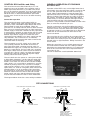
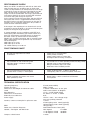
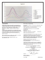
...a significant advance in marine safety!
Active-X-Band
Radar Target Enhancer
OPERATION MANUAL
Manufactured by
Echomax Products in the UK
PO Box 6032, Dunmow CM6 3AS, UK.
Email:[email protected]
www.echomax.co.uk
Tel: 00 44 (0) 1371 830216 Fax: 831733
Active-X-Band
Radar Target Enhancer
GENERAL INTRODUCTION
The Echomax Active-X Radar Target Enhancer (RTE) is designed to respond to interrogating X band radar (9.30
– 9.5GHz) by receiving a transmitted pulse and amplifying the pulse and re-transmitting the pulse back to the
radar at the same frequency with minimum delay, thereby improving the radar detection range and visibility of
small targets. It will not enhance significantly vessels with large radar cross section. Low power consumption
is an important feature of the design as the RTE may well be used where the power source is a solar panel or
wind generator with battery back up. The RTE will give an immediate response the moment it is switched on.
The RTE is primarily intended for small vessels with no radar fitted and typically should enhance
the RCS (radar cross section) of vessels up to 25M in length. For small craft /rigid inflatables improvements
will start to be seen at around 1-2 miles extending to 8-10 miles or more depending on prevailing conditions.
The performance of the RTE will vary according to a number of factors e.g. range, RTE and radar height above
sea level (due to the curvature of the earth), radar power and condition. Poor weather, sea state and
precipitation will greatly reduce the response e.g. moderate precipitation can attenuate a return signal by 70%.
Over a distance of 10nm a 10M2 target will return just 0.001M2. Please refer to www.echomax.co.uk section
Echomax in action - radar reflectors explained, where attenuation is dealt with more fully.
Owners of the Echomax Active-X may take comfort that the very high RCS response from the unit affords them
the best possible chance that the RTE response will show up consistently as a larger target by an interrogating
radar making it easier to identify as a larger target and not mistaken for clutter, helping to improve
both your safety and navigation.
IMPORTANT
The fitting of the Echomax Active-X to your vessel does
not exclude you from exercising common prudence and
safe navigational judgement for your vessel and crews
safety under the International Regulations for the
Prevention of Collisions at Sea and to keep a proper look
out at all times and take what ever action is required to
avoid a collision.
LICENSING
OFCOM- has requested that you ask them for a Letter of
Variation to include the Echomax Active-X RTE on your
VHF radio licence.
ECHOMAX ACTIVE-X COMPONENTS,
CONSTRUCTION, USE AND INSTALLATION
If you feel that there is the slightest doubt in your mind
that you are not able to safely install the unit yourself you
are advised to seek the services of a competent person
or company to install the RTE.
COMPONENTS
Echomax Active-X mast head radome fitted with 24
meters of 2 core cable
Control box
User manual
RADOME FITTING
Mast head radome is made from UV resistant
Polypropylene and contains the receiver, transmit
antenna and PCB. The antenna has provisions in the
base for a 1 inch -14 female thread mast fitting or deck
mount bracket for cabin roof or A frame.
Plastic mounts should not be used.
To ensure a permanent fixing ʻLOCTITEʼ or PTFE or
plumbers tape should be wrapped around the male thread
and the RTE must be a screwed down tightly. Care must
be taken to ensure that as the RTE is tightened on the
base the cable is not twisted but allowed to turn freely.
For mast fitting the radome must be fitted in a vertical
position as high as possible and have a clear 360 degree
azimuth. It should be fitted at least 6 inches/150mm from
the mast on the offset bracket. It should not be fitted on
a back stay or where its vision is obscured or is close to
any metal object otherwise performance could be
significantly impaired.
The radome unit must never be painted as this will
seriously impair performance.
The radome must not be fitted in or close to the vessels
Radar transmitting beam width of 23 degrees as this
may seriously damage the PCB. Whilst the RTE has built
in protection to safeguard against such damage a 30
minute plus sustained interrogation by a >15M 25KW
radar may damage the PCB.
The RTE should be fitted below or preferably above the
radar.
The unit is supplied with 24M of cable and it is preferable
that this is not joined as any such join may lead to water
penetration. Whilst a through deck plug may be used a
through deck gland is preferable. However a good and
permanent joint will not affect the performance. It is
possible to shorten or extend the cable by a further 25
meters without affecting the performance. If extension is
required a cable rated at 3A at 300V must be used. Allow
a short length of cable looped under the radome so that
any water drips from this and that strain is never applied
to the cable gland.
CONTROL BOX facilities and fitting
GENERAL OPERATION OF ECHOMAX
ACTIVE-X RTE
The control box must be fitted internally as it is not
waterproof and can be fitted in the navigation area or
within sight of the helm if this is possible. The control
box can also be flush mounted and can be wired from
the base or back as required. Ensure that there are no
electrical wires or other items behind the prescribed
location area. Check for free access for both mounting
and wire.
The control box features a triple alarm facility as
standard, namely visual green LED light flashes when
painted by radar, switchable integral buzzer will sound
when painted by radar when mobilized. There are
provisions for an 8 Amp external alarm for deck mounted
light or horn for single handed sailor or night watchman.
The 8A supply is more than sufficient for this purpose but
if more power is required an optional relay must be used
to avoid damage to the control box. A fused or circuit
breaker ships electric supply of no more than 3-5A
should be used and ideally not a direct supply from the
ships batteries. The control box has an externally
replaceable 0.5A fuse averting the need to remove the
control box from its mounting.
Control box operation
The unit requires a 12v DC supply and is surge and
cross polarity protected. Should the vessel have a
24V supply then either a dropper must be used or a
dedicated 12V supply via a 3 amp fuse box from a 12V
battery as stated above. If a long cable run is required
then larger cables must be used to ensure that there is
no power loss. The DC supply can either be negative
grounded or have both positive and negative supply
ʻfloatingʼ above the vesselʼs ground.
Operation of the RTE is easy and straight forward and
user friendly. Once the red power switch is turned on the
unit is in the quiescent mode and will consume up to
15mA. When interrogated by a radar the green LED
light will flash every 2.4 seconds. If the flash lengthens
then this indicates that more than one radar is painting
the antenna. If painted by a high speed radar which
rotates every 1.5 seconds then the LED light will flash
correspondingly quicker. If the flashing sequence
quickens is not possible to tell the number of radar in the
area as some may be painting in sync.
Turning on the green switch will mobilize the internal
buzzer, which is set to actuate for approximately half a
second at a time, once the antenna has been painted
and buzzer sounds it is considered that once alerted you
would wish to turn the buzzer off and watch for the
vessel concerned.
The control box also has facilities for an external 8A volt
free connection to the vessels own horn, deck light or
deck alarm. This facility may be very useful for the single
handed sailor or night watchman. Wiring instructions are
shown above
Whilst the control box is cross polarity protected care
should be exercised when the unit is being installed.
Should the fuse be damaged then this is located at the
base of the control box and can be replaced with the
control box in situ.
The unit is fitted with a 0.5A Quickblow 20mm fuse.
The red switch turns the power on causing the red LED
to light. When painted by a single radar the green LED
will give one short flash every 2.4 seconds. If multiple
flashes occur within 2.4 seconds this indicates multiple
radar signals. It is not possible to establish an accurate
number of painting radar at any one time as multiple
radar may be painting in sync or high speed radar will
repeat every 1.5 seconds. The green switch will turn the
integral buzzer on or off as required. The control box
has provision for seven wires, one block of two for the
extension alarm and one of five for the RTE and the
power supply and upon selecting the desired position,
may be wired from either the rear or from underneath.
The diagram below shows the correct wiring installation
RTE CONNECTIONS
BASIC OPERATION - NO EXTERNAL ALARM
PWR
0V
RTE
LNK BL BN
EXT ALRM
BROWN
SHIPS SUPPLY
+12V
OPERATION - WITH EXTERNAL ALARM
BLUE
TO ACTIVE-X ANTENNA
SWITCHED CONTACT (RELAY )
FOR EXTERNAL ALARM
PWR
0V
RTE
LNK BL BN
BROWN
0V
SHIPS SUPPLY
+12V
BLUE
TO ACTIVE-X ANTENNA
SWITCH
CONNECT ' LNK' TO ' BN'
TERMINAL. INCLUDE
SWITCH IN CIRCUIT TO GIVE
ON/OFF CONTROL OF
EXTERNAL ALARM FACILITY
PERFORMANCE CHECK
When your RTE is installed you will wish to check with
other vessels that you are being seen on their radar
screen. No improvement can be expected at close range
as the RCS of your vessel may exceed the RCS of the
RTE. The trial is best carried out at 0.5 miles as the
target can be easily identified. The range should then be
increased at intervals of 0.5 nm and the RTE switched
on and off noting the change in response.
As the range increases the bare target, with the RTE off
will not be seen and it is suggested that whilst moving
the RTE is left on so that the test target can be seen at
all times. This is especially important in busy waters to
avoid confusion with other vessels.
If the target is lost experience has shown that it can be
acquired by turning the RTE on and off and watching the
display for change in target response.
In normal weather and sea conditions, with RTE and
interrogating radar mounted at four meters above sea
level you would expect your RTE returns to appear on
the radar screen as shown below. If the mounting
heights vary so will the response due to curvature of the
earth. These figures are for guidance only and should
not be relied upon.
2KW radar up to 4 nm :
5KW radar up to 10 nm :
10- 25KW radar up to 15-20 nm
FAULT FINDING CHART
No Red LED light when red switch
is turned on
Unit switched on and continuous green
LED light shows, in harbour or when
saturating RTE
Unit on and buzzer on and unit fails to
operate when it clearly is interrogated
Buzzer switched on but does not sound
when painted by radar
TECHNICAL SPECIFICATION
Operating frequency
Position Accuracy
Dimensions and Weight of radome ex cable
Cable
Base Mounting
Dimensions of control box
Externally accessible fuse
Power supply
Stand by current consumption in quiescent state
EIRP
Radar Cross Section Response
QinetiQ – Funtington 13th March 09
Compass safe distance
Check fuse or circuit breaker
Check polarity of wiring
Check power supply at control box
Damaged cable or wrong connection
Local radar on, or radar operating moored nearby(<15M)
Moored close to large metal object
Being activated by ships own radar
Relocate to more suitable position
Check all above faults. Is RTE in shadow of
interrogating radar as it will not operate if masked
Buzzer faulty – return control box to Echomax
for inspection
X band (9.30-9.5GHz)
Within 1 meter
L 478mm W 40.5mm wt 327 grms
24M 2 core 0.5mm2 wt 969grms
1 inch – 14 NF female thread
W 92mm H 51mm D 38mm
0.5A
12V DC – 30% - 10% voltage surge
and cross polarity protected
< 15mA
5 interrogating radar 23mA (typically)
10 interrogating radar 32mA (typically)
1W (typically)
Stated Performance Level (SPL)
zero degrees
111.36M2
+/- 10 degrees of heel
78.96M2
+/- 20 degrees of heel
20.80M2
1 metre
GUARANTEE
The Echomax Active-X band RTE is guaranteed for 12
months from the date of purchase and provides for the
complete replacement at our discretion of the complete
unit or any of the components providing failure is
attributed to component failure or defect which is not
attributed to accidents, misuse, fair wear or tear or
neglect.
The guarantee is invalidated by any attempt whatsoever
to open up or interfere in any way with the unit. It is the
users responsibility to return the unit at his expense to us
to inspect and report on the reason for failure. No
exchange unit will be given until a full inspection and
report is issued.
This guarantee does not affect your statutory consumer
rights or those governed by English Law.
For comparison with competing products see
www.echomax.co.uk.
(As required by Article 6.3 of Directive 1999/5/EC-RTTE
Directive)
Declares under his sole responsibility that the active
radar target enhancer manufactured by;
Declaration of Conformity
AQUAMATE PRODUCTS LTD. t/a ECHOMAX
PO Box 6032
Dunmow
Essex CM6 3AS U.K
Telephone + 00 44 (0) 1371 830216
fax 831733
Email: [email protected]
Intended for Worldwide use as an X Band active radar
target enhancer aboard non SOLAS vessels and
identified by the type number Active-X to which this
declaration refers has been tested to the essential radio,
EMC & safety test suites required by the notified body
and is in conformity with the standards
EN60945: 2002 (Clauses 9, 10 & 12)
And complies with the essential requirements of
Directive 1999/5/EC
Conformity procedure under Annex IV of 1999/5/EC
(Technical Construction File) has been undertaken by
QinetiQ (0191) of Cody Technology Park Ively Road,
Farnborough GU14 0LX UK
The Technical Construction File is held by;John H Simpson
AQUAMATE PRODUCTS LTD. t/a ECHOMAX
PO Box 6032
Dunmow
Essex CM6 3AS U.K
Tel: 00 44 (0)1371 830216 Fax 831733
Email: [email protected]
Signed ………………………………………
John H. Simpson
Managing Director
June 2009
EMAXM 0609