1
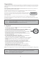
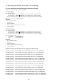
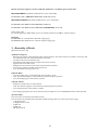
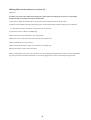
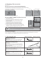
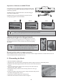
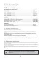
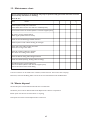
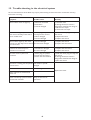
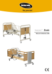
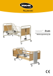
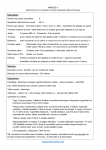
Invacare® Etude
Invacare® Etude
User’s manual (DK - S - GB - NL - D - F - ES - P)
Invacare® EC-Høng A/S
Ident. nr.: 1423886
Version 01 06.2002
Backed by a 3 year warranty on all parts
Table of Content
1.
2.
3.
4.
5.
6.
7.
8.
9.
10.
11.
12.
13.
14.
15.
16.
17.
18.
In general ....................................................................................... 34
Receiving the Etude at the place of mounting....................... 36
Assembly of Etude....................................................................... 37
Mounting of the accessories ..................................................... 39
Operating the bed ....................................................................... 39
Emergency lowering of the backrest and/or thigh section ... 40
Operating the accessories ......................................................... 40
Dismantling the Etude ................................................................... 41
Using the transport fitting ......................................................... 42
Order numbers for accessories .............................................. 42
Cleaning and disinfection ........................................................... 42
Maintenance and check-ups ...................................................... 42
Maintenance chart ....................................................................... 43
Waste disposal ................................................................................ 43
Trouble-shooting in the electrical system ............................. 44
Wiring ................................................................................................ 45
Technical specifications .............................................................. 47
Weight ............................................................................................... 47
33
Congratulations
- You have chosen an Invacare®Etude nursing bed. Etude is the detachable nursing bed from Invacare®EC-Høng
designed especially for home nursing. The Etude nursing bed provides ease of handling and combined with good
functionality.
Invacare®EC-Høng is certified according to DS/EN ISO 9001/EN 46001 which ensures that our customers are
always supplied with products of uniform quality.
Throughout the entire production process our materials/products are quality controlled by the operators.
Moreover, a final test is carried out prior to packaging and shipping.
The operator carrying out the final test, which comprises checking of all moveable
parts, motors and castors, puts his personal QA number on the product thereby
confirming its quality.
QA XXX
If the product does not correspond to the quality demands of Invacare®EC-Høng, it will be discarded.
If, contrary to our expectations, a problem should arise in connection with the delivered product, please contact
your Invacare®supplier.
Invacare®accepts no liability for any use, change or assembly of the product other than as
stated in this User’s Manual.
Accessories not mentioned in this manual must not be used.
1. In general
• The Etude bed is marked with the
mark in accordance with directive 93/42/EEC
concerning Medical Apparatus.
• The Etude bed has been tested and approved according to EN 1970:2000.
• The motors and control of the Etude bed have been approved acc. to EN 60601:1996-03.
• The Etude bed has been approved and marked with the TÜV mark.
• Beds provided with tilt function cannot be approved according to EN 1970:2000.
• The Etude bed has undergone a risk analysis according to EN 1441.
• The control and motors are protected according to IP 54. The hand control box is
protected according to IP 66.
• Max. weight: Etude Basic:180 kg - Etude Classic: 220 kg.
• Max. patient weight: 145 kg (Etude Basic) - 185 kg (Etude Classic) provided that the
weight of the mattress and the accessories does not exceed 35 kg.
• Standard size of mattress for the Etude Basic is: 90x200x12, Etude Classic: 90x200x10.
• If the patient height exceeds 2 meters it is recommended to use a mattress support
extension.
• The Etude bed has loose cables, which have to be exchanged when damaged.
• The bed is not intended for children under 12 years and psychiatric patients.
• Remove the plug from the mains voltage before moving the bed. The cable must be
kept clear off the floor and the castors during transportation.
• The adjustment area of the mattress support is: Basic: 40-80 cm or 33-73 cm,
Classic: 40-80 cm (30-70 cm/Low height version).
• Only accessories described in this manual may be mounted on the Etude bed.
• The angle between the lower leg section and horizontal is adjustable from 0º to 15º.
Note! The total weight (mattress, accessories and patient weight) may not exceed 180 kg (Basic), 220 kg (Classic).
The bed is not intended for use together with MEDICAL ELECTRICAL EQUIPMENT.
It can be dangerous to roll over the mains cable.
Do not bring mains cable into moving parts.
34
Disconnect the plug from the mains before moving the bed.
The cables must be mounted in such a way that they are kept clear off the floor and do not block
the castors.
We recommend to mount the mains cable on the hook for this purpose, see picture below.
The bed’s castors must be blocked during nursing a patient in bed or when using any positioning
function. The bed must not be moved when nursing a patient in bed.
Adjust the mattress support sections to horizontal position and lower the bed to its lowest
position before moving the bed.
Hold the top of the bed end with both hands while the bed is pushed/pulled.
Any obstacle may not be higher than 10 mm.
If the functions of the bed change, check the bed according to the maintenance chart, chapter 13.
All service and maintenance work described in chapters 11, 12 and 13 may only be performed
by personnel who have been instructed and trained by Invacare®.
The Etude bed must be stored in a room with a humidity equivalent to normal indoor conditions.
The bed must be stored in a frost-free environment.
35
2. Receiving the Etude at the place of mounting
For a complete bed the following parts must be provided:
(Illustration 1, here shown as a 2-sectioned bed)
1. Etude Basic
A) 1 mattress support
If 2-sectioned = ETUDE.CXXXX.XX (see complete list for specific number)
If 4-sectioned = ETUDE.EXXXX.XX (see complete list for specific number)
2 mattress handles, hand control and motors are mounted on the mattress support.
B) 1 pair of bed ends = ETUDE.000C1.XX
Optional:
• Pair of siderails (steel)
• Lifting pole
• Support handle(s)
• Mattress support extension (10 or 20 cm)
• Transport fitting
2. Etude Classic
A) 1 mattress support
If 2-sectioned = ETUDE.CXXXX.XX (see complete list for specific number)
If 4-sectioned = ETUDE.EXXXX.XX (see complete list for specific number)
2 mattress handles, hand control and motors are mounted on the mattress support.
B) 2 individual bed ends
If standard
= ETUDE.000EI.XX
If low
= ETUDE.000F1.XX
Optional:
• Pair of siderails (wood)
• Lifting pole
• Support handle(s)
• Mattress support extension (20 cm)
• Transport fitting
Order numbers for Etude mattress support and bed ends:
ETUDE.CE100.XX
2-SECT 90X200 STD. MAINS CABLE, TILT, NOT TÜV APPROVED
ETUDE.CE300.XX
2-SECT 90X200 STD. MAINS CABLE, EXCL.TILT, TÜV APPROVED
ETUDE.CU100.XX 2-SECT 90X200 UK MAINS CABLE, TILT, NOT TÜV APPROVED
ETUDE.CU300.XX 2-SECT 90X200 UK MAINS CABLE, EXCL.TILT, TÜV APPROVED
ETUDE.CA100.XX 2-SECT 90X200 AU/NZ MAINS CABLE, TILT, NOT TÜV APPROVED
ETUDE.CA300.XX 2-SECT 90X200 AU/NZ MAINS CABLE, EXCL.TILT, TÜV APPROVED
ETUDE.EE100.XX
4-SECT 90X200 STD. MAINS CABLE, TILT, NOT TÜV APPROVED
ETUDE.EE300.XX
4-SECT 90X200 STD. MAINS CABLE, EXCL.TILT, TÜV APPROVED
ETUDE.EU100.XX
4-SECT 90X200 UK MAINS CABLE, TILT, NOT TÜV APPROVED
ETUDE.EU300.XX
4-SECT 90X200 UK MAINS CABLE, EXCL.TILT, TÜV APPROVED
ETUDE.EA100.XX
4-SECT 90X200 AU/NZ MAINS CABLE, TILT, NOT TÜV APPROVED
ETUDE.EA300.XX
4-SECT 90X200 AU/NZ MAINS CABLE, EXCL.TILT, TÜV APPROVED
ETUDE.EJ100.XX
4-SECT 90X200 JPN. MAINS CABLE/100V, TILT, NOT TÜV APPROVED
ETUDE.EJ300.XX
4-SECT 90X200 JPN. MAINS CABLE/100V, EXCL.TILT, TÜV APPROVED
36
All the mattress supports can be combined with these 3 available types of bed ends:
BED ENDS BASIC (Ordered and delivered as a pair of bed ends)
ETUDE.000C1.XX 1 PAIR BASIC BED ENDS, 40-80 CM (33-73)
BED ENDS CLASSIC (Ordered and delivered as 1 pcs. of bed end)
ETUDE.000E1.XX 1 PCS. CLASSIC BED END, 40-80 CM
ETUDE.000F1.XX 1 PCS. CLASSIC BED END LOW HEIGHT, 30-70 CM
XX is colour code.
For standard light grey (RAL 7032) .21 is to be used for bed ends and .20 for mattress support.
Example:
ETUDE.000E1.21 (1 Etude Classic bed end in light grey)
ETUDE.EE100.20 (1 Etude 4-sect. mattress support in light grey)
3. Assembly of Etude
(Illustration 2a, 2b+c, 2d)
a) Mattress Support
- Place the two inserts in the head end of the mattress support. The inserts must be mounted in such a way that
one extends further out of the side tube than the other.
- Loosely screw in the two thumb screws.
- Push the foot end of the mattress support onto the two inserts.
- Tighten with two thumb screws.
- Retighten the two thumb screws at the head end of the top frame.
- Turn the two mattress handles of the backrest up.
- Turn the handle of the leg section up.
b) Etude Basic
- Turn the locking rings*) on the bed ends to the position „open“.
- Latch the mattress support to the bed ends and press firmly into position.
- Turn the locking rings to the position „locked“.
c) Etude Classic
- Release the quick locks*) on the bed ends.
- Latch the mattress support to the bed ends and press firmly into position.
- Turn the quick locks to the position „locked“.
*)
The locking rings/quick locks ensure that the mattress support is not accidentally lifted clear of the bed ends.
d) Control Box
The control box is latched to the backrest motor.
The control box is provided with a label with symbols showing where to connect the motors’ plugs.
- 1: Backrest motor
- 2: Thigh section’s motor
- 3: Bed end
- 4: Bed end
- HB: Hand control
37
Wiring (Also see the pictures in section 16)
Attention!
In order to prevent the cables from being torn apart when activating the motors it is absolutely
important that you follow the below instructions:
1) Connect the cables of the bed end motors (head and foot end) directly to the control box.
2) Only 4-sectioned beds: The plug of the thigh motor must be directed through the opening of the supporter
for the backrest motor and then be connected to the control box.
3) Connect the mains cable to the 230V plug.
4) Run the motors of the bed ends to their top position.
5) Place the motor cable of the foot end on the hook at the foot end.
6) Run the backrest to its top position.
7) Place the head end motor cables on the 4 hooks at the head end.
8) Fasten the safety comb to the control box.
When working with the foot end, note that there is a risk of getting squeezed during transport since the adjustable
leg section is not firmly locked. Remember to remove the plug from the mains socket when moving the bed.
38
4. Mounting of the accessories
(Illustration 3)
Mounting of siderail, model 5519/5525/5526/5529
The siderail may be mounted with the release system at the head of the bed.
The fork links on the siderail must be mounted according to
the instruction on the siderail.
0 - 6 cm
1)
25 cm or more
2)
1)
2)
Tighten the siderail with 2 thumb screws.
A
Mounting of BRITT II/BRITT III (Classic bed ends)
1. Raise the bed about 1/3.
2. Dismount the stop-knobs using the thumb screws (C).
3. Dismount protection tape at the locking pins at both
ends of the siderail.
4. Mount one end at a time. Lift the lower wooden bar
and guide the metal bow to the bed end rail (A).
5. Press the locking pin of the siderail with a finger (B).
6. Guide the siderail to the bed end and pull up the wooden
siderail bar, until the locking pin locks with an audible click.
7. Mount the stop-knobs using the thumb screws (C).
C
B
There is a risk of squeezing fingers on assembly and operation of the siderails.
Mounting the lifting pole
Remove the plug from the lifting pole tube at the head end of the bed where the lifting pole is to be placed.
Insert the lifting pole into the lifting pole tube and fix with the thumb screw.
5. Operating the bed
Electric operation
Adjustment of backrest
(Illustration 4)
Raising or lowering the backrest to the required angle:
Use the button with the symbol shown on the right.
Adjustment of the leg section
(Illustration 5)
Use the handle when raising or lowering the leg section.
Raising or lowering the leg section to the required angle:
UP: Lift the leg section.
DOWN: Lift the leg section right up and then lower it.
Adjustment of the thigh section
(only 4-sectioned beds) (Illustration 6)
Use the button with the symbol shown on the right.
Adjustment of height of mattress section
(Illustration 7)
Use the button with the symbol shown on the right.
39
Manual operation
Always leave the bed in the lowest position. Otherwise there is a risk of getting squeezed due
to accidental lowering of the mattress support. A person under the bed can be seriously injured
during height adjustments.
There is a risk of getting squeezed between the thigh section and the mattress support when the
thigh section is lowered.
There is a risk of getting squeezed between the backrest and the cross rail on the head end of
the mattress support. There is also a risk of getting squeezed between the leg section and the
cross rail on the foot end of the mattress support when the backrest/leg section is lowered.
If the bed is equipped with tilt function, please note that the bed must not be used without the
supervision of the nursing staff.
Brakes
(Illustration 8)
Each of the bed’s 4 wheels is provided with brakes for both lengthwise and crosswise locking.
The brake is foot-operated.
6. Emergency lowering of the backrest and/or thigh section
(Illustration 9)
An emergency release of the mattress support may be necessary in case of e.g. a power or motor failure. An
emergency release of the height adjustment is NOT possible!
- Remove the plug from the mains before emergency release of the mattress support.
- In an emergency the mattress sections are released by pulling out the cotter pin from the motor.
A minimum of 2 persons is required to release a mattress section. Both persons hold the
mattress section in locked position. One of them pulls out the cotter pin.
Both slowly lower the mattress section until it is completely down.
7. Operating the accessories
Operation of siderail, model 5519/5525/5526/5529
(Illustration 10)
UP: Pull the top tube on the siderail towards the end where the release system is placed.
DOWN: Press the release button down while pulling the top tube away from the release system.
40
Operation of siderail, model BRITT II/III
Locking pins
The bed end may be equipped to lock the siderail at half height
as well as in the top position. Normally the siderail can only be
locked in top position.
UP: Pull up the top wooden siderail bar, until the locking pin
locks with an audible click.
DOWN: Lift the top wooden siderail bar and press the two
locking rings together. Lower the siderail.
Raise
Release
Lower
There is a risk of getting squeezed when operating the siderails.
Adjusting the height of the lifting pole handle
Loosen the cord as shown in fig. A. The lifting handle can now be
adjusted to the desired height. Press the cord together as shown in
fig. B and check that the cord is locked in the cord lock by pulling
the handle.
Position the lifting pole in such a way that the handle
extends inwards across the bed. If the lifting pole is
used while the handle has been turned away from the
bed - the bed can tip when the handle is used.
A
B
Mounting of the mattress support extension
Disassemble the bed and remove the inserts. Mount the mattress support extension on either head or foot end
and reassemble the bed. (See illustration 2).
8. Dismantling the Etude
• Dismount siderails and lifting pole.
• Bring the bed to its lowest position and adjust all mattress support sections to horizontal position.
• Disconnect the 230 V supply. Roll the cable onto the hook of the head end of
the bed.
• Disconnect all the motor plugs from the motors (do not disconnect the
backrest motor cable - cable 1).
• Dismantle the safety comb from the control by means of a tool, e.g. a
screwdriver.
• Pull out the cables of the bed end motors. Only 4-sectioned: Also pull out
the cables of the leg section motors.
• Separate the mattress support from the bed ends.
• Divide the head and foot end of the mattress support.
41
9. Using the transport fitting
See instructions for use on transport fitting.
10. Order numbers for accessories
General (Etude Basic + Etude Classic)
Lifting pole .......................................................................................................................................................
Mattress handle ..............................................................................................................................................
Transport fitting ..............................................................................................................................................
Support handle 25x30 cm (1 pcs.) ...........................................................................................................
Support handle 25x80 cm (1 pcs.) ...........................................................................................................
Support handle 40x30 cm (1 pcs.) ...........................................................................................................
Support handle 40x50 cm (1 pcs.) ...........................................................................................................
Support handle 40x95 cm (1 pcs.) ...........................................................................................................
50.57600.XX
215989
1423920-7032
021964.20
1417510-7032
1417511-7032
021963.20
1417512-7032
Etude Basic
Siderail (folding) 1 pcs. right and 1 pcs. left ..............................................................................................
Siderail (folding) 1 pcs. right and 1 pcs. left (25 mm tube) ....................................................................
Siderail (folding) 1 pcs. right and 1 pcs. left (with plastic insert) ..........................................................
Extended siderail (folding) 1 pcs. right and 1 pcs. left ............................................................................
Mattress support extension - 10 cm ...........................................................................................................
Mattress support extension - 20 cm ...........................................................................................................
50.55190.XX/L+R
50.55250.XX/L+R
50.55260.XX/L+R
50.55290.XX/L+R
1423993-XXXX
1423994-XXXX
Etude Classic
Wooden siderail Britt III (pair) .................................................................................................................... 020434.01
Extended wooden siderail Britt II (pair) +20 cm ..................................................................................... 019376.01
Mattress support extension - 20 cm ........................................................................................................... 1423994-XXXX
11. Cleaning and disinfection
Remove the mains plug from the socket before cleaning.
The Etude bed does not tolerate cleaning in an automatic washing plant or using water-jet based cleaning
equipment.
The bed should be washed down using a sponge, cloth or brush. Use ordinary household cleaning agents.
When disinfecting only use spray or wisping methods. Only officially recognized disinfectants must be used.
Dry the bed after cleaning.
Never use acids, alkalines or solvents such as acetone or cellulose thinner.
The hand control box, motors and control may be washed with brush and water, but not with pressurized water.
If the backrest is raised be careful not to lower it unintentionally, with the risk of getting squeezed between the
backrest and the top frame.
12. Maintenance and check-ups
Service and maintenance of the Etude bed may only be performed by personnel who have received the necessary
instruction or training.
After three months of use thumb screws should be checked for tightness and the mechanism of the siderail locking
and motion should be checked.
With normal everyday operation the instructions of the maintenance chart, chapter 13, must be followed once a
year.
Check the bed and particularly the the cables, plugs and the condition of the siderails
after each use.
42
13. Maintenance chart
Service and maintenance of the Etude may only be performed by personnel who have received
the necessary instruction or training.
Bed / Id. no.:
Date:
Initials:
Visual inspection of all parts of the bed.
(Plastic deformation and/or wear and tear of welded joints).
Control of all centers of rotation (Motors + mattress support parts).
All motors running without failures.
(With regular speed and at low noise).
Check of the rastofix fittings and their function.
Visual inspection of all cabinets looking for damages.
Check that mains cable and plug are intact.
Check the running of the cable.
Check all remaining cables for damages.
Also check the running of the cables.
Check of siderails´ fixing and locking/movement.
Check the wheels (Security, braking and free rolling)
The following parts must be lubricated:
Centres of rotation (Motors and mattress support parts)
Centres of rotation of the ratofix fitting
A service contract can be made in the countries, where Invacare®has its own sales company.
Moreover, Invacare®EC-Høng offers courses in service and maintenance of the Etude bed.
14. Waste disposal
All wooden parts must be dismounted and sent to incineration.
All electric parts must be dismounted and be disposed of as electric components.
Plastic parts must be sent to incineration or recycling.
Steel parts and castors must be disposed of as waste iron.
43
15. Trouble-shooting in the electrical system
Service and maintenance of the Etude may only be performed by personnel who have received the necessary
instruction or training.
Symptom
Possible cause
Remedy
Mains indicator does not light up
1) Mains not connected
2) Fuse blown
3) Control damaged
1) Connect mains
2) Change the fuse, if control is
designed for external fuse change or
send control to repair
3) Send control to repair
Mains indicator lights up, but motor
does not run. The relays in the control
give an audible click
1) Motor plug not pushed
correctly into the control
2) Motor damaged
3) Control damaged
1) Push the motor plug correctly into
the control
2) Replace the motor
3) Replace the control
Mains indicator lights up, but motor 1) Control damaged
does not run. No relay sound is heard 2) Control box damaged
from the control
1) Replace the control
2) Replace the control box
Control is in order except one
direction on one channel
1) Control box damaged
2) Control damaged
1) Replace the control box
2) Replace the control
No motor noise or piston rod
movement
1) Motor plug not pushed
correctly into the control
2) Fuse in the control blown
1) Push the motor plug correctly into
the control
2) Change the fuse, if control is
designed for external fuse change or
replace the control
The motor is running, but the spindle Gear wheel or spindle
does not move
damaged
The motor cannot lift full load
Motor damaged
Replace the motor
Motor noise, but no movement of
piston rod
Piston rod will only operate inwards
and not back outwards
Safety nut has become
operational
44
16. Wiring
1. Mount the bed. Net cable in 230 V plug.
2. Connect the cables of the bed end motors (head
and foot end) to the control box. The cables must
hang loose.
Cable number: 02770-150-1250.
3. Run the bed to the top position.
4. Place the foot end motor cable in the hook by the
foot end. The backrest must be in horizontal position.
5. 4-sec. bed: The plug of the thigh motor must be
directed through the opening of the supporter for the
backrest motor and then connected to the control box.
Cable number: 0277011-1250.
6. Place the head end motor cables in the four hooks
by the head end. The backrest must be raised.
45
Exchange of control box and cables
ATTENTION: The control box must always be placed with the plugs face up.
1. The control box can be removed by
removing the fastener clips from the
backrest motor.
Fastener clips
2. Pull the control box in sideways
position from the motor.
3. The control box and/or cables can
now be exchanged.
46
17. Technical specifications
All measurements are stated in cm. All angles are stated in degrees. All measurements and angles are stated
without tolerances.
Invacare®reserves the right to change the stated measurements and angles.
(Illustration 11)
Voltage supply: 230 V ~ ±10%, 50 Hz.
Max. current input: 1 A.
Voltage output: 24 V ~ max. 70 VA
Intermittent (periodic motor operation): 10%, max. 6 min/h.
Protection class: IP 54.
Insulation class: II, type B.
The patient is not separated from the ground and the chassis.
Double insulated.
The bed is not provided with a mains switch, so the mains plug is the only separation from the mains.
= Basic: 180 kg
Classic: 220 kg
}
- Max. load (SWL)
(Patient + mattress + siderail + lifting pole + other equipment)
Sound level: 45-50 dB (A)
18. Weight
Basic bed end - 1 piece
Classic bed end - 1 piece
Mattress support, head end
Mattress support, foot end, 2-sectioned
Mattress support, foot end, 4-sectioned
Siderail - 1 piece
Lifting pole
Mattress support extension (10 cm)
Mattress support extension (20 cm)
17
24
22
17
22
7
7
3,2
5,5
2-sectioned bed, complete, excluding accessories
with Basic bed ends
4-sectioned bed, complete, excluding accessories
with Basic bed ends
kg
kg
kg
kg
kg
kg
kg
kg
kg
73 kg
78 kg
2-sectioned bed, complete, excluding accessories
with Classic bed ends
4-sectioned bed, complete, excluding accessories
with Classic bed ends
87 kg
92 kg
47
®
Invacare Australia
1 Lenton Place
North Rocks NSW 2151 Australia.
www.invacare.com.au
email: [email protected]
Phone 1800 460 460
Fax: (02) 8839 5311