1
R&D
Carbon Ltd.
USER'S MANUAL
Rev. 02/2000
RDC-141
COKE CO2 REACTIVITY
APPARATUS
- IMPORTANT NOTICE -
This manual contains important instructions regarding the
SAFETY, INSTALLATION, OPERATION AND MAINTENANCE
of this machine which must be
STRICTLY FOLLOWED.
Rev. 02/2000
II
RDC-141, User's Manual
RDC-141
COKE CO2 REACTIVITY
APPARATUS
MANUFACTURER'S NOTICE
(1)
This manual should be CAREFULLY and COMPLETELY READ before attempting to install, operate or maintain this equipment.
(2)
This equipment has been tested in the RDC quality control laboratory
and was found to be operating correctly prior to delivery. If for any reason some difficulties are encountered in the installation, operation
and/or maintenance of this equipment please contact our Test Apparatus Department at:
R & D Carbon Ltd.
P.O. Box 362
CH-3960 Sierre
SWITZERLAND
Phone : +41 / 27 - 459 29 29
Fax
: +41 / 27 - 459 29 25
Rev. 02/2000
III
RDC-141, User's Manual
TABLE OF CONTENTS
Page
SECTION 1. INTRODUCTION
1
SECTION 2. DESRIPTION OF APPARATUS
4
2.1
2.2
2.3
2.4
6
2.5
7
5
5
6
Tube Reactor
Thermocouple
Furnace
Control Box
Tempreature Control Unit
SECTION 3. SAFETY INSTRUCTIONS
8
3.1
3.2
3.3
3.4
3.5
9
10
10
11
11
General
Safety Regarding Installation
Safety Regarding Operation
Safety Regarding Maintenance
Warning Labels on the RDC-145 Apparatus
SECTION 4. INSTALLATION
4.1
13
4.2
14
4.3
14
4.4
16
4.5
16
12
Installation Site
Unpacking
Assembly Instructions
Pre-operation Inspection
Calibration
SECTION 5. OPERATION
Rev. 02/2000
18
IV
RDC-141, User's Manual
5.1
5.2
19
5.3
Principle
Sampling and Sample Size
19
Procedure
20
SECTION 6. MAINTENANCE
21
6.1
6.2
22
6.3
23
6.4
24
6.5
24
6.6
25
6.7
25
6.8
26
6.9
6.10
27
22
General
Replacing the Furnace
Replacing the Heating Element
Replacing the Temperature Controller
Replacing the Thermocouple
Replacing the External Reactor Tube
Replacing the Triac
Replacing the Control Unit for Gas & Furnace Control
Replacing the Transformer
Periodical Control
26
APPENDICES
28
Appendix A. Technical Drawings
29
Appendix B. Spare Parts List
31
Rev. 02/2000
1
RDC-141, User's Manual
Section 1.
INTRODUCTION
Rev. 02/2000
2
RDC-141, User's Manual
1. INTRODUCTION
The influence of raw materials on the properties of pre-baked anodes can be predicted if correlations between raw material production parameters, raw material
properties, anode quality and anode behaviour during electrolysis are known. Such
predictions enable the utilisation of good quality, low cost raw materials which can
significantly influence aluminium production costs.
Typical prebaked anodes for aluminium production consist of 65% petroleum
coke. At constant temperature, different cokes have distinctly different reactivities,
the difference being up to an order of magnitude. This can be due to the method of
coke manufacture and hence its microstructure, porosity, heat treatment temperature and purity.
Carbon reacts with carbon dioxide according to the endothermic reaction:
CO2(g) +
(1)
C(s)
2CO(g)
This reaction, often referred to as the Boudouard or carboxy reaction, is temperature dependent with the thermodynamically-favoured product being almost all carbon monoxide at temperatures greater than 900 °C (1652 °F). In aluminium production where electrolytic cells operate at 950-960 °C (1742-1760 °F), carbon
dioxide, generated at the anode interface by electrochemical oxidation, can attack
the carbon anode by such a reaction. This may occur at the interface surface or on
the submerged sides beneath the crust as the evolved carbon dioxide sweeps
around the anode and is discharged from the cell. Such attack leads to excess
carbon consumption as the anode is consumed without any metal deposition.
The carboxy reactivity of a calcined petroleum coke can be measured by determining the weight loss of a sample exposed to carbon dioxide at a temperature sufficient to give reaction according to the chemical reaction described in equation 1.
This figure allows an assessment of the later carboxy reactivity in the electrolytic
cell of anodes made from this coke.
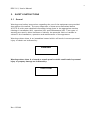
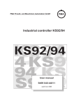
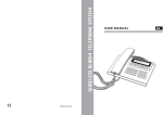
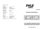
The carboxy reactivity of calcined petroleum coke can be measured using the
RDC-141 apparatus described in this manual. A schematic diagram of the apparatus is shown in figure 1.
Rev. 02/2000
3
RDC-141, User's Manual
Figure 1
Rev. 02/2000
RDC-141 Coke CO2 reactivity apparatus
(dimensions in millimeters ; 25,4 mm = 1")
4
RDC-141, User's Manual
Section 2.
DESCRIPTION
OF APPARATUS
Rev. 02/2000
5
RDC-141, User's Manual
2. DESCRIPTION OF APPARATUS
The RDC-141 apparatus consists of a tube reactor, a furnace, a temperature controller and a microprocessor for controlling the gas and furnace operations, a CO2
flow meter and pressure control system and a display panel providing information
on the status of the furnace and sample. An apparatus (RDC-141) was shown previously in
figure 2.
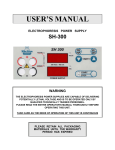
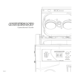
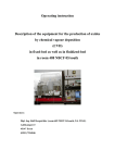
2.1 Tube Reactor
The tube reactor consists of two quartz
tubes and a cover which are assembled as
shown in Figure 2. The flow of CO2 gas
into the reactor tube is via the gas
inlet and exterior to the inner tube, allowing the gas to be preheated before flowing
upwards through the fritted disc and petroleum coke sample, and out the gas
outlet in the cover. The fritted disc has a
pore size of 250 - 500 µm and the tip of
the protection tube containing the thermocouple lies 5mm underneath it.
Air out
Air in
FURNACE
Quartz
fritted disc
250-500µm pore size
5g Carbon sample
sample + 1-1.4 mm
Thermocouple Chromel Alumel 2mm
2.2 Thermocouple
A chromel-alumel K-type thermocouple
having a precision better than ± 0.375%
according to the DIN 43710 standard is
used to measure the temperature. It
should have a diameter of 2 mm and a
length of 200mm.
Figure 2 Tube Reactor Assembly
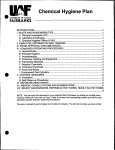
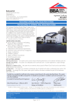
2.3 Furnace
The furnace should ensure a good vertical temperature distribution and a heating
time from 20 to 1000C of less than one hour. To meet these requirements necessitates constructing a furnace with kanthal heating elements having vacuum
Rev. 02/2000
6
RDC-141, User's Manual
formed, ceramic fibre insulation.
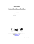
The dimensions of the furnace, including a holder for the tube reactor assembly are
100
25
20
9
52
8
36
40
50
220
50
160
Figure 3 Furnace Dimensions and Characteristics
shown in figure 3.
2.4 Control Box
The front
-
panel of the control box consists of:
a "MAIN SWITCH" and associated lamp (light emitting diode or LED).
an "ON" button for starting the furnace.
a valve for regulating the inlet pressure to 2 bars.
a pressure gauge having a full-scale of 10 bars (145.0 psi).
a rotameter with a calibrated scale for CO2 gas (at p = 1 atm) having a
full-scale of 60l/h and a precision better than ±2%.
- a "SAMPLE IN" switch for starting the test cycle immediately after introduciton the sample
- 4 lamps giving information on the status of the analytical cycle (see section # 4) labelled "FURNACE ON", "CO2 ON", "SAMPLE IN", "SAMPLE
OUT".
The side panel of the control box consists of:
- Power line filter with IEC Inlets and 2 fuses (6.3 A). The electrical connection (cable) is delivered with the unit.
- the CO2 connection.
- a calibration dial that controls how long the sample remains at 1000C.
Rev. 02/2000
7
RDC-141, User's Manual
2.5 Temperature Control Unit
A two point temperature DPID controller with set value adjuster (adjustment error
<0.5%) and digital temperature display is used to control the temperature. A microprocessor inside the control box controls the heating/cooling cycle, the on/off
switching of the gas flow and the illumination of the status lamps.
Rev. 02/2000
8
RDC-141, User's Manual
Section 3.
SAFETY INSTRUCTIONS
Rev. 02/2000
9
RDC-141, User's Manual
3. SAFETY INSTRUCTIONS
3.1 General
Warnings and safety instructions regarding the use of the equipment are provided
throughout this manual. The most important of these are summarised below
(#3.2-3.4) with more detailed information being given in the appropriate section
relating to installation (#4), operation (#5) and maintenance (#6). Two types of
warning are used in these sections to identify the potential risks or hazards involved in the installation, operation and maintenance of the apparatus
Warnings where there is an immediate hazard which will result in severe personal
injury or death are indicated by:
DANGER
Warnings where there is a hazard or unsafe practice which could result in personal
injury or property damage are indicated by:
CAUTION
Rev. 02/2000
10
RDC-141, User's Manual
3.2 Safety Regarding Installation
It is the owner's responsibility to select a proper location for the RDC-141 apparatus. The installation should be undertaken only in compliance with all applicable
state and local fire and building codes.
WARNING
TO REDUCE THE RISK OF
PERSONAL INJURY OR PROPERTY DAMAGE:
a.
Install equipment in a WELL VENTILATED area or
FUMEHOOD.
b.
DO NOT install closer than 25 centimeters (10
inches) to any wall or door.
c.
Use a QUALIFIED ELECTRICIAN for wiring.
d.
Equipment must be properly GROUNDED
3.3 Safety Regarding Operation
Although the RDC-141 apparatus is operated and controlled electronically, the user
must nevertheless perform several manual tasks.
WARNING
TO REDUCE THE RISK OF
PERSONAL INJURY OR PROPERTY DAMAGE:
a.
b.
Keep hands and arms CLEAR of furnace surface.
ALWAYS wear PROTECTIVE GLOVES when handling samples.
c.
Ensure gas outlet remains unblocked.
d.
Measure ONLY carbon samples.
3.4 Safety Regarding Maintenance
It is the owner's responsibility to ensure that only trained or appropriately qualified
Rev. 02/2000
Electrical
hazard
RDC-141, User's Manual
personnel undertake any form of maintenance on the
WARNING
TO REDUCE THE RISK OF
PERSONAL INJURY OR PROPERTY DAMAGE:
a.
ALWAYS UNPLUG equipment BEFORE attempting
repairs.
b.
WAIT until furnace is completely COOLED before
interior surfaces.
RDC-141 apparatus.
3.5 Warning Labels on the RDC-141 Apparatus
The warning labels that appear on the apparatus and their location are depicted
below.
It is the owner's responsibility to ensure that these warning labels remain in place
and can be read for the lifetime of the equipment. Replacement warning labels can
be obtained from R&D Carbon Ltd. at the address or contact numbers given at the
beginning of this manual.
Only warning labels against electrical hazards are displayed on the RDC-141 apparatus. These consist of black markings on a yellow background. Two such labels
are attached to the control box - one on the removable back grill and the other inside the control box on the reverse side of the front panel.
Rev. 02/2000
11
12
RDC-141, User's Manual
Section 4.
INSTALLATION
Rev. 02/2000
13
RDC-141, User's Manual
4. INSTALLATION
4.1 Installation Site
It is the owner's responsibility to select a proper location for the RDC-141 apparatus. The installation should be undertaken only in compliance with all applicable
state and local fire and building codes. As each furnace has a power rating of 2
kW (1.9 Btu/sec) it is advisable to keep the apparatus a reasonable distance from
any building structure (wall or door) that is not heat-resistant.
CAUTION
TO AVOID A FIRE HAZARD
Do not install closer than 25 centimetres (10
inches) to any wall or door.
As one of the gaseous products of the reaction may be carbon monoxide the apparatus must be placed in a well ventilated location. This is particularly important if
the site is a small room having no windows or skylight and an entrance that can be
closed (such as a door). Each sample has a typical weight of 5 g and in a bad
case up to 15 % of this initial weight may be consumed by reaction prior to ignition. From equation 2, it can be calculated that a 5 g carbon sample may yield up
to 3.4 g carbon monoxide. Consequently, if a test is run eight times a day using
such samples, the CO produced in a 24 hour period is 28 g. The Threshold Limit
Value (TLV) for carbon monoxide is given in the CRC Handbook of Chemistry and
Physics (p. D-125) as 50 ppm or 55 mg/m3. Therefore for a 100 m3 (3530 ft3)
"closed" room, where CO loss is negligible, the TLV will be reached in less than
two hours.
DANGER
TO AVOID EXPOSURE TO EXCESSIVE LEVELS
OF CARBON MONOXIDE GAS
The RDC-141 apparatus must be installed in a well ventilated room
or fumehood where fresh air is continuously being recycled.
Rev. 02/2000
14
RDC-141, User's Manual
4.2 Unpacking
The RDC-141 apparatus will be sent in a wooden crate that rests on "feet" so allowing transportation by forklift and also ensuring that it is not delivered upside
down. The top cover and a side panel can be unscrewed to allow access to the
apparatus. Before removal from the crate, all support panels (used to keep the apparatus rigidly in place during shipment) should be taken out and the plastic covering pulled off. The apparatus can be lifted out manually or with a crane and should
be supported at the base. The total weight of the apparatus is 45 kg (=100lb).
4.3 Assembly Instructions
The RDC-141 apparatus has been completely assembled, checked and found to be
operating correctly prior to shipment. A visual inspection should be carried out for
any obvious signs of damage that may have occurred during transportation. This
should also include a check that the thermocouples are still in place and that the
two electrical cables are still plugged into the furnace (red to red, black to black).
The quartz reactor tubes and any additional spare parts that may have been ordered will be packed separately in the same crate. These should be checked with
the packing list to ensure that all specified items have been delivered.
Once located in the appropriate site (see #3.2) the gas and electrical connections
can be made at the bottom left corner of the side panel on the control box.
The electrical wiring of the apparatus to the mains power supply should be carried
out only by a qualified electrician. The apparatus can be grounded by connecting
the earth wire of the existing cable to the appropriate pin on the plug to be used.
(This plug is not supplied with the equipment).
DANGER
TO AVOID SERIOUS PERSONAL INJURY
The RDC-141 apparatus must be
properly grounded.
To insert the
assembly carry out the following steps:
(1)
(2)
sample holder
Insert the external tube carefully and fix it with the clamping device.
Tilt the apparatus backward and put the thermocouple completely into the
protection tube by passing it through the hole in the bottom panel.
(3)
Insert the reaction tube into the external tube.
Rev. 02/2000
15
RDC-141, User's Manual
(4)
(5)
Adjust the height of the thermocouple so the tip is 5mm from the bottom of
the fritted disc in the reaction tube.
Fix the thermocouple to the frame.
The CO2 gas should be of the following gas quality:
CO2 better than 99.5 %
N2 + Ar < 0.5 %
H2O < 150 mg/Nm3, 9.4 x 10⁻⁶ lb/Nft3
The inlet pressure should not exceed seven (7) bar (101.5 psi) and appropriate
tubing should be used from the gas supply line to the apparatus. Where plastic
tubing is to be used, the following specifications apply:
external diameter:
internal diameter:
pressure/temperature:
6 mm (0.236 inch)
4 mm (0.157 inch)
to withstand 10 bar (145.0 psi) minimum at
a temperature of 80°C (176 °F).
The apparatus is designed to withstand a maximum pressure of 10 bar (145.0 psi)
and any pressures greater than this may result in damage and personal injury (for
example, bursting of the pressure gauge).
DANGER
TO AVOID SERIOUS PERSONAL INJURY
AND DAMAGE TO THE APPARATUS
The inlet pressure of the gaseous
air must not exceed 7 bar (101.5 psi).
4.4 Pre-operation Inspection
Prior to operating the RDC-141 apparatus a series of checks should be implemented.
(1)
(2)
(3)
(4)
(5)
Turn on the main switch on the front panel.
Set the calibration dial on the side of the control box to 100 minutes.
Set the temperature controller on the front panel to 1000C.
Insert the empty inner quartz tube and fix the cover with the clamp.
Activate the furnace and the gas by pushing the "FURNACE ON" button.
The lamps "Furnace on"
"CO2 on"
"Sample out" are alight.
(6) Regulate the gas pressure to 2 bar by turning the valve on the control panel
directly below the pressure gauge.
Rev. 02/2000
16
RDC-141, User's Manual
(7)
(8)
(9)
Regulate the gas flow rate to 50 L/h by turning the valve on the rotameter.
When the furnace temperature has stabilised at 1000C, an alarm will
sound.
Calibrate the apparatus as outlined in #4.5.
4.5 Calibration
The calibration procedure should be performed once a week and after any maintenance of the apparatus (reactor tube or thermocouple replacement etc).
(1)
(2)
(3)
(4)
(5)
(6)
(7)
(8)
(9)
(10)
(11)
(12)
(13)
(14)
(15)
Turn on the main switch on the front panel.
Set the calibration dial on the side of the control box to 100 minutes.
Set the temperature controller on the front panel to 1000C.
Insert the empty inner quartz tube and fix the cover with the clamp.
Activate the furnace and the gas by pushing the "FURNACE ON" button.
The lamps "Furnace on"
"CO2 on"
"Sample out" are alight.
Regulate the gas pressure to 2 bar by turning the valve on the control panel
directly below the pressure gauge.
Regulate the gas flow rate to 50 Nl/h by turning the valve on the rotameter.
When the furnace temperature has stabilised at 1000C, an alarm will
sound.
After the standby temperature is reached, the weighed standard sample
(5±0.001g) can be placed in the inner quartz tube and the cover refixed
with the clamp. The calibration standard is provided by R&D Carbon Ltd.
who have carried out a round robin involving at 10 apparatus measuring at
least one coke sample so that the average value can be statistically guaranteed.
Press the "SAMPLE IN" button to start the measurement cylce.
The lamps "Furnace on"
"CO2 on"
"Sample in"
are alight.
After 100 minutes the furnace will switch off automatically and 45 minutes
later an alarm will sound.
Take the internal reaction tube out and place it in the holder to cool for about
10 minutes.
Reset the furnace and the gas by pushing the "FURNACE ON" button.
None of the lamps will be alighted.
Weigh the remaining sample to a precision of ±0.001 g.
Calculate the reactivity in % weight loss as follows:
func R sub {CO sub 2} ~ = ~ {initial weight ~ - ~ final weight} over {initial weight}
~CDOT ~ 100 over 1 %
(16) Set the new calculated time on the calibration dial according to the equation:
Rev. 02/2000
RDC-141, User's Manual
func TIME ~=~ {func R sub {CO sub 2}~ Standard value} over {func R sub {CO sub
2}~ Measured Value}~ CDOT ~100
(17) Check the calibration with a new standard sample.
(18) The apparatus is now ready for routine measurement.
Rev. 02/2000
RDC-141, User's Manual
Section 5.
OPERATION
Rev. 02/2000
RDC-141, User's Manual
5. OPERATION
It is the owner's responsibility to ensure that the operator is properly trained and
instructed on how to use the RDC-141 apparatus.
5.1 Principle
A sample of petroleum coke is placed in a reactor tube and heated in an atmosphere of CO2, for approximately 100 minutes at a temperature of 1000C. The
weight loss due to the chemical reaction in equation 1 (see section 1) is then
measured.
5.2 Sampling and Sample Size
A representative sample of calcined petroleum coke is taken from the whole in accordance with ISO Doc. 6375. This is divided into three fractions by sieving according to the procedure ISO Doc. 2325:
I
IIa
III
> 1.4 mm
1 - 1.4 mm
<1.4 mm
Fraction I is crushed so that most of the fraction
IIb
1 - 1.4 mm
is obtained after sieving. Fractions IIa and IIb are then thoroughly mixed, and the
mixture dried at 120±2C to constant weight.
Many granular materials are coated with oil, for example to control dust formation
during processing. If this is the case, the sample material must be rinsed with Methylene Chloride before drying to remove the oil according to the procedure outlined in ISO Doc. 8723.
5±0.001g of sample are weighed for the test measurement.
5.3 Procedure
Before measuring the first sample, the pre-operation inspection described in the
installation section (#4.4) and the calibration procedure (#4.5) should be undertaken. Once this has been completed the procedure described below can be folRev. 02/2000
RDC-141, User's Manual
lowed.
(1)
(2)
(3)
(4)
(5)
Turn on the main switch on the front panel.
Set the temperature controller on the front panel to 1000C.
Insert the empty inner quartz tube and fix the cover with the clamp.
Activate the furnace and the gas by pushing the "FURNACE ON" button.
Regulate the gas pressure to 2 bar by turning the valve on the control panel
directly below the pressure gauge.
(6) Regulate the gas flow rate to 50 Nl/h by turning the valve on the rotameter.
(7) When the furnace temperature has stabilised at 1000C, an alarm will
sound.
(8) After the standby temperature is reached, the weighed sample (5±0.001g)
can be placed in the inner quartz tube and the cover refixed with the clamp.
(6) Press the "SAMPLE IN" button to start the measurement cycle.
(7) After 100 minutes the furnace will switch off automatically and 45 minutes
later an alarm will sound.
(8) Take the internal reaction tube out and place it in the holder to cool for about
10 minutes.
(9) Reset the furnace and the gas by pushing the "FURNACE ON" button.
(10) Weigh the remaining sample to a precision of ±0.001 g.
(11) Calculate the reactivity in % weight loss as follows:
func R sub {CO sub 2} ~ = ~ {initial weight ~ - ~ final weight} over {initial weight}
~CDOT ~ 100 over 1 %
Rev. 02/2000
RDC-141, User's Manual
Section 6.
MAINTENANCE
Rev. 02/2000
RDC-141, User's Manual
6. MAINTENANCE
6.1 General
A list of spare parts is given in appendix B and this comprises those items that
RDC experience has shown will generally need to be replaced at some point during
the lifetime of the apparatus. A complete list of all individual parts is not given
here. If information is required for a specific part or problem that is not outlined
below, direct contact should be made with R&D Carbon Ltd. at the address or
contact numbers given in the beginning of this manual.
Any maintenance on the RDC-141 apparatus should only be undertaken after cooling of the furnace(s) and after disconnecting the electrical plug to the mains power
supply. Only qualified or trained personnel should attempt to carry out such maintenance work.
DANGER
TO AVOID SERIOUS PERSONAL INJURY
Before attempting any maintenance work
on the RDC-141 apparatus :
(1)
carry
(2)
(3)
ensure only qualified or trained personnel
out the work
disconnect the mains power supply
ensure the furnaces have cooled
6.2 Replacing the Furnace
To replace a complete furnace unit, carry out the following:
(1) Turn off the "MAIN SWITCH".
(2) DISCONNECT THE APPARATUS FROM THE MAINS POWER SUPPLY.
(3) Disconnect the two electrical cables plugged into the furnace.
(4) Disconnect the gas cable above the furnace.
(5) Release the clamp holding the sample assembly in place.
(6) Lift the sample assembly out of the furnace.
(7)
(8)
(9)
Unplug the thermocouple connecting cable leading to the microprocessor and
remove the thermocouple.
There are three screws holding the furnace onto the support frame behind
the furnace. Undo these screws and remove the furnace.
Attach the replacement furnace to the support frame by means of the three
Rev. 02/2000
RDC-141, User's Manual
screws.
(10) Remount the sample assembly.
(11) Reinsert the thermocouple and control the height between the top of the
thermocouple and the fritted disc to 5mm.(7)
The gas cable and furnace cables can now be reconnected; the mains power reconnected and the "MAIN SWITCH" turned on. The replacement furnace should
now be tested by following the pre-operation inspection described in the installation section (#4.4).
6.3 Replacing the Heating Element
To replace a heating element, carry out the following:
(1) Turn off the "MAIN SWITCH".
(2) DISCONNECT THE APPARATUS FROM THE MAINS POWER SUPPLY.
(3) Disconnect the two electrical cables plugged into the furnace.
(4) Disconnect the gas cable above the furnace.
(5) Release the clamp holding the sample assembly in place and lift the sample
assembly out of the furnace.
(6) Unplug the thermocouple connecting cable leading to the microprocessor and
remove the thermocouple.
(7) Remove the furnace cover by unscrewing the three screws on top of the
furnace.
(8) Disconnect the two cables from the heating element endpieces.
(9) The original heating element can now be removed from the external casing of
the furnace unit and the replacement installed.
(10) Reconnect the two cables to the heating element endpieces and tighten well
to ensure good electrical contact.
(11) Remount the sample assembly.
(12) Reinsert the thermocouple and control the height between the top of the
thermocouple and the fritted disc to 5mm.(7)
The gas cable and electrical cables can now be reconnected; the furnace cover replaced, the sample assembly remounted, the mains power reconnected and the
"MAIN SWITCH" turned on. The replacement furnace can now be tested by following the pre-operation inspection described in the installation section (#4.4).
6.4 Replacing the Temperature Controller
To replace a temperature controller or remove it for inspection, carry out the following:
(1) Turn off the "MAIN SWITCH".
(2) DISCONNECT THE APPARATUS FROM THE MAINS POWER SUPPLY.
(3) Remove the back cover of the control box by unscrewing the four screws.
Rev. 02/2000
RDC-141, User's Manual
(4)
(5)
(6)
(7)
Disconnect all wires in the back of the temperature controller, noting carefully their position for later reconnection.
Unscrew the four screws holding the temperature controller against the front
panel. These can now be slid out of their grooves and removed. PAY ATTENTION TO SUPPORT THE TEMPERATURE CONTROLLER WHILE DOING THIS.
The temperature controller can now be pulled out, from behind, through the
back of the control box.
The replacement temperature controller can now be installed by carrying out
the above instructions in reverse order.
6.5 Replacing the Thermocouple
A thermocouple can be simply replaced by unplugging the connecting cable that
leads to the microprocessor; removing the defective thermocouple; inserting the
replacement thermocouple and reconnecting the controller cable. The top clamp
which holds the glastubes is fixed first and then the thermocouple is mounted to
be at the upper limit.
Rev. 02/2000
RDC-141, User's Manual
6.6 Replacing the External Reaction Tube
To replace the external reactor tube carry out the following procedure:
(1) Turn off the "MAIN SWITCH"
(2) DISCONNECT THE APPARATUS FROM THE MAINS POWER SUPPLY.
(3) Disconnect the two electrical cables plugged into the furnace.
(4) Disconnect the gas cable above the furnace.
(5) Release the clamp holding the sample assembly in place.
(6) Lift the sample assembly out of the furnace.
(7) Unplug the thermocouple connecting cable leading to the microprocessor and
remove the thermocouple.
(8) Remount the sample assembly with the new external reactor tube and center
it.
(9) Reinsert the thermocouple and control the height between the top of the
thermocouple and the fritted disc to 5 mm.
The gas cable and furnace cables can now be reconnected; the mains power reconnected and the "MAIN SWITCH" turned on.
The replacement furnace should now be tested by following the pre-operation inspection described in the installation section (#4.4).
6.7 Replacing the Triac
The triac inside the control box mounted on the heat-sink controls the delivery of
current (power) to the furnace by means of the controller. It is located on the secondary side of the transformer and therefore operates at about 20 amperes (860
VA/240 V). To replace a triac that has failed, carry out the following:
(1)
(2)
(3)
(4)
Turn off the "MAIN SWITCH".
DISCONNECT THE APPARATUS FROM THE MAINS POWER SUPPLY.
Remove the back cover of the control box by unscrewing the four screws.
Observe the position of the triac at the side of the box mounted on the
heatsink. Loosen the triac by slightly unscrewing the two screws.
(5) Take the triac out of the control box and remove the three connecting wires,
noting their exact position. Reconnect the replacement triac with these wires in
the same place.
The triac can now be attached to the heatsink by means of the two screws; the
cover screwed back in place; the mains power reconnected and the "MAIN
SWITCH" turned on. The triac is working if the furnace heats up.
Rev. 02/2000
RDC-141, User's Manual
6.8 Replacing the Control Unit for Gas & Furnace Operation
To replace this Unit, carry out the following:
(1)
(2)
(3)
(4)
Turn off the "MAIN SWITCH".
DISCONNECT THE APPARATUS FROM THE MAINS POWER SUPPLY.
Remove the back cover of the control box by unscrewing the four screws.
Disconnect all wires in the back of the unit, noting carefully their position for
later reconnection.
(5) Unscrew the four long support screws holding the unit against the left side of
the apparatus.
(6) The unit can now be removed, from behind, through the back of the control
box.
(7) The replacement unit can now be installed by carrying out the above instructions in reverse order.
6.9 Replacing the Transformer
(1)
(2)
(3)
(4)
Turn off the "MAIN SWITCH".
DISCONNECT THE APPARATUS FROM THE MAINS POWER SUPPLY.
Remove the grill at the back of the control box.
Disconnect all wires connected to the transformer, noting carefully their position for later reconnection.
(5) The transformer is fixed with two screws to the base of the control box. Remove these screws and lift out the transformer, through the back of the control
box.
(6) The replacement transformer can now be installed by carrying out the above
instructions in reverse order.
6.10 Periodical Control
(1) Check that the glassware is clean and not damaged.
ie:it must not be bent or cracked.
(2) Check that the gas can flow through the quartz bed freely.
(3) Check the symmetry: The glass must be centred in the furnace.
(4) Check the top clamp for any freeplay or clearance.
(5) Check that the thermocouple is adjusted to the correct height:
First adjust the top clamp befor adjusting the thermocouple at the bottom.
(6) Check the top cover that the exhaust hole is not blocked.
(7) Run the standard twice to check the calibration of the equipment.
(8) If glass particals are falling off when the sample is removed to be weighed the
Rev. 02/2000
RDC-141, User's Manual
glass must be replaced.
(9) Check that the recommended spare parts are complete.
Rev. 02/2000
RDC-141, User's Manual
APPENDICES
Appendix A.
Technical Drawings
Appendix B.
Spare Parts List
Rev. 02/2000
RDC-141, User's Manual
APPENDIX A. Technical Drawings
Technical drawings include the wiring diagram for the electrical circuit and the gas
flow diagram for the CO2. These are shown on the following pages.
GAS SCHEME
FMA-63-10
DK 48N
6.5-65 l/h
A
MC-2-1/8
24V
LR-1/4-S-7B
P
CO 2
P max 7 BAR
RDC-141
COKE AIR REACTIVITY
Rev. 02/2000
RDC-141, User's Manual
RDC-141
COKE AIR REACTIVITY
APPENDIX B. Spare Parts List
SPARE PARTS
141-01
141-02
Rev. 02/2000
DESIGNATION
Cover
Internal Reaction Tube
RDC-141, User's Manual
141-03
141-04
141-05
141-06
141-07
141-08
141-09
141-10
141-11
141-12
141-13
141-14
141-15
141-16
Rev. 02/2000
External Quartz Tube
Clamp for Cover
Thermocouple
Temperature Controller
Heating Element
Control Unit for Gas &
Furnace Operation
Resistor
Transformer
Flowmeter
Air Solenoid Valve
Air Pressure Valve
Manometer
Clamp, cornered Jaws
Bosshead
NiCrNi
KS92
15 V / 0.86 kW
3 / 225 W
UP 220/US 15 V
DK 48N
MDH-2-2,2-QS-6-24VDC
LR-1/4"-S
FMA-63-10
RDC-141, User's Manual
APPENDIX C.
- ISO 6375
- ISO 2325
- ISO 8723
Rev. 02/2000
ISO Standard Methods for Coke Sampling
Carbonaceous materials for the production of aluminium - Cokes for
electrodes - Sampling.
Coke - Size analysis.
Carbonaceous materials for the production of aluminium - Calcined
coke - Determination of oil content - Method by solvent extraction.