1
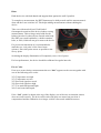
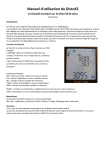
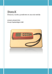
DistoX2 User Manual
Leica Disto X310 based DistoX
Firmware Version 2.4
2015/02/22
Introduction
DistoX is an electronic surveying device for cavers. It consists of a Leica Disto X310 or
E7400x (US version of the X310) distance meter with a built in replacement board. The board
extends the functionality of the Disto by a three axis electronic compass/clinometer and a
Bluetooth connection to enable wireless readout of the results. The three axis compass allows
measurements of arbitrary directions with arbitrary orientations of the device without
degradation of the precision.
Disto Functions
The Disto behaves similarly to the original X310. The
display shows the Azimuth in the first, the inclination in
the second, and the distance in the bottom line. It stores up
to 1000 measurements to be inspected later or transferred
over the Bluetooth connection.
Main Functions:
DIST: power on / start Laser / measure distance
CLR: cancel current operation, switch Laser off
REF ( ): change distance reference
TIMER: start timer (automatic measurement)
MEM ( ): show memory entries
SMART ( ): show extended measurement information (see below)
FUNC: show device information (see below)
Restrictions
The following X310 functions are not available:
Min, Max, Add, Subtract, Area, Volume, Triangle, Stake out, Smart horizontal.
Caution:
There is no automatic recognition of the position of the endpiece. Press the REF and FUNC
keys to switch between rear case and endpiece reference.
Options and Configuration
The following keys and key combinations can be used to change various options when
pressed for 2 seconds.
MEM:
REF:
CLR:
MEM and SMART:
MEM and FUNC:
MEM and MINUS:
REF and MINUS:
REF and PLUS:
REF and FUNC:
CLR and SMART:
CLR and MEM:
CLR and FUNC:
CLR and MINUS:
SMART and MINUS:
change distance unit
switch to permanent front reference
power off
angle unit: degrees/grad
silent mode on/off
backsight mode on/off
beep on/off
display illumination on/off
back reference: case/endpiece
calibration mode on/off
clear unsent memory
Bluetooth on/off
locked power off
triple shot check on/off
The distance and angle units are used for the numbers in the display only; they have no
influence on the stored and transmitted values.
Backsight Mode
If the backsight mode is turned on, the measurements are reported as if they were measured in
the opposite direction. The sign of the inclination is reversed and 180° is added to the
azimuth. On the display a down arrow is shown near the Laser symbol when the option is
turned on and whenever a backsight measured memory value is shown.
Triple Shot Check
If the triple shot check option is turned on, the device checks for three nearly identical
measurements in a row. If a triple is detected the device beeps twice and shows an ‘identical’
sign ( ≡ ) to the right of the measured values. Three shots are considered nearly identical if the
pairwise comparison results in a distance difference < 5cm and a directional difference < 3%
(1.7°). PocketTopo uses the same measure to distinguish survey shots from splay shots. A
small triangle ( ) is shown a in the lower left corner of the display if the check is switched
on.
Factory Reset
Press CLR, FUNC, and MEM for 5 seconds to reset the device to the original state.
The memory is erased completely, the user options are set to default values, and the
calibration coefficients are reset to a neutral calibration. To preserve the calibration, read the
calibration coefficients from the device, reset the device, and write the coefficients back to the
device.
Extended Measurement Information
The SMART key can be used to show extended information about a measurement. Repeated
key presses cycle through the following parts. After the last part, the display returns to the
standard contents.
Normal Measurements:
1) Azimuth, horizontal distance, vertical distance, total distance.
2) Roll angle and dip angle (inclination of the magnetic field).
3) Magnitude of the magnetic field and the acceleration/gravity.
4) Raw sensor values (x,y,z) of the on board acceleration sensor. *)
5) Raw sensor values (x,y,z) of the separate acceleration sensor. *)
6) Raw sensor values (x,y,z) of the magnetic field sensor. *)
Calibration Measurements:
1) Combined acceleration sensor values (x,y,z).
2) Magnetic field sensor values (x,y,z).
3) On board acceleration sensor values (x,y,z). *)
4) Separate acceleration sensor values (x,y,z). *)
*) These parts are not available when reading from memory.
Bluetooth Connection
When Bluetooth is switched on, the device is discoverable and connectable at any time. It
appears as “DistoX-nnnn” where nnnn is the serial number of the device. It provides a serial
connection (SPP) named “serial”. The device needs no pairing key. If the connecting device
request one, it is “0000” (four zeroes).
To read the results from the device, a special program is needed (PocketTopo). This runs
either on a PC or on a PDA. To Allow the program to connect to the Disto, the Bluetooth port
must be selected under Menu:Options:Port. The port is listed in the Bluetooth manager as the
“outgoing serial port” for the device.
When Bluetooth is switched on, a Bluetooth symbol appears at the top of the display. The
symbol flashes whenever another device is connected. Except when a memory entry is shown,
the display shows the number of unsent measurements in the top right corner.
It is possible to switch the Laser on or off over Bluetooth and to remotely trigger a
measurement. The corresponding commands are in the Bluetooth menu.
The Disto does not automatically switch off as long as there is an active Bluetooth
connection.
Silent Mode
In Silent mode the device does not transfer measured data even if a PDA is connected. The
data is still saved to memory but immediately marked as sent. The display shows three dashes
(---) in the top right corner when in Silent Mode. Press MEM and FUNC for 2 seconds to
switch silent mode on and off.
Pressing CLR and MEM for 2 seconds marks all measured data as sent without entering
Silent mode.
Charging the Battery
To charge the battery, a 5V source must be connected to the charging connector in the battery
compartment. Any phone charger with a micro USB connector will do the job.
The battery indicator in the display shows the actual battery level. It flashes when a charger is
connected and stops flashing when the battery is fully charged.
Device Information
The FUNC key can be used to show a sequence of information screens. FUNC key in idle
mode shows the first screen. FUNC again navigates from one screen to the next. Use the
SMART key to return to the previous screen.
Screen 1: Battery
Shows the actual battery voltage and the battery chemistry used for the battery level indicator:
“LI” for LiPo or “AL” for Alkaline.
Press the FUNC and SMART keys for 5 seconds to change the battery chemistry. Be sure to
use the correct setting:
LI (default) for a built in rechargeable battery or AL for AAA primary cells.
Screen 2: Versions
Shows the hardware and firmware version numbers and the serial number of the device.
Screen 3: Display Illumination
Shows the display illumination level (1 - 10).
To change the level first press the PLUS and MINUS keys for 2 seconds to allow editing.
Then press the PLUS or MINUS key to change the value.
To switch the illumination off completely, use REF + PLUS option mentioned above.
Screen 4: Endpiece Offset
Shows the actual endpiece offset in mm (-128 - 127).
To change the level first press the PLUS and MINUS keys for 2 seconds to allow editing.
Then press the PLUS or MINUS key to change the value.
Changing the offset is useful for self-made endpieces or other cases where a non-standard
reference is used.
Hints
Hold the device with both hands and support them against the wall if possible.
To complete a measurement, the DIST button may be held pressed until the measurement is
done and the Laser switches off. This helps making measurements without shaking the
device.
Take care with metal objects! Each kind of
ferromagnetic metal near the device leads to wrong
measurements. This no longer only holds for the
helmet, but also for other objects carried at the body
like SRT gear (steal karabiners), carbide container,
belts, or tools, which all can get to near to the device.
For precise measurements it is recommended to
mark the rear ‘exit point’ of the Laser beam
(picture). Place this point as near as possible to the
survey point.
Switching the display illumination off completely saves a lot of power.
For best performance, the device should be calibrated in regular intervals.
Error Codes
If an error occurs during a measurement the text “Info” appears on the screen together with
one of the following error codes:
252: Temperature too high
253: Temperature too low
255: Received signal too weak
256: Received signal too high
257: Too much background light
260: Laser beam interrupted
If the “2nd” symbol is shown at the top of the display, one of the two acceleration sensors
does not work correctly. The device still works with only one sensor but precision is
compromised and the calibration is no longer valid if it was made with both sensors.
Technical Data
Range
Distance:
Azimuth:
Inclination:
Roll angle:
0.05 – >100m
0 - 360°
-90° - +90° (no steepness limit)
-180° - +180° (fully tilt compensated)
Precision
Distance:
Angles:
2mm (0.05 – 10m)
0.5° RMS (after proper calibration)
Features
Selectable Units: m / ft / inch, ° / grad
Memory capacity: 1000 measurements
Laser Type:
635nm, 1mW, class II
Mechanical
Size:
Weight:
Protection:
55 x 31 x 122mm
150g
IP65
Electrical
Battery voltage:
1.5 – 5.5V
LiPo charger input: 4.5 – 6V
Power consumption
Idle (incl. Bluetooth):
Illumination on:
Laser on:
Bat = 4V:
4mA
9mA
88mA
Bat = 3V:
5mA
11mA
110mA
original X310, Bat = 3V:
36mA
43mA
120mA