1
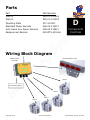
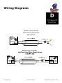
396-001590
Su
re
Fi
re
Ag
Sy
st
em
s
SureFire
Wireless Valve
Controller Manual
Copyright 2012
SureFire Ag Systems
Last Modified: January 16, 2012
Table of Contents
Introduction
st
em
Introduction
• Description of Operation and Capabilities
s
A
Ag
Setup & Operation
• Settings Available
• Calibration
Sy
Components—Electrical
• Part Numbers
Fi
re
Troubleshooting
• Common Problems
D
Components
Electrical
re
F
Su
Setup &
Operation
G
Troubleshooting
Copyright 2012
SureFire Ag Systems
Last Modified: January 16, 2012
General Description
s
A
Introduction
Sy
st
em
The Wireless Valve Controller allows control of up to 4
valves from one remote with one controller and up to 8
valves with one remote with two controller boxes. The
relay output for each channel allows control of one
12VDC device up to 7Amps per channel with a maximum
current for the controller of 10 amps for all of the channels combined.
Basic Setup
Ag
1. Find a location close to the valves you want to control
to mount the Wireless Valve Controller. An angle
mounting plate is available for this purpose
re
2. Use the supplied harnessing to provide power to the
Wireless Valve Controller.
Fi
3. Use the supplied harnessing to hook up the valves to
the Wireless Valve Controller.
Su
re
4. The valve controller and remote come preprogrammed, so unless asked to do so by SureFire Ag
Technicians, no programming is required.
5. With power to the unit, the red light labeled “Power”
should be on. At this point pressing the appropriate
button on the remote will turn on the corresponding
lamp and valve. Pressing the button again will turn
that lamp and output off again.
Copyright 2012
SureFire Ag Systems
Last Modified: January 16, 2012
Parts
Part Number
535-01-100500
535-01-101500
471-2134Y1
208-02-2133Y1
208-02-2136Y1
218-OTX-433-HH
s
D
Components
Electrical
Sy
st
em
Part
WV100
WV101
Mounting Plate
Standard Power Harness
John Deere Aux Power Harness
Replacement Remote
Ag
Wiring Block Diagram
Remote Indicator Panel
Fi
re
Wireless Valve
Controller
re
Valve 1
Su
Fused Power Harness
Valve 2
Valve 3
Valve 4
Copyright 2012
SureFire Ag Systems
Last Modified: January 16, 2012
Wiring Diagrams
s
D
Su
re
Fi
re
Ag
Sy
st
em
Components
Electrical
Copyright 2012
SureFire Ag Systems
Last Modified: January 16, 2012
Wiring Diagrams
s
D
st
em
Components
Electrical
Su
re
Fi
re
Ag
Sy
Wireless Valve Controller
Fused Power Supply Harness
208-02-2133Y1
Copyright 2012
SureFire Ag Systems
Last Modified: January 16, 2012
Operation and Setup
s
Setup &
Operation
st
Procedure for adding remotes
F
em
The Wireless Valve Controller is paired with the remote
at the factory so there is no need to program the remote
out of the box. The following procedure shows the programming for a new remote or for adding a second remote.
Loosen 4
Screws
Sy
1. Unscrew the 4 screws holding the lid on the
enclosure as shown.
Ag
2. Press and RELEASE the learn button shown in
figure 2. The blue “Mode” light will start
flashing. NOTE: if the learn button is held, all
remotes previously programmed may be
erased.
4. Put the cover back on the controller.
Su
re
Fi
re
3. Hold down the 1 button on the new remote
until the blue “Mode” turns solid and the
green 1 light will turn on, on a WV100.
NOTE: You can hold down the 5 button when
programming a WV101 and then the green 5
light will come on when the remote is programmed as verification, but the 1 button
works for programming either model.
Learn Buon
Copyright 2012
SureFire Ag Systems
Last Modified: January 16, 2012
Procedure for resetting all remotes
NOTE: This will erase all previously programmed remotes, so only proceed if that is desired.
s
F
em
Setup &
Operation
st
Loosen 4
Screws
Sy
1. Unscrew the 4 screws holding the lid on the
enclosure as shown.
2. Press and HOLD the learn button shown in
figure 2 until the blue “Mode” light stops
flashing and goes solid.
Su
re
Fi
re
Ag
3. Now follow the programming procedure described earlier in the manual to program the
desired remotes.
Learn Buon
Copyright 2012
SureFire Ag Systems
Last Modified: January 16, 2012
Troubleshooting
RED Power Light Not on:
• Check wiring, and check the inline fuse in the supplied power
cable. Do not use a fuse larger than 10 Amps.
• Check the polarity of the wiring. Refer to electrical section.
s
G
em
Troubleshooting
Su
re
Fi
re
Ag
Sy
st
Remote will not operate valve:
• If there are multiple remotes, make sure you are using
the correct remote.
• Watch the blue “Mode” light as a button is pressed on the remote,
1. If the blue “Mode” light flashes when pressed, then the remote is paired
with the Wireless Valve Controller.
2. If the blue “Mode” light does not flash, need to program remote to be
paired with the Wireless Valve controller. Refer to adding remotes section.
• Do the other valves work?
1. If the other valves are working, is the green light for the valve in question turning on?
• If the green light is turning
on and off, the issue is
most likely a wiring problem between the valve and
the Wireless Valve Controller. Refer to electrical
schematic to check voltages
and wiring.
• If the green light for the
valve in question is not
turning on but the others
are, contact SureFire Ag
Systems.
Power Light
2. If the other valves are not work-
Mode Light
ing, try following the procedure for adding remote, if it
still is not working contact SureFire Ag Systems.
Copyright 2012
SureFire Ag Systems
Last Modified: January 16, 2012
Wireless Valve Controller
MODEL NUMBER:
WV100, WV101
COMPLIANCE TEST REPORT NUMBER:
B11215D1
COMPLIANCE TEST REPORT DATE:
December 15, 2011
RESPONSIBLE PARTY(IN USA):
SureFire Ag Systems
ADDRESS:
9904 Hwy 25
TELEPHONE:
785.626.3670
st
em
TRADE NAME:
s
Declaration of Conformity
Ag
Sy
This equipment has been tested and found to comply with the limits for a Class B digital device, pursuant to Part 15 of the FCC rules. These limits are designed to provide
reasonable protection against harmful interference in a residential installation. This
equipment generates, uses, and can radiate radio frequency energy and, if not installed and used in accordance with the instructions, may cause harmful interference
to radio communications. However, there is no guarantee that interference will not
occur in a particular installation.
Fi
re
If the unit does cause harmful interference to radio or television reception, please refer
to your user’s manual for instructions on correcting the problem.
Signature:
Date: 11/15/2011
Full Name: Albert Popp
Position: Engineer
Su
re
Place: Atwood, Kansas
Copyright 2012
SureFire Ag Systems
Last Modified: January 16, 2012
INSTRUCTION TO THE USER
This equipment has been tested and found to comply with the limits for a class B digital device,
pursuant to part 15 of the FCC Rules. These limits are designed to provide reasonable protection
against harmful interference in a residential installation. This equipment generates, uses and can
radiate radio frequency energy and if not installed and used in accordance with the instructions,
s
may cause harmful interference to radio communications. However, there is no guarantee that
em
interference will not occur in a particular installation. If this equipment does cause harmful
interference to radio or television reception, which can be determined by turning the equipment
off and on, the user is encouraged to try to correct the interference by one or more of the
st
following measures:
Sy
* Reorient or relocate the receiving antenna.
* Increase the separation between the equipment and receiver.
* Connect the equipment into an outlet on a circuit different from that to which the receiver is
connected.
Ag
* Consult the dealer or an experienced radio/TV technician for help.
In order to maintain compliance with FCC regulations, shielded cables must be used with this
equipment. Operation with non-approved equipment or unshielded cables is likely to result in
re
interference to radio and TV reception. The user is cautioned that changes and modifications
made to the equipment without the approval of manufacturer could void the user's authority to
Su
re
Fi
operate this equipment.
Copyright 2012
SureFire Ag Systems
Last Modified: January 16, 2012