1
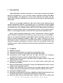
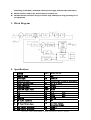
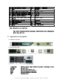
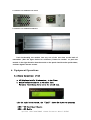
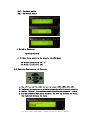
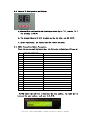
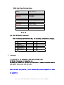
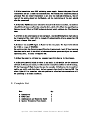
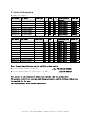
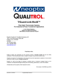
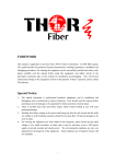
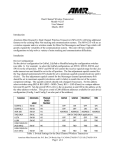
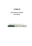
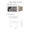
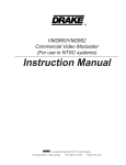
OptiLink Model-M107/M607x 1310nm Optical Transmitter User’s Manual OptiLink Model-M107/M607x 1310nm Transmitter Manual ZATECH 1. Introduction Model M107/M607x modular Transmitter is a new product developed by Shianjin Electronics Equipment Co., Ltd. It consists of M107 (Intelligent Chassis) and M607x Transmitter Module. The Appearance of the chassis features LCD display, thin film switch, finger-mark-free steel plate, and a vivid color, which make the unit look elegant and modern. M107 is a one intelligent standard 19" 1RU chassis. M107 can be monitored by the network management software, even though there is no transmitter module plugged into the chassis. In this way, the network management software can get clear status of the available slots in all intelligent chassis, M107. Except for M607 (Optical Transmitter Module), the other modules such as forward optical receiver, reverse optical receiver, and etc., can be plugged into M107, which offers two respectively independent slots. M607x optical transmitter module has 4 kinds of specification classes, and each class has totally 11 output powers including 2,4,6,8,10,12,13,14,16,18 and 20dBm, . (Refer to the Ordering Information below) M607x optical transmitter module uses an internal isolated Distributed Feedback (DFB) laser, which represents the latest technology. Its high cost-effective and wonderful performance are highlighted by its advanced multipoint pre-distortion correction circuit, RF pre-amplifier circuit, high reliability of power supply, intelligent and efficient element management, and unique airflow design. 2. Features 860MHz bandwidth; High-performance DFB laser to increase the signal quality in HFC; Low noise, low distortion and pre-AMP to meet low RF input signal; Incorporating circuit design built with RF AMP and VCA, and multi-point pre-distortion correction, enhance equipment distortion specification; Separate CPU control board in each OTX module to support effective control and multi-protection function; Effective RF overdrive protection for LD ,low optical power output alarm and automatic LD shutdown; Effective ATC(Automatic Temperature Control) and APC(Automatic Power Control) enable precise optical power levels; Elective AGC (Automatic Gain Control) and field MGC (Manual Gain Control) enables superior link optimization and variable modulation depth (RF drive level); Front panel -20dB RF test port; RS232/485 and RJ45 Ethernet interfaces, SNMP/Telnet /Web IE network protocol can be used to realize local or remote status monitoring and controlling; Advanced high efficiency switching power supply to meet the AC voltage wide OptiLink Model-M107/M607x 1310nm Transmitter Manual ZATECH fluctuating (176V-264V); redundant switch power supply and automatic alternation; Module position swap freely and hot plug-in and pull-out; Reliable thermal structure design to ensure high stability and long operating life of the equipment. 3. Block Diagram 4. Specifications Item 1 2 3 4 5 6 7 8 9 10 11 12 Type of laser Wavelength Modulation mode Output Optical Power Fiber Connector Frequency Range Input RF Signal Level CNR CTB CSO Flatness RF Input Impedance 13 RF Input Return Loss 14 15 APC Control Precision ATC Control Precision Unit nm mw MHz dBuv dB dB dB dB Ω dB dB ℃ Specification DFB 1310±20 Direct Light Intensity Modulation 4 6 8 10 13 16 SC/APC 47-870 80±3 ≥52 Note ≤-67 Note ≤-62 Note ±0.75 75 ≤-16(47-550MHz) ≤-14(551-870MHz) ≤±0.1 25±1 OptiLink Model-M107/M607x 1310nm Transmitter Manual ZATECH 16 17 18 19 20 21 22 23 24 25 26 Max TEC Operating current MTBF Laser Operating Voltage Range Laser Operating Temperature Range Overall Storage Temperature Range Overall Relative Humidity Overall Power Supply Input (with Filter) Communication Interface Power Dissipation Dimensions Weight mA h V ℃ ℃ % V 850@DC+5V, 850@DC-5V ≥40000 DC±4.5--±5.5 +5--+40 -25—55 40—70 AC220(86-264V) W mm Kg RS232/485 50 480x350x44 4 (2 modules) Note: Distortion test condition: 10Km fiber + adjustable optical attenuator, 69207B optical node -1dBm optical power input and test. 5. Appearance description 5.1.Chassis Front Panel: 5.2.Chassis Rear Pannl: ~220V 50Hz RF INPUT OPT OUT RS232 RS485 GND Switching power supply socket with filter (including 1A fuse) RF input port Optical power output port Network Management Interface Network Management Interface Grounding bolt OptiLink Model-M107/M607x 1310nm Transmitter Manual ZATECH 5.3. M607x OTx Module Front Panel: 5.4. M607x OTx Module Installation: Push horizontally the module into any one of the two slots at the back of transmitter. (See the figure below for reference.) Please be careful to push the module in the right direction that the words on the panel should not be upside down, and then tighten the two screws. 6. Equipment Operations: 6.1.Display Explanations of LCD a. LCD displays totally 20 characters, in two lines. b, Module/ Parameter name is in the first line; Parameter value/Alarm status is in the second line. c.At the right bottom of LCD, the “[xxx]” shows the object of operating [1RU]---1RU Intelligent Chassis [MKD]---MKD Module OptiLink Model-M107/M607x 1310nm Transmitter Manual ZATECH [01]---The First module [02]---The Second module d, Switch-on Character: OptiLink Platform e, If there is no module in the chassis, the LCD shows: No Module installed in [01] or No Module installed in [02] 6.2. Operation Explanations of Keyboard: a,The left key and the right key are to select [1RU],[MKD],[01],[02]. b,Top key and bottom key are to select or change the value of present parameter c,The key “Select” is to refresh or modify/confirm the parameter’s value. d, For the parameter that can be modified, the left key increase the value, the right key decrease the value. OptiLink Model-M107/M607x 1310nm Transmitter Manual ZATECH 6.3. Chassis ID Configuration and Diplay: a, Chassis ID is configured by a 8-bits finger switch (up is “1”,down is “0”) The ID range is 00-FF. b, The present Chassis ID will be shown on the two LEDs, use HEX 00-FF. c, After configuring, the chassis must be powered on again. 6.4. M607x Transmitter Module Parameters: Press the top key and the bottom key, the following information will pop up: 0 1 2 3 4 5 6 7 8 9 10 11 12 13 14 15 16 17 OptiLink 1310nm OTx Model Rating LD Power LD Power: LD TEM: LD BIAS: LD TEC: LD Lev: DC +12V: DC +5V: DC -5V: AMP TEM. VCA Offset: Module ID: Software Ver. LD SN: Module SN: Manufacture Date: To VCA Offset the left key to decrease the spar numbers, the right key to increase the spar numbers, each spar is 0.5 dB. OptiLink Model-M107/M607x 1310nm Transmitter Manual ZATECH M607x Module Type Vs Output Power: Model M607X-2 M607X-4 M607X-6 M607X-8 M607X-10 M607X-12 M607X-13 M607X-14 M607X-16 M607X-18 M607X-20 Rating LD Power 2.5mW(4dBm) 4mW(6dBm) 6mW(8dBm) 8mW(9dBm) 10mW(10dBm) 12mW(10.5dBm) 13mW(11dBm) 14mW(11.5dBm) 16mW(12dBm) 18mW(12.5dBm) 20mW(13dBm) X = A,,E 6.5. M107 1RU Chassis Parameters: : Press the top key and the bottom key, the following information will pop up: 0 1 2 3 4 5 OptiLink 1RU Chassis Model: Slot number: Chassis ID: Software Ver.: Chassis SN: M107 2 (DIP state) V1.0 CM107XXX 7. Caution 7.1.Once you get the equipments, check the following items: A) Whether the package is damaged or not. B) Unpack the transmitter, and check the compliance of transmitter module quantity and nominal output power with the order. Once you find any problem, please contact the product supplier as soon as possible. OptiLink Model-M107/M607x 1310nm Transmitter Manual ZATECH 7.2.This transmitter uses 220V switching power supply. Connect the power line of transmitter and put it into the standard rack. The transmitter should be properly grounded. When the indoor transmitter is put into the rack and switched on, the air vent of the module should not be blocked, and the ventilation of the unit should also be guaranteed. 7.3.The fiber FC/APC connector should be cleaned with absolute alcohol, to minimize the additional loss or reflection caused by dust, which will affect the specification. Connect the tail fiber to FC/APC socket on the rear panel, and keep the fiber hanging down. 7.4.Switch on the power supply on the rear panel, and the LCD background light should be illuminated (the light will be turned off automatically after a moment for LCD to have a longer life span). 7.5.Connect the mixed RF signal to F port on the rear panel. The input level should be within a range of 80±3dBuv. On condition that the distortion specification is guaranteed, local RF level setting function can be used in the field of the transmission system to adjust the actual operating level, in order to improve CNR. 7.6.When the power is switched on, company logo will show up in the display. 7.7.The green LED will flash if there is any fault in the Module. If the frequency of flash is 3 times per second, it indicates the transmitter module is out of working; If the frequency of flash is one time per two seconds, it indicates the transmitter module can still work with alarm. And you can get alarm details from the LCD. The alarm light will be turned on when the problem is solved and the transmitter will be operating in a normal condition. 8. Complete List Name Qty a. b. c. d. 1 1 1 1 Transmitter Power-line Installation and Operation Guide Optical Transmitter Test Result OptiLink Model-M107/M607x 1310nm Transmitter Manual ZATECH 9. Order Information ▲ M607x OTx Module: OTx Model Op Power M607A-10 M607A-12 M607A-13 M607A-14 M607A-16 M607A-18 M607A-20 10mW(10dBm) 12mW(10.5dBm) 13mW(11dBm) 14mW(11.5dBm) 16mW(12dBm) 18mW(12.5dBm) 20mW(13dBm) OTx Model Op Power M607E-4 M607E-6 M607E-8 M607E-10 M607E-12 M607E-13 M607E-14 M607E-16 M607E-18 M607E-20 4mW(6dBm) 6mW(8dBm) 8mW(9dBm) 10mW(10dBm) 12mW(10.5dBm) 13mW(11dBm) 14mW(11.5dBm) 16mW(12dBm) 18mW(12.5dBm) 20mW(13dBm) Link Loss Link Loss CNR CSO CTB 54 54 54 54 54 54 54 65 65 65 65 65 65 65 69 69 69 69 69 69 69 CNR CSO CTB 50 50 50 50 50 50 50 50 50 50 60 60 60 60 60 60 60 60 60 60 65 65 65 65 65 65 65 65 65 65 Predistortion Circuit Multi-Point Multi-Point Multi-Point Multi-Point Multi-Point Multi-Point Multi-Point Order PN Predistortion Circuit Multi-Point Multi-Point Multi-Point Multi-Point Multi-Point Multi-Point Multi-Point Multi-Point Multi-Point Multi-Point Order PN 2450124 2450125 2450126 2450127 2450128 2450129 245012A 2450521 2450522 2450523 2450524 2450525 2450526 2450527 2450528 2450529 245052A Note: Product Specifications can be modified without notice ▲ OptiLink Model M607x OTx Module ▲ OptiLink Model M107 19”1RU Chassis(no MKD) order PN 2450120-245052A order PN 2451118 Test report of the transmitter module will include all the models above. The warranty period is one year (man-made damage exclusive), and the lifelong paid service is provided for the user. (The specifications are subject to change without notice.) OptiLink Model-M107/M607x 1310nm Transmitter Manual ZATECH