1
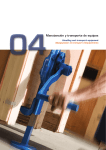
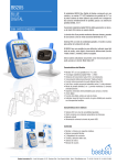
Warning to all users
PORTABLE COLOR
LCD DIGITAL WIRELESS
MONITORING SYSTEM
INSTRUCTION MANUAL
Please read carefully this user manual before using the BB – 201 Blue Digital wireless monitoring system.
Failure to follow these warnings and the assembly instructions could result in serious inquiry or death.
-
-
-
Keep the AC adapter cords out of the reach of children.
Protect the AC adapter cords. Make sure that they are not walked on or pinched by furniture or
other items.
Use ONLY the AC adapters provided in this kit. Using other 3rd parties AC adapters may cause
fatal damage to the monitoring system.
Make sure the provided AC adapters are at the same electrical voltage of your country.
Do not place the monitoring system or its cord within the child reach.
Provide proper ventilation for the monitoring system when it is operating. Do not cover the
Monitor unit and Camera unit with any material, such as a blanket. Do not place the Monitor and
Camera units in a poor ventilation area, such as a drawer.
Do not immerse the monitoring system in water. Clean it only with a dry cloth.
Do not use the monitoring system near any possible wet areas, such as a bathtub, shower, basin,
sink, laundry tub.
Do not use the monitoring system outdoors.
Keep the monitoring system away from heat sources, such as fireplaces, radiators, stove.
Do not attempt to open the Monitor unit, Camera unit and the AC adapters. No user-serviceable
parts inside. Risk of electrical shock, fire or death.
FCC Statement
WARNING : Modifications not authorized by the manufacturer may void users authority to operate
this device.
This equipment has been tested and found to comply with the limits for a Class B digital device, pursuant to
Part 15 of FCC Rules. These limits are designed to provide reasonable protection against harmful
interference in a residential installation. This equipment generates, uses, and can radiate radio frequency
energy and, if not installed and used in accordance with the instructions, may cause harmful interference to
radio communications.
However, there is no guarantee that interference will not occur in a particular installation. If this equipment
does cause harmful interference to radio or television reception, which can be determined by turning the
equipment off and on, the user is encouraged to try to correct the interference by one or more of following
measures:
-
Reorient or relocate the receiving antenna.
Increase the separation between the equipment and receiver.
Connect the equipment into an outlet on a circuit different from that to which the receiver is
connected.
Consult the dealer or an experienced radio/TV technician for help.
This device complies with part 15 of the FCC Rules. Operation is subject to the following two conditions:
MODEL:
BB – 201 Blue Digital
1. This device may not cause harmful interference, and
2. This device must accept any interference received, including interference that may cause
undesired operation.
1. Specification
Content
1.
Specification
1
2.
Part List
a. Monitor Unit
b. Camera Unit
Installation
a. Monitor Unit Installation
b. Camera Unit Installation
Operation
a. Power On / Off
b. Volume Adjustment
c. Brightness Adjustment
d. VOX / Voice Activation Function
e. Night Vision Function
f.
Battery Charging
g. LED Indicators
h. Mounting
i.
Pairing / Adding Camera Unit
Troubleshooting
2
3.
4.
5.
3
4
4
Features :
•
•
•
•
•
•
•
•
Digital 2.4GHz wireless transmission for both video and audio signal
Encrypted data transfer to ensure 100% privacy
Adopting Frequency Hopping (FHSS) technology to switch between different
channels automatically.
Extended transmission distance up to 300m at open area.
Supports up to 4 camera units simultaneously.
Automatic night vision function when operating in dim area.
Remote sound activation (VOX) from camera unit.
Portable monitor unit with Lithium battery and built-in battery charger
Monitor unit
5
Display
5
Audio
2.4” TFT color display at 320x240 resolution
1W
5
Frequency
2400 – 2483 MHz (auto select by Frequency Hopping FHSS)
5
Pairing
Supports 4 camera units simultaneously
Switches
Power
Pairing
Volume +/- (10 steps control)
Brightness +/- (6 steps control)
LEDs
Power (green), Low Battery (flash)
Signal Coverage (blue), poor reception (flash), Battery
Charging (red)
Activation
Both manual or voice triggered (VOX) from camera unit
OSD
Brightness, Volume, Pairing selection
Lithium battery
6V 1A DC adaptor
Multi-purpose stand + belt clip or wall mounted
5
6
6
8
9
Battery
A/C power
Mounting mechanism
Camera unit
CMOS Sensor
1/6” VGA, 640x480
Lens
LED
F/No 1.8, EFL 2.95mm, BFL 2.488mm
8x IR LED
Power
Flipping angle
0 – 90 degree
Swinging angle
+/- 15 degree
Microphone
built in
A/C power
6V 1A DC adaptor
Mounting mechanism
Flatbed or wall mounted
Transmitting Power
16dB
Night vision
1
2. Part List
3. Installation
A. Monitor Unit Installation
A. Monitor Unit
1.
2.
Strape Holder
Antenna
3.
4.
Belt Clip/ Stand
5.
Volume Up
Brightness
Up
Signal LED
Volume Down
Brightness
Down
Power LED
A/C Adaptador
Jack
Chargue LED
6.
As shown in pic. 1, lift the Belt Clip at the back of Monitor Unit, and remove the
battery door.
Insert the Lithium battery in correct direction. Make sure the metal contact of battery
is in touch with the metal contact of battery bay.
Close the battery door.
Charge the battery by using the provided AC adapter. Attach the AC adapter to the
Monitor Unit as shown in pic. 2. Then plug the AC adapter into the wall AC socket.
The battery charging process will start automatically (Charge LED on). For first time
usage, please keep charging the battery for at least 3 hours until the charge LED
goes off.
Press power button to power on the Monitor Unit.
Wall Outlet
Power
Battery
Cover
Pairing
A/C
Adaptador
Pic 1
Pic 2
B. Camera Unit
B. Camera Unit Installation
1.
Antenna
2.
Attached the provided AC adapter to the Camera Unit as shown in pic 3. The power
jack is located at the bottom of the Camera Unit. Plug the AC adapter into the wall
AC socket.
Press ‘Power Button’ to power on the Camera Unit.
Wall Outlet
Lens
Pairing
A/C Adaptador
Jack
A/C
Adaptador
Power
Pic 3
2
3
4. Operation
B. Volume Adjustment
A. Power On / Off
1. To power on the Monitor Unit, press the ‘Power’ button once. The ‘Power’ LED will show
green colour indicating the Monitor Unit is on.
2.To power on the Camera Unit, press the ‘Power’ button once. The green LED will light up
indicating the Camera Unit is on.
By pressing the + / - of ‘VOL’ button at the left side of the Monitor Unit will adjust the sound
volume of the speaker. Press ‘+’ to increase the volume. Press ‘-‘ to reduce the volume. The
screen shows 0 for mute mode, and 9 for loudest.
C. Brightness Adjustment
By pressing the + / - of ‘ ‘ button at the right side of the Monitor Unit will adjust the
brightness of the display. Press ‘+’ to increase the brightness. Press ‘-‘ to reduce the
brightness. The screen shows 0 for dimmest and 5 for brightest.
D. VOX / Voice Activation
pic. 4 shows the opening screen with Basbau Logo.
3.
For power saving purpose, the Monitor Unit will automatically enter Standby mode
after inactivity of 180 seconds (3 mins.), and the screen will show as pic. 5.
VOX is a build in function of BB – 201 Blue Digital system. When the system entered the
standby mode, the screen of Monitoring Unit will turn off for energy saving purpose. At the
same time, VOX will be activated automatically, and detects the sound level nearby the
Camera Unit. Once it reaches the certain level, VOX will awake the Monitoring system from
standby mode.
E. Night Vision
The Camera Unit have build-in 8 pieces of Infra-red LEDs for picking up clear images in dim
area, but not affecting the environmental brightness. When the photo light sensor detects
low ambient light level, the night vision function will turn on automatically.
F. Battery Charging
(pic. 5)
4.
To resume from stand-by mode, press any button except power button, will awake
the system. At the time the system awake, you will see the screen as shown in pic. 6.
The Monitor Unit is equipped a rechargeable Lithium battery for portable use. When the
Power LED (green) is flashing, it indicates the Lithium battery is at low battery level. You are
required to charge your Lithium battery by the provided AC adapter.
Attach the AC adapter to the monitor unit, and plug the AC adapter into the wall AC socket.
(pic. 7) The charging process will start automatically and the Charge LED (red) will light up.
When the Charge LED goes off, it indicates the battery is full, and you can unplug the A/C
adapter from the Monitor Unit.
Wall Outlet
(pic. 6)
5.
(RED)
A/C
Adaptador
To power off the Monitor Unit, press and hold the Power button for 2 sec.
Pic 7
4
5
G. LED Indicators
Camera Unit
Monitor Unit
NOTE : To achieve the best performance of signal transmission, please place the
antenna at a vertical position.
Power
•
•
•
Green light (Power On)
Flashing green light (Low battery)
Off (Power Off)
Signal
•
•
•
Blue light (Good Signal Coverage)
Flashing blue light (Marginal Signal Coverage)
Off (No Signal)
Charge
•
•
Wall Mount
Place 2 screws on the wall at 5.5cm pitch. Hook the camera unit on the screws as
shown in pic. 10. Lift the cover plate to adjust the flipping angle (0-90 degree) or
swinging angle (+/- 15 degree).
Red light (Lithium Battery Charging)
Off (Battery Not Charging)
Camera Unit
Power
•
•
Green light (Power On)
Off (Power Off)
H. Mounting
Pic 10
Monitor Unit
Flat Bed
Belt Clip
Place the Camera Unit on a solid horizontal plane. Lift the cover plate to adjust the
flipping angle (0-90 degree) or swinging angle (+/- 15 degree).
Push belt clip lock and move up
the belt clip to the direction as shown
in pic. 8.
Stand
Push belt clip lock and move down
the belt clip to the direction as shown
in pic. 9.
Lift the belt clip and lock into position.
Pic 11
6
7
9.
I. Pairing / Adding Camera Unit
NOTE : The Monitor Unit and Camera Unit were already paired in manufacturing process. In
general, users are not advised to perform any pairing by their own.
If you have more than 1 Camera Unit to pair, you can repeat the above step with the
next Camera Unit(s) until all of them are correctly paired. If you would like to skip
pairing of particular Camera ID, press ‘P’ button of Monitor Unit once.
Basbau Camera Pairing System
If user have brought another set of BB – 201 Blue Digital wireless monitoring system or BB – 201
Blue Digital Camera unit, you can pair the new Camera Unit by the following procedures. As a
result, the Monitor Unit will support multiple Camera Units simultaneously.
1.
2.
3.
4.
5.
Waiting signal from CAM1 … OK
Power Off all Monitor Unit and Camera Units.
Press and Hold the ‘ P ‘ button of the Monitor Unit.
Press the Power button of the Monitor Unit.
Release both the ‘P’ and Power button.
You will then enter the pairing mode screen as shown below.
Waiting signal from CAM2 … SKIP
Basbau Camera Pairing System
Press 'PAIRING' of Camera Unit to pair
Press 'P' to skip and pair the next CAM ID
Waiting signal from CAM1 …
Press power button to abort and turn off
Press 'PAIRING' of Camera Unit to pair
Press 'P' to skip and pair the next CAM ID
10.
Maximum 4 Camera Units can be paired to the Monitor Unit. The screen will show the
correspondent Camera ID number while pairing.
11.
Press and hold power button for 2 seconds at any time you have finished the pairing
process. You will then shut down the Monitor Unit and new setting will be saved.
Turn on the Monitor Unit again will activate the new setting.
Press power button to abort and turn off
6.
7.
Press ‘POWER’ button of your Camera Unit to power on your Camera Unit(s).
If you have only 1 Camera Unit to pair, press the ‘Pairing’ button on your Camera Unit.
If pairing is success, the screen of your Monitor Unit will show below message.
Basbau Camera Pairing System
5. Trouble Shooting
If you don’t get a screen (Including Basbau Logo) at all,
1.
Waiting signal from CAM1 … OK
2.
Waiting signal from CAM2 …
3.
Press 'PAIRING' of Camera Unit to pair
Make sure both the Camera unit and Monitor unit are turned on. The green Power
LED will light up and indicated the system is on.
If the Power LED (green) is not light up, please check if the A/C adapter is correctly
installed and the wall electrical socket is on. (For trouble shooting purpose, please
connect the Monitor Unit to the A/C adapter, besides of using the internal Lithium
battery.)
If the Power LED (green) is light up, but there is no screen. Pls. remove the battery
and unplug the A/C adapter. Wait for 10 minutes. Plug the A/C adapter back to the
Monitor Unit and retry to power on the Monitor Unit.
Press 'P' to skip and pair the next CAM ID
Press power button to abort and turn off
8.
If you have only 1 Camera Unit to pair, you can now turn off the Monitor Unit by press
and hold Power button for 2 seconds. New setting will be saved. Turn on the Monitor
Unit again will activate the new setting.
8
9
If you have seen the opening screen, but nothing afterwards,
1.
2.
3.
4.
5.
Please check if your Camera unit is turned on. The green Power LED will light up and
indicated the system is on.
Make sure the Camera unit and Monitor Unit are within range of each other. For
trouble shooting purpose, you should remove all the obstacles between two units,
and keep shortest distance. (within 5 meters)
Press the ‘P’ button and scan through 4 pre-set camera ID to make sure your Camera
Unit was not paired to other pre-set ID.
Pls. remove the battery and unplug the A/C adapter. Wait for 10 minutes. Plug the
A/C adapter back to the Monitor Unit and retry to power on the Monitor Unit.
If all above steps fail, you are advised to pair the Monitor Unit and Camera Unit. Pls.
following the steps mentioned in Pairing/Adding Camera Unit.
4.
www.basbau.com/declarationofconformity/1999/5/EC=8437012400009/bb201bluedigital.pdf
Por la presente, Basbau Innovation declara que BB - 201 Blue Digital cumple con los
requisitos esenciales y otras exigencias relevantes de la Directiva 1999/5/CE.
Pueden consultar la declaración de conformidad en:
If the screen displays the below picture,
3.
Basbau Innovation declares that the BB - 201 Blue Digital is in compliance with the
essential requirements and other relevant provisions of Directive 1999/5/EC. This
declaration of conformity may be consulted at:
1.
The Monitor Unit may be out of the
signal coverage from the Camera Unit.
Remove the obstruction or get closer to
the Camera Unit, until the blue LED is on,
will re-gain the signal automatically.
2.
Try to place both antennas vertically. It
gives better effectiveness of signal
transmission.
www.basbau.com/declarationofconformity/1999/5/EC=8437012400009/bb201bluedigital.pdf
Other 2.4GHz or high frequency devices (like WIFI, microwave oven) may interfere
the monitoring system. Turn off these devices will give better performance.
Press the ‘P’ button and scan through 4 pre-set camera ID to make sure your Camera
Unit was not paired to other pre-set ID.
Video problem
1.
2.
Try to adjust the brightness level by pressing the brightness (+/-) button until it gives a
desirable image.
If the colour goes off, it indicates that the Camera Unit is working in a dim area, and
the night vision (Infra-red) function is on.
Sound problem
1.
2.
Try to adjust the volume level by pressing the volume (+/-) button until it gives a
desirable sound level.
If you have heard the shrill sound (feedback), you placed the Monitor Unit and
Camera Unit too close. Place them apart or lower the volume level will solve the
problem.
Do not attempt to open the casing of the system or the battery. Improper use of the system
will cause fatal damage. Moreover, the warranty will be void.
10
11