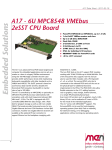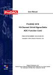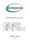
1
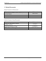
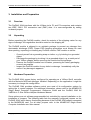
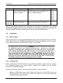
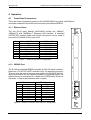
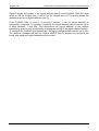
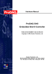
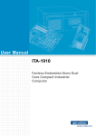
Hardware Manual
ProDAQ 3044
Embedded Slot-0 Controller
PUBLICATION NUMBER: 3044-XX-HM-0100
Copyright, © 2007, Bustec Production, Ltd.
Bustec Production, Ltd.
World Aviation Park, Shannon, Co. Clare, Ireland
Tel: +353 (0) 61 707100, FAX: +353 (0) 61 707106
PROPRIETARY NOTICE
This document and the technical data herein disclosed, are proprietary to Bustec
Production Ltd., and shall not, without express written permission of Bustec
Production Ltd, be used, in whole or in part to solicit quotations from a competitive
source or used for manufacture by anyone other than Bustec Production Ltd. The
information herein has been developed at private expense, and may only be used
for operation and maintenance reference purposes or for purposes of engineering
evaluation and incorporation into technical specifications and other documents,
which specify procurement of products from Bustec Production Ltd. This document
is subject to change without further notification. Bustec Production Ltd. Reserve the
right to change both the hardware and software described herein.
ProDAQ 3044 Embedded Slot-0 Controller Hardware Manual
3044-XX-HM
Table of Contents
1.
OVERVIEW ..................................................................................................................5
2.
RELATED DOCUMENTS.............................................................................................6
3.
INSTALLATION AND PREPARATION........................................................................7
3.1
OVERVIEW...............................................................................................................7
3.2
UNPACKING .............................................................................................................7
3.3
HARDWARE PREPARATION ........................................................................................7
Description....................................................................................................................8
Setting ..........................................................................................................................8
3.4
INSTALLATION ..........................................................................................................8
3.4.1
PMC modules.................................................................................................8
3.4.2
ProDAQ 3044 .................................................................................................8
4.
OPERATION ..............................................................................................................10
FRONT-PANEL CONNECTORS ..................................................................................10
4.1.1 Ethernet Ports ..................................................................................................10
4.1.2
DEBUG Port .................................................................................................10
4.2
FRONT-PANEL INDICATORS .....................................................................................11
4.3
FRONT-PANEL SWITCHES .......................................................................................11
4.4
LOGICAL ADDRESS SWITCH ....................................................................................11
4.1
Copyright, © 2007 Bustec Production Ltd.
Page 3 of 14
3044-XX-HM
ProDAQ 3044 Embedded Slot-0 Controller Hardware Manual
List of Figures
Figure 1 - LAN Connectors Pin Assignment ......................................................................10
Figure 2 - DEBUG Connector and Cable Pin Assignment .................................................10
Figure 3 - Logical Address Switch Location .......................................................................11
Page 4 of 14
Copyright, © 2007 Bustec Production Ltd.
ProDAQ 3044 Embedded Slot-0 Controller Hardware Manual
3044-XX-HM
1. Overview
The ProDAQ 3044 Slot-0 Controller provides a powerful platform for advanced embedded
applications. Using the first VME board designed with the new Tundra Tsi 148 VMEbus
interface, it is the first VXIbus slot-0 controller supporting the 2eVME protocol added in the
VXIbus System Specification 3.0, allowing backplane transfer rates up to a theoretical
maximum of 160 Mbytes/second.
But the MVME6100 series provides more than just faster VMEbus transfer rates; it
provides balanced performance from the processor, memory subsystem, local buses and
I/O subsystems. The processor running at speeds of 1.267 GHz is ideal for data-intensive
applications. The state-of-the-art host bridge, with support for a 133 MHz host bus and a
133 MHz DDR memory bus, is well matched to the processor. To ensure that the
MVME6100 series can handle the 160MB/s data rates of 2eVME, the Tsi148 VMEbus
interface chip is connected to one of the 133 MHz PCI-X buses on the host bridge. The
second PCI-X bus has dual PMC-X sites—each site supports PMC or PMC-X cards
supporting PCI bus speeds from 33 to 100 MHz. The MVME6100 also offers dual Gigabit
Ethernet interfaces. All of this adds up to a set of well-balanced, high-performance
subsystems for unparalleled performance.
The ProDAQ 3040 6U VME64x to C-Size VXIbus Adapter allows the usage of 6U VMEbus
boards in a C-Size VXIbus system. It translates VMEbus cycles into VXIbus cycles and
vice versa. In addition it houses the extensions necessary for VXIbus devices, as there are
the configuration registers, a trigger and extended interrupt interface, MODID support and
the 10 MHz clock generation.
It forwards all VME master cycles transparently to the VXIbus, allowing a VMEbus master
the full access to the VXIbus. On the VXIbus it allows the full integration of the module in
the VXIbus resource management by providing a set of VXIbus compatible configuration
registers and a configurable translation window in the VXIbus A24 or A32 address space.
Accesses to this translation window are forwarded to the VMEbus module’s A16, A24, A32
or CR/CSR space.
Programmable interrupt, trigger and MODID support (both detection and generation), 10
MHz clock generation and auto-Slot0 detection allow the board to be used as an
embedded controller in Slot-0 and non-Slot-0 applications.
Copyright, © 2007 Bustec Production Ltd.
Page 5 of 14
3044-XX-HM
ProDAQ 3044 Embedded Slot-0 Controller Hardware Manual
2. Related Documents
Bustec Production Ltd Documents:
Title
ProDAQ 3040 6U VME64 to C-Size VXI Adapter
Hardware Manual
Motorola Publication Number
3040-XX-HM
Motorola Computer Group Documents:
Title
MVME6100 Single Board Computer
Installation and Use
MVME6100 Single Board Computer
Programmer’s Reference Guide
MOTLoad Firmware Package User’s Manual
Page 6 of 14
Motorola Publication Number
V6100A/IH
V6100A/PG
MOTLOADA/UM
Copyright, © 2007 Bustec Production Ltd.
ProDAQ 3044 Embedded Slot-0 Controller Hardware Manual
3044-XX-HM
3. Installation and Preparation
3.1
Overview
The ProDAQ 3044 interfaces with the VXIbus via its P1 and P2 connectors and contains
two IEEE 1386.1 PCI mezzanine card (PMC) slots. It is user-configurable by setting
on-board jumpers.
3.2
Unpacking
Before unpacking the ProDAQ module, check the exterior of the shipping carton for any
signs of damage. All irregularities should be noted on the shipping bill.
The ProDAQ module is shipped in an antistatic package to prevent any damage from
electrostatic discharge (ESD). Proper ESD handling procedures must always be used
when packing, unpacking or installing any ProDAQ module, PMC module or similar:
Ground yourself via a grounding strap or similar, e.g. by holding to a grounded
object.
Discharge the package by touching it to a grounded object, e.g. a metal part of
your VXIbus chassis, before removing the module from the package.
Remove the ProDAQ module from its carton, preserving the factory packaging
as much as possible.
Inspect the ProDAQ module for any defect or damage. Immediately notify the
carrier if any damage is apparent.
3.3
Hardware Preparation
The ProDAQ 3044 comes factory configured for operating as a VXIbus Slot-0 controller
with the Motorola MOTload debugger installed. Depending on the application it might be
necessary to change this configuration.
The ProDAQ 3044 provides software control over most of its configuration options by
setting bits in control registers. For additional information, please refer to the MVME6100
Single Board Computer Programmer’s Reference Guide and the ProDAQ 3040 6U
VME64x to C-Size VXIbus Adapter Hardware Manual.
Some options are not software-programmable but controlled by manual installation or deinstallation of jumpers. The following table lists the manually configured jumpers on the
ProDAQ 3044, which have a fixed setting because of the ProDAQ 3040 adapter connected
to the MVME6100 card. For all other jumpers refer to the MVME6100 Single Board
Computer Installation and Use manual.
Copyright, © 2007 Bustec Production Ltd.
Page 7 of 14
3044-XX-HM
ProDAQ 3044 Embedded Slot-0 Controller Hardware Manual
Jumper
J30
Description
Front/Rear Ethernet
and Transition Module
Options Header
Setting
Select front panel ethernet (SBC mode
and P2 ethernet not supported on the
3044 !). Default Setting.
J10,
J15–J18,
J25–J28
PMC/SBC Mode
Selection Headers
1-2 on both to select PMC mode (SBC
mode not supported on the 3044 !)
Default
3-13
4-14
5-15
6-16
7-17
8-18
9-19
10-20
1-2
NOTE: The settings described here supersede the settings as described in the manual
MVME6100 Single Board Computer Installation and Use due to special considerations for
using the MVME6100 series board together with the ProDAQ 3040 adapter.
3.4
Installation
3.4.1 PMC modules
PMC modules mount on top of the MVME6100 single board computer part of the ProDAQ
3044. Please refer to the MVME6100 Single Board Computer Installation and Use manual
for the steps necessary to install a PMC module on your board.
NOTE:
The MVME6100 provides two 32/64-bit PCI/PCI-X buses, operating at a maximum
frequency of 100 MHz when configured to PCI-X mode, and run at 33 or 66 MHz
when running conventional PCI mode. PCI bus 1 is connected to the PMC slots 1
and 2. The maximum PCI-X frequency of 100 MHz supported by PCI bus 1 may be
reduced depending on the number and/or type of PMC/PrPMC installed. If PCI bus 1
is set to +5V VIO, it runs at 33MHz. VIO is set by the keying pins (they are both a
keying pin and jumper). Both pins must be set for the same VIO on the PCI-X bus.
The default setting is +5V VIO, selecting PCI mode at 33MHz!
3.4.2 ProDAQ 3044
Before installing the ProDAQ 3044 into your VXIbus mainframe, ensure that the jumpers
are configured properly, any optional PMC modules are installed and the module
enclosure is assembled properly.
Perform the following steps to install the ProDAQ 3044 in your mainframe:
1. Attach an ESD strap to your wrist. Attach the other end of the ESD strap to an
electrical ground. The ESD strap must be secured to your wrist and to ground
throughout the whole procedure.
Page 8 of 14
Copyright, © 2007 Bustec Production Ltd.
ProDAQ 3044 Embedded Slot-0 Controller Hardware Manual
3044-XX-HM
2. If necessary, perform an operating system shutdown on any computer affected by
the installation. Turn the AC or DC power off and remove the AC or DC power lines
from the system. Remove mainframe or system cover(s) as necessary to access
the VXIbus slots.
3. Remove filler panels from the selected slot if necessary. If you intend to use the
ProDAQ 3044 as slot-0 controller, it must occupy the left-most VXIbus slot in the
system (slot “0”). If you do not intend to use it as slot-0 controller, you may install it
into any other free slot in your mainframe.
4. Slide the ProDAQ 3044 into the selected slot. Verify that the module is seated
properly in the P1 and P2 connectors on the backplane. Do not damage or bend
connector pins.
5. Secure the ProDAQ 3044 in the mainframe with the screws in the top and bottom of
its front panel and verify proper contact with the traverse mounting rails.
6. If your mainframe does not have an auto-jumpering feature for the automatic
propagation of the IACK and BG signals, you might need to set or remove jumpers
on the backplane to allow the proper handling of these signal lines. Refer to your
mainframe documentation for more information.
7. If you want to use the factory-installed debugger interactively, connect the terminal
that is to be used as the debugger system console to the DEBUG port on the front
panel of the ProDAQ 3044.
8. Replace mainframe or system cover(s) and cable peripherals to the panel
connectors as required.
9. Reconnect the system to the AC or DC power source and turn the system power
on.
Copyright, © 2007 Bustec Production Ltd.
Page 9 of 14
3044-XX-HM
ProDAQ 3044 Embedded Slot-0 Controller Hardware Manual
4. Operation
4.1
Front-Panel Connectors
There are three connectors located on the ProDAQ 3044 front panel, two Ethernet
connectors labeled LAN1/LAN2 and one serial port labeled DEBUG.
4.1.1 Ethernet Ports
The two RJ-45 ports labeled LAN1/LAN2 provide the 10BaseT,
100BaseTX and 1000Base-T Ethernet LAN interface. A standard
CAT5e/CAT6 network cable with RJ-45 connectors can be used to
connect the ProDAQ 3044 to your LAN.
Pin
1
2
3
4
5
6
7
8
10Base-T/100Base-TX
TD+
TDRD+
AC Terminated
AC Terminated
RDAC Terminated
AC Terminated
1000Base-T
MDIO0_P
MDIO0_N
MDIO1_P
MDIO2_P
MDIO2_N
MDIO1_N
MDIO3_P
MDIO3_N
ProDAQ 3044
P
M
C
2
Figure 1 - LAN Connectors Pin Assignment
4.1.2 DEBUG Port
The RJ-45 port labeled DEBUG provides an RS-232 serial interface,
based on a TL16C550 UART controller chip. It is asynchronous only.
This port may be used to connect a terminal to the ProDAQ 3044 to
serve as a console for the installed firmware or operating system. By
default the port is configured for a baud rate of 9600 baud, 8 bits per
character, 1 stop bit per character and no parity.
ProDAQ 3044
Pin
Assignment
1
DCD
2
RTS
3
GND
4
TXD
5
RXD
6
GND
7
CTS
8
DTR
P
M
C
1
L
A
N
2
DTE (PC etc.)
Pin
DB-9
4
DTR
8
CTS
5
GND
2
RXD
3
TXD
n.c.
7
RTS
1
DCD
L
A
N
1
D
E
B
U
G
ABT
RST
Figure 2 - DEBUG Connector and Cable Pin Assignment
Page 10 of 14
Copyright, © 2007 Bustec Production Ltd.
ProDAQ 3044 Embedded Slot-0 Controller Hardware Manual
4.2
3044-XX-HM
Front-Panel Indicators
The ProDAQ 3044 has two front-panel indicators located in the DEBUG port RJ45 socket:
BFL (yellow) is asserted by the firmware to indicate a configuration problem or
other failure.
CPU (green) is asserted directly by the CPU bus control signals to indicate CPU
activity.
4.3
Front-Panel Switches
The front panel of the ProDAQ 3044 incorporates a dual function toggle switch labelled
ABT/RST. The ABT/RST switch causes an interrupt signal to be generated. This interrupt
is normally used as an “Abort” signal for the processor to abort program execution and
return control to the debugger firmware. If pressed for more then three seconds, the
“Reset” function is selected and all on-board devices are reset. If the board is located in
slot-0 and functions as a slot-0 controller a SYSRESET# signal is generated.
Note: The dual functionality of the Abort/Reset switch depends on the installed firmware. If
a different firmware then the factory installed Motorola MOTload debugger is installed, the
reaction on the ABT/RST switch depends on this firmware.
4.4
Logical Address Switch
The ProDAQ 3044 Slot-0 Controller can operate as either a Slot-0 controller or as an
embedded VXIbus controller (non-Slot-0). When the ProDAQ 3044 is operated as the
Slot-0 controller, it must be located in the left-most slot (slot “0“) of a VXIbus System
Specification Rev 1.3 (or higher) compatible VXIbus mainframe and be set for logical
address zero (0). If the ProDAQ 3044 is operated as an embedded VXIbus controller
(non-Slot-0), it may be located in any other slot and the logical address can be set to any
value between 1 and 255.
LSB
MSB
1
2
3
4
5
6
7
8
Off
On
Figure 3 - Logical Address Switch Location
Copyright, © 2007 Bustec Production Ltd.
Page 11 of 14
3044-XX-HM
ProDAQ 3044 Embedded Slot-0 Controller Hardware Manual
Figure 3 shows the location of the logical address switch on the ProDAQ 3044. Set each
switch to ‘Off’ for a logical one (1) and to ‘On’ for a logical zero (0). The picture shows the
address switch set to logical address zero (0).
If the ProDAQ 3044 is used in a non-slot-0 position, it can be either statically or
dynamically configured. To configure it statically, the logical address switch must be set to
a value between 1 and 254. This determines the logical address of the module
permanently and can only be altered by changing the setting of the logical address switch.
To configure the ProDAQ 3044 dynamically, the logical address switch must be set to 255.
The resource manager will use the VXIbus MODID lines to access and configure the
board, and assigns a logical address during run-time.
Page 12 of 14
Copyright, © 2007 Bustec Production Ltd.
Bustec Production, Ltd.
World Aviation Park, Shannon, Co. Clare, Ireland
Tel: +353 (0) 61 707100, FAX: +353 (0) 61 707106
Bustec, Inc.
35486 Lorain Road, North Ridgeville, OH 44039, U.S.A
Tel. +1 440 327 8930, Fax: +1 440 327 8982