1
To our customers,
Old Company Name in Catalogs and Other Documents
On April 1st, 2010, NEC Electronics Corporation merged with Renesas Technology
Corporation, and Renesas Electronics Corporation took over all the business of both
companies. Therefore, although the old company name remains in this document, it is a valid
Renesas Electronics document. We appreciate your understanding.
Renesas Electronics website: http://www.renesas.com
April 1st, 2010
Renesas Electronics Corporation
Issued by: Renesas Electronics Corporation (http://www.renesas.com)
Send any inquiries to http://www.renesas.com/inquiry.
Notice
1.
2.
3.
4.
5.
6.
7.
All information included in this document is current as of the date this document is issued. Such information, however, is
subject to change without any prior notice. Before purchasing or using any Renesas Electronics products listed herein, please
confirm the latest product information with a Renesas Electronics sales office. Also, please pay regular and careful attention to
additional and different information to be disclosed by Renesas Electronics such as that disclosed through our website.
Renesas Electronics does not assume any liability for infringement of patents, copyrights, or other intellectual property rights
of third parties by or arising from the use of Renesas Electronics products or technical information described in this document.
No license, express, implied or otherwise, is granted hereby under any patents, copyrights or other intellectual property rights
of Renesas Electronics or others.
You should not alter, modify, copy, or otherwise misappropriate any Renesas Electronics product, whether in whole or in part.
Descriptions of circuits, software and other related information in this document are provided only to illustrate the operation of
semiconductor products and application examples. You are fully responsible for the incorporation of these circuits, software,
and information in the design of your equipment. Renesas Electronics assumes no responsibility for any losses incurred by
you or third parties arising from the use of these circuits, software, or information.
When exporting the products or technology described in this document, you should comply with the applicable export control
laws and regulations and follow the procedures required by such laws and regulations. You should not use Renesas
Electronics products or the technology described in this document for any purpose relating to military applications or use by
the military, including but not limited to the development of weapons of mass destruction. Renesas Electronics products and
technology may not be used for or incorporated into any products or systems whose manufacture, use, or sale is prohibited
under any applicable domestic or foreign laws or regulations.
Renesas Electronics has used reasonable care in preparing the information included in this document, but Renesas Electronics
does not warrant that such information is error free. Renesas Electronics assumes no liability whatsoever for any damages
incurred by you resulting from errors in or omissions from the information included herein.
Renesas Electronics products are classified according to the following three quality grades: “Standard”, “High Quality”, and
“Specific”. The recommended applications for each Renesas Electronics product depends on the product’s quality grade, as
indicated below. You must check the quality grade of each Renesas Electronics product before using it in a particular
application. You may not use any Renesas Electronics product for any application categorized as “Specific” without the prior
written consent of Renesas Electronics. Further, you may not use any Renesas Electronics product for any application for
which it is not intended without the prior written consent of Renesas Electronics. Renesas Electronics shall not be in any way
liable for any damages or losses incurred by you or third parties arising from the use of any Renesas Electronics product for an
application categorized as “Specific” or for which the product is not intended where you have failed to obtain the prior written
consent of Renesas Electronics. The quality grade of each Renesas Electronics product is “Standard” unless otherwise
expressly specified in a Renesas Electronics data sheets or data books, etc.
“Standard”:
8.
9.
10.
11.
12.
Computers; office equipment; communications equipment; test and measurement equipment; audio and visual
equipment; home electronic appliances; machine tools; personal electronic equipment; and industrial robots.
“High Quality”: Transportation equipment (automobiles, trains, ships, etc.); traffic control systems; anti-disaster systems; anticrime systems; safety equipment; and medical equipment not specifically designed for life support.
“Specific”:
Aircraft; aerospace equipment; submersible repeaters; nuclear reactor control systems; medical equipment or
systems for life support (e.g. artificial life support devices or systems), surgical implantations, or healthcare
intervention (e.g. excision, etc.), and any other applications or purposes that pose a direct threat to human life.
You should use the Renesas Electronics products described in this document within the range specified by Renesas Electronics,
especially with respect to the maximum rating, operating supply voltage range, movement power voltage range, heat radiation
characteristics, installation and other product characteristics. Renesas Electronics shall have no liability for malfunctions or
damages arising out of the use of Renesas Electronics products beyond such specified ranges.
Although Renesas Electronics endeavors to improve the quality and reliability of its products, semiconductor products have
specific characteristics such as the occurrence of failure at a certain rate and malfunctions under certain use conditions. Further,
Renesas Electronics products are not subject to radiation resistance design. Please be sure to implement safety measures to
guard them against the possibility of physical injury, and injury or damage caused by fire in the event of the failure of a
Renesas Electronics product, such as safety design for hardware and software including but not limited to redundancy, fire
control and malfunction prevention, appropriate treatment for aging degradation or any other appropriate measures. Because
the evaluation of microcomputer software alone is very difficult, please evaluate the safety of the final products or system
manufactured by you.
Please contact a Renesas Electronics sales office for details as to environmental matters such as the environmental
compatibility of each Renesas Electronics product. Please use Renesas Electronics products in compliance with all applicable
laws and regulations that regulate the inclusion or use of controlled substances, including without limitation, the EU RoHS
Directive. Renesas Electronics assumes no liability for damages or losses occurring as a result of your noncompliance with
applicable laws and regulations.
This document may not be reproduced or duplicated, in any form, in whole or in part, without prior written consent of Renesas
Electronics.
Please contact a Renesas Electronics sales office if you have any questions regarding the information contained in this
document or Renesas Electronics products, or if you have any other inquiries.
(Note 1) “Renesas Electronics” as used in this document means Renesas Electronics Corporation and also includes its majorityowned subsidiaries.
(Note 2) “Renesas Electronics product(s)” means any product developed or manufactured by or for Renesas Electronics.
User’s Manual
RA78K0 Ver. 3.80
Assembler Package
Operation
Target Devices
78K0 Series
Document No. U17199EJ1V0UM00 (1st edition)
Date Published February 2005 CP(K)
© NEC Electronics Corporation 2005
Printed in Japan
[MEMO]
2
User’s Manual U17199EJ1V0UM
Windows and Windows NT are either registered trademarks or trademarks of Microsoft Corporation in the
United States and/or other countries.
UNIX is a registered trademark in the United States and other countries, licensed exclusively though
X/Open Company Ltd.
i386 is a trademark of Intel Corporation.
PC/AT is a trademark of International Business Machines Corporation.
HP9000 Series 700 and HP-UX are trademarks of Hewlett-Packard Inc.
SPARCstation is a trademark of SPARC International, Inc.
Solaris and SunOS are trademarks of Sun Microsystems, Inc.
• The information in this document is current as of February, 2005. The information is subject to
change without notice. For actual design-in, refer to the latest publications of NEC Electronics data
sheets or data books, etc., for the most up-to-date specifications of NEC Electronics products. Not
all products and/or types are available in every country. Please check with an NEC Electronics sales
representative for availability and additional information.
• No part of this document may be copied or reproduced in any form or by any means without the prior
written consent of NEC Electronics. NEC Electronics assumes no responsibility for any errors that may
appear in this document.
• NEC Electronics does not assume any liability for infringement of patents, copyrights or other intellectual
property rights of third parties by or arising from the use of NEC Electronics products listed in this document
or any other liability arising from the use of such products. No license, express, implied or otherwise, is
granted under any patents, copyrights or other intellectual property rights of NEC Electronics or others.
• Descriptions of circuits, software and other related information in this document are provided for illustrative
purposes in semiconductor product operation and application examples. The incorporation of these
circuits, software and information in the design of a customer's equipment shall be done under the full
responsibility of the customer. NEC Electronics assumes no responsibility for any losses incurred by
customers or third parties arising from the use of these circuits, software and information.
• While NEC Electronics endeavors to enhance the quality, reliability and safety of NEC Electronics products,
customers agree and acknowledge that the possibility of defects thereof cannot be eliminated entirely. To
minimize risks of damage to property or injury (including death) to persons arising from defects in NEC
Electronics products, customers must incorporate sufficient safety measures in their design, such as
redundancy, fire-containment and anti-failure features.
• NEC Electronics products are classified into the following three quality grades: "Standard", "Special" and
"Specific".
The "Specific" quality grade applies only to NEC Electronics products developed based on a customerdesignated "quality assurance program" for a specific application. The recommended applications of an NEC
Electronics product depend on its quality grade, as indicated below. Customers must check the quality grade of
each NEC Electronics product before using it in a particular application.
"Standard": Computers, office equipment, communications equipment, test and measurement equipment, audio
and visual equipment, home electronic appliances, machine tools, personal electronic equipment
and industrial robots.
"Special": Transportation equipment (automobiles, trains, ships, etc.), traffic control systems, anti-disaster
systems, anti-crime systems, safety equipment and medical equipment (not specifically designed
for life support).
"Specific": Aircraft, aerospace equipment, submersible repeaters, nuclear reactor control systems, life
support systems and medical equipment for life support, etc.
The quality grade of NEC Electronics products is "Standard" unless otherwise expressly specified in NEC
Electronics data sheets or data books, etc. If customers wish to use NEC Electronics products in applications
not intended by NEC Electronics, they must contact an NEC Electronics sales representative in advance to
determine NEC Electronics' willingness to support a given application.
(Note)
(1) "NEC Electronics" as used in this statement means NEC Electronics Corporation and also includes its
majority-owned subsidiaries.
(2) "NEC Electronics products" means any product developed or manufactured by or for NEC Electronics (as
defined above).
M8E 02. 11-1
User’s Manual U17199EJ1V0UM
3
Regional Information
Some information contained in this document may vary from country to country. Before using any NEC
Electronics product in your application, pIease contact the NEC Electronics office in your country to
obtain a list of authorized representatives and distributors. They will verify:
•
Device availability
•
Ordering information
•
Product release schedule
•
Availability of related technical literature
•
Development environment specifications (for example, specifications for third-party tools and
components, host computers, power plugs, AC supply voltages, and so forth)
•
Network requirements
In addition, trademarks, registered trademarks, export restrictions, and other legal issues may also vary
from country to country.
[GLOBAL SUPPORT]
http://www.necel.com/en/support/support.html
NEC Electronics America, Inc. (U.S.)
NEC Electronics (Europe) GmbH
NEC Electronics Hong Kong Ltd.
Santa Clara, California
Tel: 408-588-6000
800-366-9782
Duesseldorf, Germany
Tel: 0211-65030
Hong Kong
Tel: 2886-9318
• Sucursal en España
Madrid, Spain
Tel: 091-504 27 87
• Succursale Française
Vélizy-Villacoublay, France
Tel: 01-30-67 58 00
• Filiale Italiana
Milano, Italy
Tel: 02-66 75 41
• Branch The Netherlands
Eindhoven, The Netherlands
Tel: 040-244 58 45
• Tyskland Filial
NEC Electronics Hong Kong Ltd.
Seoul Branch
Seoul, Korea
Tel: 02-558-3737
NEC Electronics Shanghai Ltd.
Shanghai, P.R. China
Tel: 021-5888-5400
NEC Electronics Taiwan Ltd.
Taipei, Taiwan
Tel: 02-2719-2377
NEC Electronics Singapore Pte. Ltd.
Novena Square, Singapore
Tel: 6253-8311
Taeby, Sweden
Tel: 08-63 80 820
• United Kingdom Branch
Milton Keynes, UK
Tel: 01908-691-133
J04.1
4
User’s Manual U17199EJ1V0UM
INTRODUCTION
This manual is intended to give users who wish to develop software using the RA78K0 an understanding of the
functions of each program in the RA78K0 Series Assembler Package (hereafter referred to as "the RA78K0") and
of the correct methods of using the package.
This manual does not cover the expressions of directives and source programs or language used in the RA78K0.
Therefore, before reading this manual, read the RA78K0 Series Assembler Package Language User's Manual
(U17198E) (hereinafter referred to as "the Language Manual").
The contents of this manual are intended for use with Ver. 3.80 or later of the RA78K0.
[Target Readers]
The RA78K0 is intended for users who understand the functions and instructions of the microcontroller for which
software is being developed (78K0 Series).
[Organization]
This manual consists of the following eleven chapters and appendixes:
CHAPTER 1
GENERAL
Outlines the role of the RA78K0 in microcontroller software development and the features of the
RA78K0.
CHAPTER 2
PRODUCT OUTLINE AND INSTALLATION
Explains the program file names and operating environment provided by the RA78K0.
CHAPTER 3
EXECUTION PROCEDURE OF RA78K0
Explains the procedure for developing software, using a sample program.
The purpose of this chapter is to provide an opportunity for actual use of each program. Those
who wish to experience operating the RA78K0 should read this chapter.
CHAPTER 4
STRUCTURED ASSEMBLER PREPROCESSOR
CHAPTER 5
ASSEMBLER
CHAPTER 6
LINKER
CHAPTER 7
OBJECT CONVERTER
CHAPTER 8
LIBRARIAN
CHAPTER 9
LIST CONVERTER
CHAPTER 10 PROGRAM OUTPUT LIST
Explains the formats of the lists output by each program.
CHAPTER 11 EFFICIENT USE OF RA78K0
Introduces some measures for optimum utilization of the RA78K0.
CHAPTER 12 ERROR MESSAGES
Explains the error messages output by each program.
APPENDIXES Introduce a list of program options, a list of sample programs, and a list of notices on using the
RA78K0.
The instruction sets are not detailed in this manual. For these instructions, refer to the user's manual of the
microcontroller for which software is being developed.
User’s Manual U17199EJ1V0UM
5
[How to Read This Manual]
Those using an assembler for the first time are encouraged to read from CHAPTER 1 GENERAL of this manual.
Those who have a general understanding of assembler programs may skip this chapter.
Before using the RA78K0, read CHAPTER 3 EXECUTION PROCEDURE OF RA78K0.
After you have become familiar with the operation of each program, you can proceed to utilize the lists in the
APPENDIXES.
[Caution]
In this manual, it is assumed that a PC-9800 Series personal computer or an IBM PC/ATTM compatible is used as
the host machine.
When the HP9000 Series 700TM or SPARCstationTM family is used, keep the following
differences in mind.
•
File name format is different.
- Extension .exe of an executable file is not suffixed with an EWS version such as the HP9000 Series 700.
- Extension .bat of a batch file is rendered .sh with an EWS version such as the HP9000 Series 700.
- The file names shown in uppercase are in lowercase with an EWS version such as the HP9000 Series 700.
•
The execution examples and the environment set-up indicated in this manual differ.
[Conventions]
…
The following symbols and abbreviations are used throughout this manual:
:
Indicates that the same expression is repeated.
[ ]:
Item(s) in brackets can be omitted.
' ':
Characters enclosed in ' ' (quotation marks) will be listed as they appear.
< >:
Names of dialog boxes and Windows
" ":
Characters enclosed in " " (double quotation marks) are titles of chapters,
paragraphs, sections, diagrams or tables to which the reader is asked to refer.
6
___:
Indicates an important point, or characters that are to be input in a usage example.
:
Indicates one blank space.
∆:
Indicates one or more blank or TAB.
∇:
Indicates zero or more blanks or TABs (i.e. blanks may be omitted).
/:
Indicates a break between characters.
~:
Indicates continuity.
[↵]:
Indicates pressing of the Return key.
Note:
Indicates a footnote for item marked with Note in the text.
Caution:
Indicates information requiring particular attention.
Remark:
Indicates supplementary information.
User’s Manual U17199EJ1V0UM
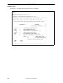
[Related Documents]
The documents related to this manual are listed below.
The related documents indicated in this publication may include preliminary versions.
However, preliminary
versions are not marked as such.
Document related to development tools (user’s manuals)
Document Name
RA78K0 Ver. 3.80 Assembler Package
Document No.
Operation
This manual
Language
U17198E
Structured Assembly Language
U17197E
CC78K0 Ver. 3.70 C Compiler
Operation
U17201E
Language
U17200E
SM+ System Simulator
Operation
U17246E
User Open Interface
U17247E
SM78K0 Series Ver. 2.52 System Simulator
Operation
PM plus Ver. 5.20
U16768E
U16934E
ID78K0-NS Ver. 2.52 Integrated Debugger
Operation
U16488E
ID78K0-QB Ver .2.81 Integrated Debugger
Operation
U16996E
78K0 Series
Instruction
U12326E
Caution
The related documents listed above are subject to change without notice. Be sure to use the
latest version of each document for designing.
User’s Manual U17199EJ1V0UM
7
[MEMO]
8
User’s Manual U17199EJ1V0UM
CONTENTS
CHAPTER 1 GENERAL ... 17
1.1 Assembler Overview ... 17
1.1.1 What is an assembler? ... 18
1.1.2 Development process and RA78K0 ... 19
1.1.3 What is a relocatable assembler? ... 22
1.1.4 Advantages of a relocatable assembler ... 22
1.2 Overview of Features of RA78K0 ... 24
1.2.1 Creating a source module file using an editor ... 25
1.2.2 Structured assembler preprocessor ... 26
1.2.3 Assembler ... 27
1.2.4 Linker ... 28
1.2.5 Object converter ... 29
1.2.6 Librarian ... 30
1.2.7 List converter ... 31
1.2.8 Debugger ... 32
1.3 Reminders Before Program Development ... 33
1.3.1 Maximum performance of RA78K0 ... 33
1.4 Features of RA78K0 ... 36
CHAPTER 2 PRODUCT OUTLINE AND INSTALLATION ... 37
2.1 Host Machine and Supply Medium ... 37
2.2 Installation ... 38
2.2.1 Installation of Windows version ... 38
2.2.2 Installation of UNIX version ... 39
2.3 Installation of Device Files ... 40
2.3.1 Installation of Windows version ... 40
2.3.2 Installation of UNIX version ... 40
2.3.3 Registry registration of device files ... 40
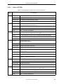
2.4 Directory Configuration ... 41
2.4.1 Windows version directory configuration ... 41
2.4.2 UNIX version directory configuration ... 42
2.5 Uninstallation Procedure ... 43
2.5.1 Uninstallation of Windows version ... 43
2.5.2 Uninstallation of UNIX version ... 43
2.6 Environment Settings ... 44
2.6.1 Host machine (IBM PC/AT compatibles) ... 44
2.6.2 Environmental variables ... 44
2.6.3 Kanji code in source file ... 45
CHAPTER 3 EXECUTION PROCEDURE OF RA78K0 ... 46
3.1 Before Executing RA78K0 ... 46
3.1.1 Sample programs ... 46
3.1.2 Configuration of sample program ... 49
3.2 Execution Procedure of RA78K0 ... 50
3.3 Execution Procedure of ST78K0 ... 56
3.4 Assembling, Linking and Object Conversion from Command Line (DOS Prompt, UNIX) ... 62
3.5 Using Parameter File ... 66
CHAPTER 4 STRUCTURED ASSEMBLER PREPROCESSOR ... 67
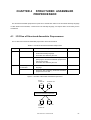
4.1 I/O Files of Structured Assembler Preprocessor ... 67
4.2 Functions of Structured Assembler Preprocessor ... 68
4.3 Structured Assembler Preprocessor Startup ... 69
4.3.1 Structured assembler preprocessor startup ... 69
4.3.2 Execution start and end messages ... 71
4.4 Structured Assembler Options ... 73
User’s Manual U17199EJ1V0UM
9
4.4.1 Types of structured assembler options ... 73
4.4.2 Explanation of structured assembler options ... 73
4.5 Option Settings from PM plus ... 88
4.5.1 Setting options ... 88
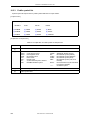
4.5.2 Options ... 90
4.5.3 Edit option dialog box ... 92
CHAPTER 5 ASSEMBLER ... 93
5.1 I/O Files of Assembler ... 93
5.2 Functions of Assembler ... 95
5.3 Assembler Startup ... 96
5.3.1 Command-line startup ... 96
5.3.2 Startup from a parameter file ... 97
5.3.3 Execution start and end messages ... 98
5.4 Assembler Options ... 100
5.4.1 Types of assembler options ... 100
5.4.2 Order of precedence of assembler options ... 102
5.4.3 Explanation of assembler options ... 103
5.5 Options Settings in PM plus ... 140
5.5.1 Option setting method ... 140
5.5.2 Option settings ... 142
5.5.3 Edit option dialog box ... 145
CHAPTER 6 LINKER ... 146
6.1 I/O Files of Linker ... 146
6.2 Functions of Linker ... 147
6.3 Memory Spaces and Memory Areas ... 148
6.4 Link Directives ... 149
6.4.1 Directive files ... 149
6.4.2 Memory directives ... 151
6.4.3 Segment location directives ... 153
6.5 Linker Startup ... 156
6.5.1 Linker startup ... 156
6.5.2 Execution start and end messages ... 157
6.6 Linker Options ... 159
6.6.1 Types of linker options ... 159
6.6.2 Order of precedence of linker options ... 161
6.6.3 Explanation of linker options ... 161
6.7 Option Settings in PM plus ... 194
6.7.1 Option setting method ... 194
6.7.2 Option settings ... 197
6.7.3 Edit option dialog box ... 200
CHAPTER 7 OBJECT CONVERTER ... 201
7.1 I/O Files of Object Converter ... 201
7.2 Functions of Object Converter ... 203
7.2.1 How the object converter handles extended space ... 203
7.2.2 Flash ROM self-rewriting mode support ... 203
7.2.3 HEX-format object module files ... 204
7.2.4 Symbol table file ... 216
7.3 Object Converter Startup ... 218
7.3.1 Object converter startup ... 218
7.3.2 Execution start and end messages ... 219
7.4 Object Converter Options ... 221
7.4.1 Types of object converter options ... 221
7.4.2 Explanation of object converter options ... 222
7.5 Option Settings in PM plus ... 237
7.5.1 Option setting method ... 237
7.5.2 Option settings ... 239
CHAPTER 8 LIBRARIAN ... 241
8.1 I/O Files of Librarian ... 241
8.2 Functions of Librarian ... 243
10
User’s Manual U17199EJ1V0UM
8.3 Librarian Startup ... 245
8.3.1 Librarian startup ... 245
8.3.2 Execution start and end messages ... 248
8.4 Librarian Options ... 249
8.4.1 Types of librarian options ... 249
8.4.2 Explanation of librarian options ... 249
8.5 Subcommands ... 257
8.5.1 Types of subcommands ... 257
8.5.2 Explanation of subcommands ... 257
8.6 Option Settings in PM plus ... 268
8.6.1 Option setting method ... 268
8.6.2 Option settings ... 270
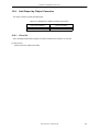
8.7 Method for Manipulating Library Files from PM plus ... 272
8.7.1 Method for manipulating ... 272
8.7.2 Item settings ... 273
CHAPTER 9 LIST CONVERTER ... 275
9.1 I/O Files of List Converter ... 275
9.2 Functions of List Converter ... 277
9.3 List Converter Startup ... 280
9.3.1 List converter startup ... 280
9.3.2 Execution start and end messages ... 282
9.4 List Converter Options ... 283
9.4.1 Types of list converter options ... 283
9.4.2 Explanation of list converter options ... 283
9.5 Option Settings in PM plus ... 291
9.5.1 Option setting method ... 291
9.5.2 Option settings ... 293
CHAPTER 10 PROGRAM OUTPUT LIST ... 294
10.1 Lists Output by Structured Assembler Preprocessor ... 294
10.1.1 Error list ... 295
10.2 Lists Output by Assembler ... 296
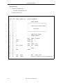
10.2.1 Assemble list file headers ... 297
10.2.2 Assemble list ... 298
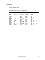
10.2.3 Symbol list ... 300
10.2.4 Cross-reference list ... 301
10.2.5 Error list ... 303
10.3 Lists Output by Linker ... 304
10.3.1 Link list file headers ... 304
10.3.2 Map list ... 306
10.3.3 Public symbol list ... 308
10.3.4 Local symbol list ... 309
10.3.5 Error list ... 310
10.4 List Output by Object Converter ... 311
10.4.1 Error list ... 311
10.5 List Output by Librarian ... 312
10.5.1 Library data output list ... 312
10.6 Lists Output by List Converter ... 313
10.6.1 Absolute assemble list ... 313
10.6.2 Error list ... 313
CHAPTER 11 EFFICIENT USE OF RA78K0 ... 314
11.1 Improving Operating Efficiency (EXIT Status Function) ... 314
11.2 Preparing Development Environment (Environmental Variables) ... 316
11.3 Interrupting Program Execution ... 317
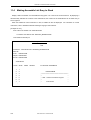
11.4 Making Assemble List Easy to Read ... 318
11.5 Reducing Program Startup Time ... 319
11.5.1 Specifying control instruction in the source program ... 319
11.5.2 Using PM plus ... 319
11.5.3 Creating parameter files and subcommand files ... 320
11.6 Object Module Library Formation ... 321
User’s Manual U17199EJ1V0UM
11
CHAPTER 12 ERROR MESSAGES ... 322
12.1 Overview of Error Messages ... 322
12.2 Structured Assembler Preprocessor Error Messages ... 323
12.3 Assembler Error Messages ... 329
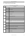
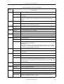
12.4 Linker Error Messages ... 340
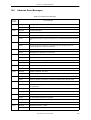
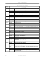
12.5 Object Converter Error Messages ... 349
12.6 Librarian Error Messages ... 353
12.7 List Converter Error Messages ... 357
12.8 PM plus Error Messages ... 361
12.8.1 Structured Assembler Preprocessor (ST78K0) ... 361
12.8.2 Assembler (RA78K0) ... 364
12.8.3 Linker (LK78K0) ... 367
12.8.4 Object Converter (OC78K0) ... 370
12.8.5 Librarian (LB78K0) ... 371
12.8.6 List Converter (LCNV78K0) ... 372
APPENDIX A SAMPLE PROGRAMS ... 373
A.1 k0main.asm ... 374
A.2 k0sub.asm ... 375
A.3 test1.s ... 376
A.4 test2.s ... 377
A.5 testinc.s ... 378
A.6 st.bat ... 379
APPENDIX B NOTES ON USE ... 380
APPENDIX C LIST OF OPTIONS ... 385
C.1 Structured Assembler Options ... 385
C.2 Assembler Options ... 387
C.3 List of Linker Options ... 390
C.4 List of Object Converter Options ... 393
C.5 List of Librarian Options ... 395
C.6 List of List Converter Options ... 396
APPENDIX D LIST OF SUBCOMMANDS ... 397
APPENDIX E INDEX ... 398
12
User’s Manual U17199EJ1V0UM
LIST OF FIGURES
Figure No. Title , Page
1-1
1-2
1-3
1-4
1-5
1-6
1-7
1-8
1-9
1-10
1-11
1-12
1-13
1-14
1-15
1-16
2-1
2-2
3-1
3-2
3-3
3-4
3-5
4-1
4-2
4-3
4-4
4-5
4-6
5-1
5-2
5-3
5-4
5-5
5-6
6-1
6-2
6-3
6-4
6-5
6-6
6-7
6-8
7-1
7-2
7-3
7-4
7-5
7-6
7-7
7-8
8-1
8-2
8-3
RA78K0 Assembler Package ... 17
Flow of Assembler ... 18
Development Process of Microcontroller-Applied Products ... 19
Software Development Process ... 20
RA78K0 Assembly Process ... 21
Reassembly for Debugging ... 23
Program Development Using Existing Module ... 23
Procedure for Program Development Using RA78K0 ... 24
Creating Source Module File ... 25
Function of Structured Assembler Preprocessor ... 26
Function of Assembler ... 27
Function of Linker ... 28
Function of Object Converter ... 29
Function of Librarian ... 30
Function of List Converter ... 31
Function of Debugger ... 32
Directory Configuration ... 41
Directory Configuration ... 42
Structure of Sample Program ... 46
RA78K0 Execution Procedure 1 ... 54
RA78K0 Execution Procedure 2 ... 55
ST78K0 Execution Procedure ... 61
Link Directive ... 63
I/O Files of Structured Assembler Preprocessor ... 67
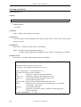
< Structured Assembler Options > Dialog Box (When << Output >> Tab Is Selected) ... 88
< Assembler Source Options > Dialog Box (When [ Assembler Options ] button Is Selected) ... 88
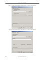
< Structured Assembler Options > Dialog Box (When << Others >> Tab Is Selected) ... 89
< Edit Option > Dialog Box ... 92
< Add Option > Dialog Box ... 92
I/O Files of Assembler ... 94
< Assembler Options > Dialog Box (When << Output1 >> Tab Is Selected) ... 140
< Assembler Options > Dialog Box (When << Output2 >> Tab Is Selected) ... 141
< Assembler Options > Dialog Box (When << Others >> Tab Is Selected) ... 141
< Edit Option > Dialog Box ... 145
< Add Option > Dialog Box ... 145
Memory Area Names ... 151
Specific Examples of Segment Allocation ... 155
< Linker Options > Dialog Box (When << Output1 >> Tab Is Selected) ... 194
< Linker Options > Dialog Box (When << Output2 >> Tab Is Selected) ... 195
< Linker Options > Dialog Box (When << Library >> Tab Is Selected) ... 195
< Linker Options > Dialog Box (When << Others >> Tab Is Selected) ... 196
< Edit Option > Dialog Box ... 200
< Add Option > Dialog Box ... 200
I/O Files of Object Converter ... 202
Intel Standard Format ... 205
Intel Extended Format ... 206
Motorola S-Type Format ... 212
Symbol Value Formats ... 217
< Object Converter Options > Dialog Box (When << Output1 >> Tab Is Selected) ... 237
< Object Converter Options > Dialog Box (When << Output2 >> Tab Is Selected) ... 238
< Object Converter Options > Dialog Box (When << Others >> Tab Is Selected) ... 238
I/O Files of Librarian ... 242
Procedure for Creating Library File ... 244
< Librarian Options > Dialog Box (When << Output >> Tab Is Selected) ... 268
User’s Manual U17199EJ1V0UM
13
8-4
8-5
8-6
9-1
9-2
9-3
B-1
14
< Librarian Options > Dialog Box (When << Others >> Tab Is Selected) ... 269
< Library File Name > Dialog Box ... 272
< Subcommand > Dialog Box ... 273
I/O Files of List Converter ... 276
< List Converter Options > Dialog Box (When << Output >> Tab Is Selected) ... 291
< List Converter Options > Dialog Box (When << Others >> Tab Is Selected) ... 292
Address View ... 382
User’s Manual U17199EJ1V0UM
LIST OF TABLES
Table No. Title , Page
1-1
1-2
1-3
2-1
4-1
4-2
5-1
5-2
5-3
5-4
6-1
6-2
6-3
6-4
6-5
6-6
7-1
7-2
7-3
7-4
7-5
7-6
7-7
7-8
7-9
7-10
7-11
7-12
7-13
7-14
7-15
7-16
7-17
7-18
8-1
8-2
8-3
9-1
9-2
9-3
10-1
10-2
10-3
10-4
10-5
10-6
10-7
10-8
10-9
10-10
10-11
10-12
10-13
Maximum Performance of Structured Assembler ... 33
Maximum Performance of Assembler ... 34
Maximum Performance of Linker ... 35
Supply Medium of Assembler Package ... 37
I/O Files of Structured Assembler Preprocessor ... 67
Structured Assembler Options ... 73
I/O Files of Assembler ... 93
Assembler Options ... 100
Order of Precedence of Assembler Options ... 102
Characters That Can Be Written as Titles ... 122
I/O Files of Linker ... 146
Segment Allocation Groups (External ROM, etc.) ... 148
Types of Directives ... 149
Segment Location According to Combination of Memory Area Name Specification and Memory Space
Name ... 154
Linker Options ... 159
Order of Precedence of Linker Options ... 161
I/O Files of Object Converter ... 201
Output File Types for Extended Space ... 203
File Type When -ZF Option Is Specified ... 203
Extended Tech Header Field ... 208
Character Values for Check Sum Evaluation ... 208
Data Block Format for Extended Tech ... 208
Termination Block Format for Extended Tech ... 209
Symbol Block Format for Extended Tech ... 210
Symbol Block Section Definition Fields for Extended ... 211
Symbol Block Symbol Definition Fields for Extended Tech ... 211
Motorola HEX File Record Types ... 212
General Format for Each Record ... 212
Meanings of Fields ... 213
Values of Symbol Attributes ... 217
Object Converter Options ... 221
File Type When -ZF Option Is Specified ... 223
Type of HEX Format Object Module File for Extended Space ... 224
Type of Symbol Table File for Extended Space ... 225
I/O Files of Librarian ... 241
Librarian Options ... 249
Subcommands ... 257
I/O Files of List Converter ... 275
Type of Specification File When List Converter Is Started ... 280
List Converter Options ... 283
Lists Output by Structured Assembler Preprocessor ... 294
Explanation of Error List Output Items (when the structured assembler preprocessor is started up) ... 295
Lists Output by Assembler ... 296
Explanation of Assemble List File Headers Output Items ... 297
Explanation of Assemble list Output Items ... 298
Explanation of Symbol list Output Items ... 300
Explanation of Cross-reference Output Items ... 301
Explanation of Error List Output Items (when the assembler is started up) ... 303
Lists Output by Linker ... 304
Explanation of Link List File Header Output Items ... 304
Explanation of Map List Output Items ... 306
Explanation of Public Symbol List Output Items ... 308
Explanation of Local Symbol List Output Items ... 309
User’s Manual U17199EJ1V0UM
15
10-14
10-15
10-16
10-17
10-18
12-1
12-2
12-3
12-4
12-5
12-6
12-7
12-8
12-9
12-10
12-11
12-12
B-1
B-2
C-1
C-2
C-3
C-4
C-5
C-6
D-1
16
Explanation of Error List Output Items(when the linker is started up) ... 310
Explanation of Object Converter Output Items ... 311
List Output by Librarian ... 312
Explanation of Library Data Output List Output Items ... 312
Lists Output by List Converter ... 313
Structured Assembler Preprocessor Error Messages ... 323
Assembler Error Messages ... 329
Linker Error Messages ... 340
Object Converter Error Messages ... 349
Librarian Error Messages ... 353
List Converter Error Messages ... 357
Error Messages Displayed by the Structured Assembler Preprocessor (ST78K0) DLL ... 361
Error Messages Displayed by the Assembler (RA78K0) DLL ... 364
Error Messages Displayed by the Linker (LK78K0) DLL ... 367
Error Messages Displayed by the Object Converter (OC78K0) DLL ... 370
Error Messages Displayed by the Librarian (LB78K0) DLL ... 371
Error Messages Displayed by the List Converter (LCNV78K0) DLL ... 372
Example of output in Intel extended HEX format (flash memory real address) ... 383
Example of output in Intel extended HEX format (bank number + CPU address) ... 384
Structured Assembler Options ... 385
Assembler Options ... 387
List of Linker Options ... 390
List of Object Converter Options ... 393
List of Librarian Options ... 395
List of List Converter Options ... 396
List of Subcommands ... 397
User’s Manual U17199EJ1V0UM
CHAPTER 1 GENERAL
CHAPTER 1
GENERAL
This chapter describes the role of the RA78K0 in microcontroller software development and the features of the
RA78K0.
1.1
Assembler Overview
The RA78K0 Assembler Package (hereafter referred to as "the RA78K0") is a generic term for a series of
programs designed to translate source programs coded in the assembly language for 78K0 Series microcontrollers
into machine language coding.
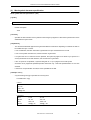
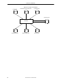
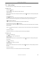
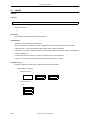
The RA78K0 contains six programs : Structured Assembler Preprocessor, Assembler, Linker, Object Converter,
Librarian, and List Converter.
In addition, a PM plus that helps you perform a series of operations including editing, compiling/assembling,
linking, and debugging your program on Windows is also supplied with the RA78K0.
Figure 1-1 RA78K0 Assembler Package
STRUCTURED ASSEMBLER PREPROCESSOR
ASSEMBLER
LINKER
RA78K0 Assembler Package
OBJECT CONVERTER
LIBRARIAN
LIST CONVERTER
PM plus
User’s Manual U17199EJ1V0UM
17
CHAPTER 1 GENERAL
1.1.1
What is an assembler?
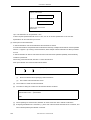
(1) Assembly language and machine language
An assembly language is the most fundamental programming language for a microcontroller.
Programs and data are required for the microprocessor in a microcontroller to do its job. These programs and
data must be written by users to the memory of the microcontroller. The programs and data handled by the
microcontroller are collections of binary numbers called machine language. For users, however, machine
language code is difficult to remember, causing errors to occur frequently. Fortunately, methods exist whereby
English abbreviations or mnemonics are used to represent the meanings of the original machine language
codes in a way that is easy for users to comprehend. The basic programming language system that uses this
symbolic coding is called an assembly language.
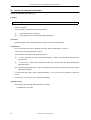
Since machine language is the only programming language in which a microcontroller can handle programs,
however, another program is required that translates programs created in assembly language into machine
language. This program is called an assembler.
Figure 1-2 Flow of Assembler
Program written in
Program coded in
assembly language
sets of binary
(Source module file)
18
(Assembler)
User’s Manual U17199EJ1V0UM
(Object module file)
CHAPTER 1 GENERAL
1.1.2
Development process and RA78K0
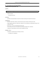
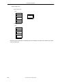
(1) Development of microcontroller-related products and the role of RA78K0
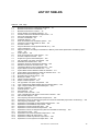
Figure 1-3 illustrates the position of "assembly-language programming in the product development process".
Figure 1-3 Development Process of Microcontroller-Applied Products
Product planning
System design
Hardware development
Software development
Logic design
Software design
Manufacturing
Program coding in
assembly language
Position of
RA78K0
Assembly
Inspection
NO
NO
OK
OK
YES
YES
Debugging
NO
OK
YES
System evaluation
Product marketing
User’s Manual U17199EJ1V0UM
19
CHAPTER 1 GENERAL
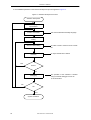
A more detailed explanation of the software development process appears in Figure 1-4.
Figure 1-4 Software Development Process
Software development
Creation of program
specifications
Creation of flowchart
This uses the RA78K0 assembly language.
Coding
Source module editing
An editor is used to create a source module
file.
An object module file is created.
Assembly
YES
Errors?
NO
The operation of the software is checked
Debugging
using a hardware debugger such as an
in-circuit emulator.
NO
OK
YES
System evaluation
20
User’s Manual U17199EJ1V0UM
CHAPTER 1 GENERAL
The RA78K0 is then applied to the assembly process.
Figure 1-5 RA78K0 Assembly Process
Assembly process
From editing of the source
module…
Output from the object module file
Assembly
YES
Assembly errors?
NO
Output from the load module file
Linking
Conversion of object
Output of HEX-format object module file
…to debugging
User’s Manual U17199EJ1V0UM
21
CHAPTER 1 GENERAL
1.1.3
What is a relocatable assembler?
The machine language translated from a source language by the assembler is stored in the memory of the
microcontroller before use. To do this, the location in memory where each machine language instruction is to be
stored must already be determined.
Therefore, information is added to the machine language assembled by the assembler, stating where in memory
each machine language instruction is to be located.
Depending on the method of locating addresses to machine language instructions, assemblers can be broadly
divided into "absolute assemblers" and "relocatable assemblers".
-
Absolute assembler
An absolute assembler locates machine language instructions assembled from the assembly language to
absolute addresses.
-
Relocatable assembler
In a relocatable assembler, the addresses determined for the machine language instructions assembled
from the assembly language are tentative. Absolute addresses are determined subsequently by the linker.
In the past, when a program was created with an absolute assembler, programmers had to, as a rule, complete
programming at the same time. However, if all the components of a large program are created as a single entity,
the program becomes complicated, making analysis and maintenance of the program difficult. To avoid this, such
large programs are developed by dividing them into several subprograms, called modules, for each functional unit.
This programming technique is called modular programming.
1.1.4
Advantages of a relocatable assembler
A relocatable assembler is an assembler suitable for modular programming, which has the following advantages:
(1) Increase in development efficiency
It is difficult to write a large program all at the same time. In such cases, dividing the program into modules for
each function enables two or more programmers to develop subprograms in parallel to increase development
efficiency.
Furthermore, if any bugs are found in the program, it is not necessary to assemble the entire program just to
correct one part of the program, and only a module which must be corrected can be reassembled. This
shortens debugging time.
22
User’s Manual U17199EJ1V0UM
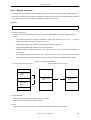
CHAPTER 1 GENERAL
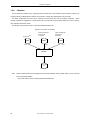
Figure 1-6 Reassembly for Debugging
Program consisting of a
Program consisting of two or
single modules
more modules
Module
Bugs are
found!
Module
Bugs are
found!
Module
Entire program
XXX
must be
Only this module
XXX
assembled
must be
Module
assembled
again.
again.
Module
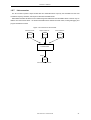
(2) Utilization of resources
Highly reliable, highly versatile modules which have been previously created can be utilized for creation of
another program. If you accumulate such high-versatility modules as software resources, you can save time
and labor in developing a new program.
Figure 1-7 Program Development Using Existing Module
Module A
Module B
Module C
Module D
New module
Module A
New module
Module D
New program
User’s Manual U17199EJ1V0UM
23
CHAPTER 1 GENERAL
1.2
Overview of Features of RA78K0
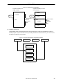
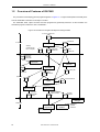
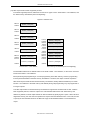
The procedure for developing general programs appears in Figure 1-8. Program development essentially flows
from the assembler to the linker to the object converter.
The assembler, linker, object converter and other programs are generically referred to as the "RA78K0." the
assembler program is referred to as the "assembler."
Figure 1-8 Procedure for Program Development Using RA78K0
C source module file
Include file
C compiler
C compiler
Startup
module file for
the C compiler
Assembler
module file
Object
module file
Structured
assembler
module file
Structured
assembler
Librarian
Assembler
Library file
Assembler
module file
Object
module file
RA78K0
Load module file
Linker
List converter
Object converter
HEX-format
object module
file
Absolute
assemble
list file
Symbol
table file
Integrated
debugger
Debugger
PROM
programmer
Flash programmer
24
User’s Manual U17199EJ1V0UM
In-circuit
emulator
Dedicated
parallel
interface
CHAPTER 1 GENERAL
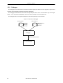
1.2.1
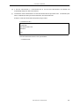
Creating a source module file using an editor
A single program can be divided into two or more modules according to function. A single module can be used
as a coding unit or an assembler input unit.
A module which is used as an input unit for the assembler is called a source module. After the coding of each
source module is finished, the source module is written to a file using an editor. The file created in this way is
called a source module file.
A source module file is used as an assembler input file.
Figure 1-9 Creating Source Module File
Program
Source module
Source module
END
Source module
END
END
Source module
Writing to file (editor)
END
Source module file
User’s Manual U17199EJ1V0UM
25
CHAPTER 1 GENERAL
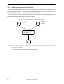
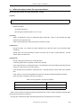
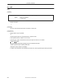
1.2.2
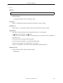
Structured assembler preprocessor
The structured assembler preprocessor is a program whose purpose is to create structured programming using
assembly language instructions.
The structured assembler preprocessor inputs source programs written in
structured assembly language to input the source program for the assembler.
For more information on the structured assembler preprocessor and structured assembly language, refer to the
separate RA78K0 Structured Assembly Language User’s Manual.
Figure 1-10 Function of Structured Assembler Preprocessor
Structured
assembler
source file
Device fileNote
Input
Input
Structured assembler
preprocessor
Output
Note
Obtain the device file by downloading it from the Online Delivery Service (ODS), which can be accessed
from the following Website.
http://www.necel.com/micro/ods/eng/tool/DeviceFile/list.html
26
User’s Manual U17199EJ1V0UM
CHAPTER 1 GENERAL
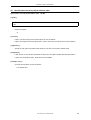
1.2.3
Assembler
The assembler is a program which inputs the source module file and converts the assembly language into a
collection of binary instructions (machine language). If the assembler discovers errors in the descriptions in the
source module, it outputs an assembly error. If no assembly errors are found, the assembler outputs an object
module file which specifies location data such as where in memory the machine language data and each machine
language should be stored. The assembly data is output as an assemble list file.
Figure 1-11 Function of Assembler
Source module file
Device fileNote
Input
Input
Assembly language
is converted into
machine language
Assembly
errors?
YES
NO
Assembler
Object module file
Output
Object module file
is created
List file is created
Output
Assemble list file
Note
Obtain the device file by downloading it from the Online Delivery Service (ODS), which can be accessed
from the following Website.
http://www.necel.com/micro/ods/eng/tool/DeviceFile/list.html
User’s Manual U17199EJ1V0UM
27
CHAPTER 1 GENERAL
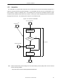
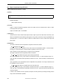
1.2.4
Linker
The linker inputs the multiple object module files output by the compiler and the assembler and links them to
output a single load module file (linking must be performed even if only one object module file is input).
The linker determines the location addresses for the relocatable segments in the input modules.
This
determines the values for the relocatable symbols and external-reference symbols so that the correct values can
be embedded in the load module file.
Figure 1-12 Function of Linker
Device fileNote
Object module file
Input
Input
Library file
Directive file
Input
Input
Linker
Output
Output
Load module file
Note
Link map file
Obtain the device file by downloading it from the Online Delivery Service (ODS), which can be accessed
from the following Website.
http://www.necel.com/micro/ods/eng/tool/DeviceFile/list.html
28
User’s Manual U17199EJ1V0UM
CHAPTER 1 GENERAL
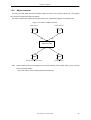
1.2.5
Object converter
The object converter inputs the load module file output by the linker and converts the file format. The resulting
file is output as a HEX-format object module file.
The object converter also outputs symbol data necessary for symbolic debugging as a symbol table file.
Figure 1-13 Function of Object Converter
Device fileNote
Load module file
Input
Input
Object Converter
Output
Output
HEX-format object module file
Note
Symbol table file
Obtain the device file by downloading it from the Online Delivery Service (ODS), which can be accessed
from the following Website.
http://www.necel.com/micro/ods/eng/tool/DeviceFile/list.html
User’s Manual U17199EJ1V0UM
29
CHAPTER 1 GENERAL
1.2.6
Librarian
For convenience and ease of use, a general-purpose module with a clear interface may be stored in a library. By
creating a library, multiple object modules can be stored in a single file, making them easy to handle.
The linker incorporates a function which retrieves from the library file only the modules necessary. When
multiple modules are registered in a single library file, the module files can be linked without the need to specify
each individual module file name.
The librarian is the program used to create and update the library file.
Figure 1-14 Function of Librarian
Device fileNote
Input
Object module files
output by the
C compiler
Input
Object module files
output by the
assembler
Input
Librarian
Output
Library file
Note
Obtain the device file by downloading it from the Online Delivery Service (ODS), which can be accessed
from the following Website.
http://www.necel.com/micro/ods/eng/tool/DeviceFile/list.html
30
User’s Manual U17199EJ1V0UM
CHAPTER 1 GENERAL
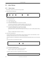
1.2.7
List converter
The list converter inputs the object module files and assemble list file output by the assembler and the load
module file output by the linker, and outputs an absolute assemble list file.
Relocatable assemble list files have the disadvantage that addresses and relocatable values in the list may be
different from their actual values. An absolute assemble list file determines these values, making debugging and
program maintenance easier.
Figure 1-15 Function of List Converter
Assemble list file
Input
Object module file
Input
Load module file
Input
List Converter
Output
Absolute assemble list file
User’s Manual U17199EJ1V0UM
31
CHAPTER 1 GENERAL
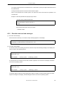
1.2.8
Debugger
The debugger for the 78K0 Series is a software tool which displays the data from source programs, registers and
memories in their respective windows and performs debugging.
The debugger downloads the load module file output by the linker to the in-circuit emulator (IE) of the target
system. It can also perform debugging at the source level by reading the source program file.
The debugger and IE are separate packages and are sold separately from the RA78K0.
Figure 1-16 Function of Debugger
Source program
Load module file
- Assembler
- Structured
assembler
- C compiler
- Object module file
- Debugging
information
Debugger
Dedicated parallel interface
In-circuit emulator
32
User’s Manual U17199EJ1V0UM
CHAPTER 1 GENERAL
1.3
Reminders Before Program Development
Refer to the following before beginning program development.
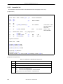
1.3.1
Maximum performance of RA78K0
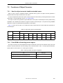
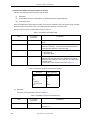
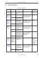
(1) Maximum performance of structured assembler
Table 1-1 Maximum Performance of Structured Assembler
Item
Line length (not including LF or CR)
Maximum Value
2048 characters
Number of symbols registered in #define directive (excluding reserved words)
512 symbols
Character length of symbol registered in #define directive
31 characters
Nesting levels in control statement
31 levels
Nesting levels in #ifdef directive
8 levels
#defcallt directives
32
Nesting of #include directives
Not supported
Number of redefinitions by #define directive
31 times
Number of operands assigned in a series
33Note1
Logical operator operands
17Note2
Number of symbols defined by -D option
30
Number of library file paths specifiable by -I option
64
Notes 1 The maximum value is expressed as follows.
S1=S2= ... S32=S33
Up to 33 symbols and 32 equal (=) signs can be inserted.
Notes 2 The maximum value is expressed as follows.
expression 1&&expression 2&& ... &&expression 16&&expression 17
Up to 17 expression s and 16 "&&" (or "||") signs can be inserted.
User’s Manual U17199EJ1V0UM
33
CHAPTER 1 GENERAL
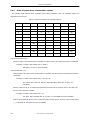
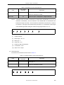
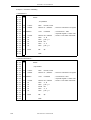
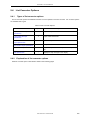
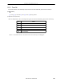
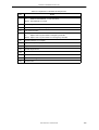
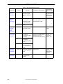
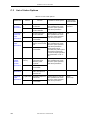
(2) Maximum performance of assembler
Table 1-2 Maximum Performance of Assembler
Item
Number of symbols (local + public)
Number of symbols that can be output to cross
reference list
65535
65534Note1
Maximum marco body size referenced by one marco
1 MB
Total size of all macro bodies
10 MB
Number of segments in 1 file
256
Macros and include specifications in 1 file
10000
Macros and include specifications in 1 include file
10000
Relocation informationNote2
65535
Line number information
65535
BR quasi directives in 1 file
32767
Numbers of characters on 1 line of source code
Symbol length
2048Note3
256 characters
Number of switch name definitionsNote4
1000
Character length of switch nameNote4
31 characters
Character length of segment name
8 characters
Character length of module name (NAME quasi
directive)
8 characters
Number of virtual parameters in MACRO quasi directive
16
Number of actual parameters in macro reference
16
Number of actual parameters in IRP quasi directive
16
Number of local symbols in macro body
64
Total number of local symbols in expanded macro
65535
Nesting levels in macro (macro reference, REPT quasi
directive, IRP quasi directive)
8 levels
Number of characters specifiable by TITLE control
instruction, -LH option
60Note5
Number of characters specifiable by SUBTITLE control
instruction
34
Maximum Performance
72
Include file nesting levels in 1 file
8 levels
Conditional assembly nesting levels
8 levels
Number of include file paths specifiable by -I option
64
Number of symbols definable by -D option
30
User’s Manual U17199EJ1V0UM
CHAPTER 1 GENERAL
Notes 1 Excluding the number of module names and section names.
Memory is used. If there is no memory, a file is used.
Notes 2
Information to be passed to the linker if the symbol value cannot be resolved by the assembler.
For example, if an externally referenced symbol is to be referenced by the MOV instruction, two
pieces of relocation information are generated in a .rel file.
Notes 3 Including CR and LF codes. If more than 2048 characters are written on one line, a warning
message is output and the 2049th character and those that follow are ignored.
Notes 4 The switch name is set as true/false by the SET/RESET quasi directive and is used by $IF, etc.
Notes 5 If the maximum number of characters that can be specified in one line of the assemble list file ("X") is
119, this figure will be "X - 60" or less.
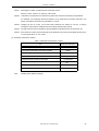
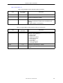
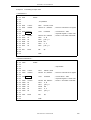
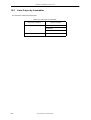
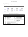
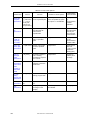
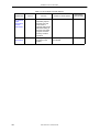
(3) Maximum performance of linker
Table 1-3 Maximum Performance of Linker
Item
Number of symbols (local + public)
65535
Line number information of the same segment
65535
Number of segments
65535
Input modules
1024
Character length of memory area name
Number of memory areas
Note
Maximum Performance
31 characters
100Note
Number of library files specifiable by -B option
10
Number of include file paths specifiable by -I option
64
Including those defined by default.
User’s Manual U17199EJ1V0UM
35
CHAPTER 1 GENERAL
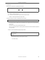
1.4
Features of RA78K0
The RA78K0 has the following features :
(1) Macro function
When the same group of instructions must be described in a source program over and over again, a macro
can be defined by giving a single macro name to the group of instructions. By using this macro function,
coding efficiency and readability of the program can be increased.
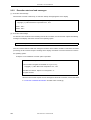
(2) Optimize function of branch instructions
The RA78K0 has a directive to automatically select a branch instruction (BR directive).
To create a program with high memory efficiency, a byte branch instruction must be described according to
the branch destination range of the branch instruction. However, it is troublesome for the programmer to
describe a branch instruction by paying attention to the branch destination range for each branching. By
describing the BR directive, the assembler generates the appropriate branch instruction according to the
branch destination range. This is called the optimization function of branch instructions.
(3) Conditional assembly function
With this function, a part of a source program can be specified for assembly or non-assembly according to a
predetermined condition. If a debug statement is described in a source program, whether or not the debug
statement should be translated into machine language can be selected by setting a switch for conditional
assembly. When the debug statement is no longer required, the source program can be assembled without
major modifications to the program.
36
User’s Manual U17199EJ1V0UM
CHAPTER 2 PRODUCT OUTLINE AND INSTALLATION
CHAPTER 2
PRODUCT OUTLINE AND
INSTALLATION
This chapter explains the procedure used to install the files stored in the supply media of the RA78K0 in the user
development environment (host machine) and the procedure to uninstall these files from the user development
environment.
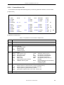
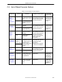
2.1
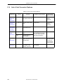
Host Machine and Supply Medium
The assembler package supports the development environments shown in Table 2-1. The supply medium
differs depending on the host machine.
Table 2-1 Supply Medium of Assembler Package
Host Machine
OS
Supply Medium
IBM PC/AT compatible
Japanese Windows (98/Me/2000/XP/NT 4.0)Note
English Windows (98/Me/2000/XP/NT 4.0)Note
CD-ROM
HP9000 Series 700TM
HP-UXTM (Rel. 10.10 or later)
CD-ROM
SPARCstation Series
SunOSTM (Rel. 4.1.4 or later)
SolarisTM (Rel. 2.5.1 or later)
Note To use the assembler in Windows, PM plus is necessary.
If PM plus is not used, each tool included in the RA78K0 assembler package can be used from the DOS
prompt (Windows 98/Me) or command prompt (Windows 2000/XP/NT 4.0)
User’s Manual U17199EJ1V0UM
37
CHAPTER 2 PRODUCT OUTLINE AND INSTALLATION
2.2
Installation
The procedure for installing to the host machine the files provided in the RA78K0’s supply media is described
below.
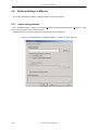
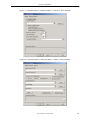
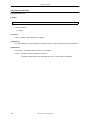
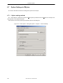
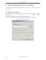
2.2.1
Installation of Windows version
(1) Starting up Windows
Power on the host machine and peripherals and start Windows.
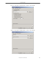
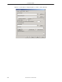
(2) Set supply media
Set the RA78K0’s supply media in the appropriate drive (CD-ROM drive) of the host machine. The setup
programs will start automatically. Perform the installation by following the messages displayed in the monitor
screen.
Caution
If the setup program does not start automatically, execute SETUP.EXE in the RA78K0\DISK1 folder.
(3) Confirmation of files
Using Windows Explorer, etc., check that the files contained in the RA78K0’s supply media have been
installed to the host machine.
For the details of each folder, refer to "2.4 Directory Configuration".
38
User’s Manual U17199EJ1V0UM
CHAPTER 2 PRODUCT OUTLINE AND INSTALLATION
2.2.2
Installation of UNIX version
Install the UNIX version with the following procedure. Installation to /nectools/bin is assumed here.
(1) Login
Log in to the host machine.
(2) Directory selection
Go to the install directory.
%cd /nectools/bin
(3) Setting of supply media
Set the CD-ROM in the CD-ROM drive.
(4) Copying of files
Execute the cp command to copy the files from the CD-ROM (copy the files after checking that the CD-ROM
has been set in the CD-ROM drive).
(5) Setting of environmental variable PATH
Add /nectools/bin to the environmental variable PATH.
User’s Manual U17199EJ1V0UM
39
CHAPTER 2 PRODUCT OUTLINE AND INSTALLATION
2.3
Installation of Device Files
Obtain the device file by downloading it from the Online Delivery Service (ODS), which can be accessed from the
following Website.
http://www.necel.com/micro/ods/eng/tool/DeviceFile/list.html
2.3.1
Installation of Windows version
Use the "device file installer" to install the device files. The "device file installer" is installed at the same time as
the RA78K0.
2.3.2
Installation of UNIX version
Either specify the directory for device files with the -y option, or specify the directory (example : -y/nectools/dev),
and copy the device files to a directory with the assembler execution format (example : /nectools/bin).
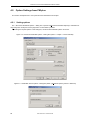
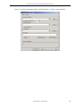
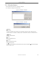
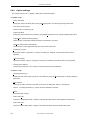
2.3.3
Registry registration of device files
If the device files are already installed, a message prompting you to perform registry registration of the device
files may be displayed during RA78K0 installation.
If currently using a 32-bit environment, register the device file used for the RA78K0 (Ver. 3.30 or earlier, 16-bit
environment) to a registry (32-bit environment).
Registry registration can also be done using the device file installer after RA78K0 installation has been
completed.
The registry registration procedure is as follows.
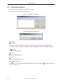
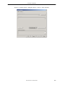
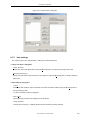
(1) Startup of "device file installer"
(2) Source selection
Click the [Browse] button and select "NECDEV.INI" used in the 16-bit environment.
Select a file registered to a registry from the device file displayed in the source list box.
(3) Move
Register the file to the registry (32-bit environment) by clicking the [Move] button.
40
User’s Manual U17199EJ1V0UM
CHAPTER 2 PRODUCT OUTLINE AND INSTALLATION
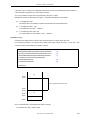
2.4
2.4.1
Directory Configuration
Windows version directory configuration
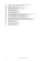
The standard directory displayed during installation is "NECTools32\" on the drive where Windows is installed.
The configuration of the install directory is as shown below. The drive and install directory may be changed during
installation. Install PM plus and the RA78K0 in the same directory.
Figure 2-1 Directory Configuration
\NECTools32\
bin\
st78k0.exe
Execution format of structured assembler preprocessor
ra78k0.exe
Execution format of assembler
lk78k0.exe
Execution format of linker
oc78k0.exe
Execution format of object converter
lb78k0.exe
Execution format of librarian
lcnv78k0.exe
lb78k0e.exe
lb78k0p.exe
Execution format of list converter
Interface tool between library and DLL of PM plus environment
Standalone start up library
ra78k0.is*
*78k0p.dll
File used by assembler
DLL tool for PM plus
*78k0.hlp
Help file for starting command line (text file)
doc\
User’s manual and supplementary explanations
hlp\
Online manual
setup\
Data files for installation and uninstallation
smp78k0\ra78k0\
k0main.asm
Assembler sample program
k0sub.asm
Assembler sample program
ra.bat
Batch file for assembler sample program
readme.doc
Explanation of sample program and batch file (text file)
test1.s
test2.s
testinc.s
Structured assembler sample program
Structured assembler sample program
Structured assembler sample program
st.bat
Batch file for structured assembler sample program
Remark The explanations in this manual assume installation to the standard directory with the default program
folder name "NECTools32" according to the default directions of the setup program.
User’s Manual U17199EJ1V0UM
41
CHAPTER 2 PRODUCT OUTLINE AND INSTALLATION
2.4.2
UNIX version directory configuration
The file configuration after installation is as follows. The following assumes installation in /nectools/bin.
Figure 2-2 Directory Configuration
/nectools/
bin/
st78k0
Executable format of structured assembler preprocessor
ra78k0
Executable format of assembler
lk78k0
Executable format of linker
oc78k0
Executable format of object converter
lb78k0
Executable format of librarian
lcnv78k0
*.hlp
ra78k0.is*
Executable format of list converter
Help file corresponding to each program (text file)
Table file defining instruction set used by assembler
*.asm , *.s
*.sh
Sample program for installation confirmation
Batch file for installation confirmation
*.sh
Batch file for installation confirmation
readme.doc
Explanation of use of install confirmation shell file (text file)
It is recommended to install the C compiler integrated debugger, system simulator, and device file to the
directory to which the assembler package has been installed.
42
User’s Manual U17199EJ1V0UM
CHAPTER 2 PRODUCT OUTLINE AND INSTALLATION
2.5
2.5.1
Uninstallation Procedure
Uninstallation of Windows version
The procedure for uninstalling the files installed to the host machine is described below.
(1) Windows startup
Power on the host machine and peripherals and start Windows.
(2) Opening [Control Panel] window
Press the [Start] button and select [Settings]-[Control Panel] to open the [Control Panel] window.
(3) Opening of [Add/Remove Programs] window
Double-click the [Add/Remove Programs] icon in the [Control Panel] window to open the [Add/Remove
Programs] window.
Caution
On Windows XP, [Add or Remove Programs] is displayed instead of [Add/Remove Programs]
(4) Removing RA78K0
After selecting "NEC RA78K0 78K/0 Assembler Vx.xx" from the list of installed software displayed in the
[Install/Uninstall] tab in the [Add/Remove Programs] window, click the [Add/Remove] button.
When the [System Settings Change] window is opened, click the [Yes ] button.
(5) Confirmation of files
Using Windows Explorer, etc., check that the files installed to the host machine have been uninstalled. For the
details of each folder, refer to "2.4 Directory Configuration".
2.5.2
Uninstallation of UNIX version
The files copied in "2.2.2 Installation of UNIX version" with the rm command.
User’s Manual U17199EJ1V0UM
43
CHAPTER 2 PRODUCT OUTLINE AND INSTALLATION
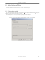
2.6
2.6.1
Environment Settings
Host machine (IBM PC/AT compatibles)
The RA78K0 runs on a machine with a 32-bit CPU such as i386TM or above.
Because the assembler package runs with a 32-bit CPU by using DOS Extender, it is designed to run on the
following OSs :
-
DOS prompt of Windows 98/Me
-
Command prompt of Windows 2000/XP/NT 4.0
A protect memory of 7M bytes or more is necessary for operation.
The restrictions on the environmental variables of each OS are as follows :
2.6.2
Environmental variables
Set the following environmental variables. If the assembler package has been installed using the Windows
installer, the necessary environmental variables are automatically set.
PATH :
Specifies the directory to which the executable format of the assembler is stored.
TMP :
Specifies a directory where a temporary file is to be created
(valid only with the IBM PC/AT compatibles)
INC78K0 :
Specifies a directory where the include file is searched.
LIB78K0 :
Specifies the directory where a library is searched, if the library is used.
LANG78K : Specifies the kanji code (2-byte code) described in the comment.
[Example]
-
With IBM PC/AT compatibles
PATH = %PATH% ; c:\NECTools32\bin
-
set
TMP = c:\tmp
set
INC78K0 = c:\NECTools32\inc78k0
set
LIB78K0 = c:\NECTools32\lib78k0
set
LANG78K = SJIS
With HP9000 Series 700 or SPARCstation Series
< Example when csh is used >
44
set
path = ( $path /ra78k0 )
setenv
INC78K0 /ra78k0
setenv
LIB78K0 /ra78k0
setenv
LANG78K EUC
User’s Manual U17199EJ1V0UM
CHAPTER 2 PRODUCT OUTLINE AND INSTALLATION
< Example when sh is used >
PATH = $PATH:/ra78k0
INC78K0 = /ra78k0
LIB78K0 = /ra78k0
LANG78K = EUC
export
2.6.3
PATH INC78K0 LIB78K0 LANG78K
Kanji code in source file
-
Kanji (2-byte characters) can be used in specific places (comments, etc.) in the source file.
-
Specify the kanji code type using an environmental variable (LANG78K), kanji code control instruction
(KANJICODE), or kanji code specification option (-ZE/-ZS/-ZN).
User’s Manual U17199EJ1V0UM
45
CHAPTER 3 EXECUTION PROCEDURE OF RA78K0
CHAPTER 3
EXECUTION PROCEDURE OF
RA78K0
This chapter explains the procedures for using the assembler package RA78K0, from assembling to object
conversion.
Sample programs "k0main.asm" and "k0sub.asm" are assembled, linked, and converted into objects in
accordance with the execution procedures explained.
In this section, how to run the assembler package on command line is explained.
3.1
3.1.1
Before Executing RA78K0
Sample programs
Among the files stored on the system disk are "k0main.asm" and "k0sub.asm". These files are a sample
program for use in verifying the operation of the assembler package.
In later assembler operation, these files will be input to the assembler as source program files.
k0main.asm :
Main module
k0sub.asm :
Sub module
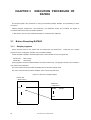
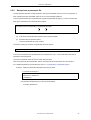
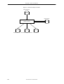
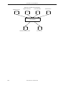
These programs consist of hexadecimal data converted to ASCII code. The program consists of two modules, a
main routine and a subroutine.
The name of the main routine module is SAMPM, and it is stored in (k0main.asm).
The name of the subroutine module is SAMPS, and it is stored in (k0sub.asm).
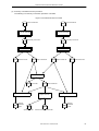
Figure 3-1 Structure of Sample Program
k0main.asm
< Main routine >
NAME
SAMPM
k0sub.asm
< Subroutine >
CALL ...
NAME
END
END
46
User’s Manual U17199EJ1V0UM
SAMPS
CHAPTER 3 EXECUTION PROCEDURE OF RA78K0
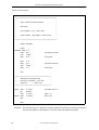
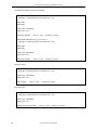
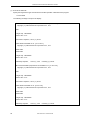
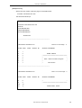
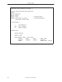
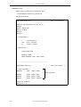
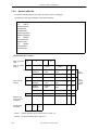
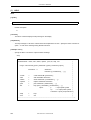
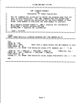
- k0main.asm (Main routine)
NAME
SAMPM
; ***************************************************
;*
*
;*
HEX -> ASCII Conversion Program *
;*
;*
*
main-routine
;*
*
*
; ****************************************************
PUBLIC MAIN , START
EXTRN CONVAH
EXTRN _@STBEG
DATA
DSEG
saddr
HDTSA : DS
1
STASC : DS
2
CODE
AT 0H
CSEG
MAIN : DW
START
CSEG
START :
; chip initialize
MOVW SP , #_STBEG
MOV
HDTSA , #1AH
MOVW HL , #HDTSA
CALL
!CONVAH
; set hex 2-code data in HL register
; convert ASCII <- HEX
; output BC-register <- ASCII code
MOVW DE , #STASC
MOV
; set DE <- store ASCII code table
A,B
MOV
[ DE ] , A
INCW
DE
MOV
A,C
MOV
[ DE ] , A
BR
$$
END
User’s Manual U17199EJ1V0UM
47
CHAPTER 3 EXECUTION PROCEDURE OF RA78K0
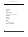
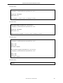
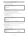
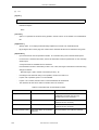
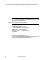
- k0sub.asm (Subroutine)
NAME
SAMPS
; ************************************************************************
;*
;*
*
HEX -> ASCII Conversion Program
*
sub-routine
*
input condition : ( HL ) <- hex 2 code
*
output condition :BC-register <- ASCII 2 code
*
;*
;*
*
;*
;*
*
;*
;*
*
;*
*
;*************************************************************************
PUBLIC CONVAH
CSEG
CONVAH : XOR A , A
ROL4
[ HL ]
CALL
!SASC
MOV
B,A
MOV
A,A
ROL4
[ HL ]
CALL
!SASC
MOV
C,A
; hex upper code load
; store result
; hex lower code load
; store result
RET
; **************************************************************
;*
subroutine convert ASCII code
*
;*
input Acc ( lower 4bits ) <- hex code
*
;*
output Acc
*
<- ASCII code
; **************************************************************
SASC : CMP
A , #0AH
; check hex code > 9
BC
$SASC1
ADD
A , #07H
; bias ( +7 )
SASC1 : ADD
A , #30H
; bias ( +30 )
RET
END
Remarks 1 This sample program is a reference program, prepared for the purpose of teaching you about the
functions and operation of the RA78K0. It cannot be used as an application program.
48
User’s Manual U17199EJ1V0UM
CHAPTER 3 EXECUTION PROCEDURE OF RA78K0
Remarks 2 This sample program does not operate the default settings of the register bank selection flags
(RBS0, RBS1). The settings for these items are therefore as follows.
Register bank
3.1.2
0 (FEF8H to FEFFH)
Configuration of sample program
The following describes the sample program that is used as an example for the operations described below.
k0main.asm :
Main module
k0sub.asm :
Sub module
mylib.lib :
Library file (this is not used here.)
sample.dr :
Directive file
User’s Manual U17199EJ1V0UM
49
CHAPTER 3 EXECUTION PROCEDURE OF RA78K0
3.2
Execution Procedure of RA78K0
The batch files (ra.bat) in the system disk are used for the RA78K0 operation.
The assembler, linker, object converter, and list converter are executed in this order using "k0main.asm" and
"k0sub.asm", which are written in assembly language in ra.bat, as source files. If an error occurs, a message is
output and the batch file terminates.
Specification of the type of device to be used as the target is input to this batch file (Obtain the device file by
downloading it from the Online Delivery Service (ODS)).
The following explanation uses the "uPD780058" as the target device.
50
User’s Manual U17199EJ1V0UM
CHAPTER 3 EXECUTION PROCEDURE OF RA78K0
- ra.bat (batch program for verifying RA78K0 operation)
echo off
cls
set LEVEL = 0
if " %1 " == "" goto ERR_BAT
ra78k0 -C%1 k0main.asm
if errorlevel 1 set LEVEL = 1
ra78k0 -C%1 k0sub.asm
if errorlevel 1 set LEVEL = 1
if %LEVEL% == 1 echo Assemble error !!
if %LEVEL% == 1 goto END
cls
lk78k0 k0main.rel k0sub.rel -s -orasample.lmf -prasample.map
if errorlevel 1 echo Link error !!
if errorlevel 1 goto END
cls
oc78k0 rasample
if errorlevel 1 echo Object conversion error !!
if errorlevel 1 goto END
cls
set LEVEL = 0
lcnv78k0 -lrasample.lmf -rk0main.rel k0main.prn
if errorlevel 1 set LEVEL = 1
lcnv78k0 -lrasample.lmf -rk0sub.rel k0sub.prn
if errorlevel 1 set LEVEL = 1
if %LEVEL% == 1 echo List conversion error !!
if %LEVEL% == 1 goto END
cls
echo No error.
goto END
: ERR_BAT
echo Usage : ra.bat chiptype
: END
echo on
(1) Execute the batch file.
Specify the target device type and execute the RA78K0-operation verification batch program.
C>ra.bat 0058
User’s Manual U17199EJ1V0UM
51
CHAPTER 3 EXECUTION PROCEDURE OF RA78K0
The following message is output to the display.
78K/0 Series Assembler Vx.xx [ xx xxx xxxx ]
Copyright ( C ) NEC Electronics Corporation xxxx , xxxx
Pass1 Start
Pass2 Start
Target chip : uPD780058
Device file : Vx.xx
Assembly complete ,
0 error ( s ) and
0 warning ( s ) found.
78K/0 Series Assembler Vx.xx [ xx xxx xxxx ]
Copyright ( C ) NEC Electronics Corporation xxxx , xxxx
Pass1 Start
Pass2 Start
Target chip : uPD780058
Device file : Vx.xx
Assembly complete ,
0 error ( s ) and
0 warning ( s ) found.
Clear the screen.
78K/0 Series Linker Vx.xx [ xx xxx xxxx ]
Copyright ( C ) NEC Electronics Corporation xxxx , xxxx
Target chip : uPD780058
Device file : Vx.xx
Link complete ,
0 error ( s ) and
0 warning ( s ) found.
Clear the screen.
78K/0 Series Object Converter Vx.xx [ xx xxx xxxx ]
Copyright ( C ) NEC Electronics Corporation xxxx , xxxx
Target chip : uPD780058
Device file : Vx.xx
Object Conversion Complete ,
52
0 error ( s ) and
0 warning ( s ) found.
User’s Manual U17199EJ1V0UM
CHAPTER 3 EXECUTION PROCEDURE OF RA78K0
Clear the screen.
List Conversion Program for RA78K/0 Vx.xx [ xx xxx xxxx ]
Copyright ( C ) NEC Electronics Corporation xxxx , xxxx
Pass1 : start...
Pass2 : start...
Conversion complete.
List Conversion Program for RA78K/0 Vx.xx [ xx xxx xxxx ]
Copyright ( C ) NEC Electronics Corporation xxxx , xxxx
Pass1 : start...
Pass2 : start...
Conversion complete.
Clear the screen.
No error.
(2) Check the contents of drive C.
The following files are output.
k0main.rel :
Object module file
k0main.prn :
Assemble list file
k0sub.rel :
Object module file
k0sub.prm :
Assemble list file
rasample.lmf :
Load module file
rasample.map :
Link list file
rasample.hex :
HEX format object module file
rasample.sym :
Symbol table file
k0main.p :
Absolute assemble list file
k0su.p :
Absolute assemble list file
User’s Manual U17199EJ1V0UM
53
CHAPTER 3 EXECUTION PROCEDURE OF RA78K0
(3) Summary of RA78K0 execution procedure
The following is a brief summary of the execution procedure of RA78K0.
Figure 3-2 RA78K0 Execution Procedure 1
Source module file
Source module file
Assembler
Assembler
Object module
file
Object module
file
Assemble list file
Assemble list file
Linker
Link list file
Load module file
Object converter
Symbol table file
54
HEX-format object module file
User’s Manual U17199EJ1V0UM
CHAPTER 3 EXECUTION PROCEDURE OF RA78K0
Figure 3-3 RA78K0 Execution Procedure 2
Source module file
Source module file
Assembler
Assembler
Assemble list file
Object module file
Object module file
Assemble list file
Librarian
Library file
Linker
Link list file
List converter
Load module file
Object converter
Absolute
assemble
list file
Symbol table file
List converter
Absolute assemble list file
HEX-format object module file
User’s Manual U17199EJ1V0UM
55
CHAPTER 3 EXECUTION PROCEDURE OF RA78K0
3.3
Execution Procedure of ST78K0
To verify the operation of the ST78K0, use the batch file (st.bat) stored on the system disk.
The structured assembler preprocessor, assembler, linker, object converter, and list converter are executed in
order using the sample programs "test1.s" and "test2.s", which are written in structured assembly language in
st.bat, as source files. The batch file then terminates following output of any error messages.
Specification of the type of the target device can be input to this batch file (the device file is sold separately).
The following explanation uses the uPD780058 as the target device.
56
User’s Manual U17199EJ1V0UM
CHAPTER 3 EXECUTION PROCEDURE OF RA78K0
- st.bat (ST78K0-operation verification batch program)
echo off
cls
set LEVEL = 0
if " %1 " == "" goto ERR_BAT
st78k0 -C%1 test1.s
ra78k0 test1.asm
if errorlevel 1 set LEVEL = 1
st78k0 -C%1 test2.s
ra78k0 test2.asm
if errorlevel 1 set LEVEL = 1
if %LEVEL% == 1 echo Assemble error !!
if %LEVEL% == 1 goto END
cls
lk78k0 test1.rel test2.rel -s -ostsample.lmf -pstsample.map
if errorlevel 1 echo Link error !!
if errorlevel 1 goto END
cls
oc78k0 stsample
if errorlevel 1 echo Object conversion error !!
if errorlevel 1 goto END
cls
set LEVEL = 0
lcnv78k0 -lstsample.lmf -rtest1.rel test1.prn
if errorlevel 1 set LEVEL = 1
lcnv78k0 -lstsample.lmf -rtest2.rel test2.prn
if errorlevel 1 set LEVEL = 1
if %LEVEL% == 1 echo List conversion error !!
if %LEVEL% == 1 goto END
cls
echo No error.
goto END
: ERR_BAT
echo Usage : st.bat chiptype
: END
echo on
User’s Manual U17199EJ1V0UM
57
CHAPTER 3 EXECUTION PROCEDURE OF RA78K0
(1) Execute the batch file.
Specify the target device type and execute the ST78K0-operation verification batch program.
C>st.bat 0058
The following message is output to the display.
Structured assembler preprocessor for RA78K/0 Vx.xx [ xx xxx xxxx ]
Copyright ( C ) NEC Electronics Corporation xxxx , xxxx
start
Target chip : uPD780058
Device file : Vx.xx
Conversion complete , 0 error ( s ) found.
78K/0 Series Assembler Vx.xx [ xx xxx xxxx ]
Copyright ( C ) NEC Electronics Corporation xxxx , xxxx
Pass1 Start
Pass2 Start
Target chip : uPD780058
Device file : Vx.xx
Assembly complete ,
0 error ( s ) and
0 warning ( s ) found.
Structured assembler preprocessor for RA78K/0 Vx.xx [ xx xxx xxxx ]
Copyright ( C ) NEC Electronics Corporation xxxx , xxxx
start
Target chip : uPD780058
Device file : Vx.xx
Conversion complete , 0 error ( s ) found.
78K/0 Series Assembler Vx.xx [xx xxx xxxx]
Copyright ( C ) NEC Electronics Corporation xxxx , xxxx
Pass1 Start
Pass2 Start
Target chip : uPD780058
Device file : Vx.xx
Assembly complete ,
58
0 error ( s ) and
0 warning ( s ) found.
User’s Manual U17199EJ1V0UM
CHAPTER 3 EXECUTION PROCEDURE OF RA78K0
Clear the screen.
78K/0 Series Linker Vx.xx [ xx xxx xxxx ]
Copyright ( C ) NEC Electronics Corporation xxxx , xxxx
Target chip : uPD780058
Device file : Vx.xx
Link complete ,
0 error ( s ) and
0 warning ( s ) found.
Clear the screen.
78K/0 Series Object Converter Vx.xx [ xx xxx xxxx ]
Copyright ( C ) NEC Electronics Corporation xxxx , xxxx
Target chip : uPD780058
Device file : Vx.xx
Object Conversion Complete ,
0 error ( s ) and
0 warning ( s ) found.
Clear the screen.
List Conversion Program for RA78K/0 Vx.xx [ xx xxx xxxx ]
Copyright ( C ) NEC Electronics Corporation xxxx , xxxx
Pass1 : start..
Pass2 : start..
Conversion complete.
List Conversion Program for RA78K/0 Vx.xx [ xx xxx xxxx ]
Copyright ( C ) NEC Electronics Corporation xxxx , xxxx
Pass1 : start..
Pass2 : start..
Conversion complete.
Clear the screen.
No error.
User’s Manual U17199EJ1V0UM
59
CHAPTER 3 EXECUTION PROCEDURE OF RA78K0
(2) Check the contents of Drive C.
The following files are output.
60
test1.asm :
Secondary source file
test1.rel :
Object module file
test1.prn :
Assemble list file
test2.asm :
Secondary source file
test2.rel :
Object module file
test2.prn :
Assemble list file
stsample.lmf :
Load module file
stsample.map :
Link list file
stsample.hex :
HEX-format object module file
stsample.sym :
Symbol table file
test1.p :
Absolute assemble list file
test2.p :
Absolute assemble list file
User’s Manual U17199EJ1V0UM
CHAPTER 3 EXECUTION PROCEDURE OF RA78K0
(3) Summary of ST78K0 execution procedure
The following is a summary of execution procedure of ST78K0
Figure 3-4 ST78K0 Execution Procedure
Source module file
Source module file
Structured assembler
Structured assembler
Secondary source file
Secondary source file
Assembler
Assembler
Assemble list file
Object module file
Object module file
Assemble list file
Linker
Link list file
List converter
Load module file
Object converter
Absolute
assemble
list file
List converter
Absolute
assemble
list file
Symbol table file
HEX-format object module file
User’s Manual U17199EJ1V0UM
61
CHAPTER 3 EXECUTION PROCEDURE OF RA78K0
3.4
Assembling, Linking and Object Conversion from Command
Line (DOS Prompt, UNIX)
This section explains how to execute assembly and object conversion from the command line.
(1) Assemble the sample program k0main.asm.
Input the following on the command line.
C>ra78k0 -c054 k0main.asm
The following message is output to the display.
78K/0 Series Assembler Vx.xx [ xx xxx xx ]
Copyright ( C ) NEC Electronics Corporation xxxx
Pass1 Start
Pass2 Start
Target chip : uPD78054
Device file : Vx.xx
Assembly complete ,
0 error ( s ) and
0 warning ( s ) found.
(2) Check the contents of drive C.
The assembler outputs the object module file (k0main.rel) and the assemble list file (k0main.prn).
If the option -E is specified during assembly, the assembler outputs an error list file (a list of the lines
containing assembly errors and the contents of their error messages).
(3) Assemble the sample program k0sub.asm.
Input the following on the command line.
C>ra78k0 -c054 k0sub.asm
The following message is output to the display.
78K/0 Series Assembler Vx.xx [ xx xxx xx ]
Copyright (C) NEC Electronics Corporation xxxx
Pass1 Start
Pass2 Start
Target chip : uPD78054
Device file : Vx.xx
Assembly complete ,
62
0 error ( s ) and
0 warning ( s ) found.
User’s Manual U17199EJ1V0UM
CHAPTER 3 EXECUTION PROCEDURE OF RA78K0
(4) Check the contents of drive C.
The assembler outputs the object module file (k0sub.rel) and the assemble list file (k0sub.prn).
During assembly, if the option -E is specified, the assembler outputs an error list file.
(5) Create a directive file.
A directive file is a file which indicates the location of segments for the linker.
Create a directive file when you need to expand the default ROM/RAM area or define a new memory area.
You will also need to create a directive file when you wish to locate segments not defined as absolute
segments within a source module file to a specific address in memory.
During linking, use the -D option to enter the directive file to the linker.
Example To extend the ROM area (0H to 7FFFH) to (0H to FA7FH), and extend the RAM area to (FE20H to
FFFFH) and RAM1 (FB00H to FE1FH).
Write the following to the directive file.
MEMORY ROM : ( 0H , 0FA80H )
MEMORY RAM1 : ( 0FB00H , 320H )
MEMORY RAM : ( 0FE20H , 1E0H )
Figure 3-5 Link Directive
< Default memory space >
< Memory space after specification >
FFFFH
FFFFH
RAM
RAM
FE20H
RAM1
FB00H
FB00H
FA80H
ROM
8000H
ROM
0000H
0000H
(6) As the result of the assembly, the output object module files "k0main.rel" and "k0sub.rel" are linked.
Enter k0.dr as the directive file.
Enter the following on the command line.
C>lk78k0 k0main.rel k0sub.rel -dk0.drNote 1 -ok0.lmf -pk0.map -SNote 2
Notes 1
Not necessary if a directive file is not specified.
User’s Manual U17199EJ1V0UM
63
CHAPTER 3 EXECUTION PROCEDURE OF RA78K0
Notes 2
Stack resolution symbol (_@STBEG) creation option
The following message is output to the display.
78K/0 Series Linker Vx.xx [ xx xxx xx ]
Copyright ( C ) NEC Electronics Corporation xxxx , xxxx
Target chip : uPD78054
Device file : Vx.xx
Link complete ,
0 error ( s ) and
0 warning ( s ) found.
(7) Check the contents of drive C.
The linker outputs the load module file (k0.lmf) and the link list file (k0.map).
If the option -E is specified during linking, the linker outputs an error list file.
(8) As the result of linking, the output load module file (k0.lmf) is converted to a HEX-format file.
Enter the following on the command line.
C>oc78k0 k0.lmf -r -u0FFH
The following message is output on the display.
78K/0 Series Object Converter Vx.xx [ xx xxx xx ]
Copyright ( C ) NEC Electronics Corporation xxxx , xxxx
Target chip : uPD78054
Device file : Vx.xx
Object Conversion Complete ,
0 error ( s ) and
0 warning ( s ) found.
(9) Check the contents of drive C.
The object converter outputs the HEX-format object module file (k0.hex) and the symbol table file (k0.sym).
(10) Create a library file as follows.
Register the object module file (k0sub.rel) output by the assembler as a library file.
Enter the following on the command line.
C>lb78k0 < k0.job
The following message is output on the display.
78K/0 Series Librarian Vx.xx [ xx xxx xx ]
Copyright ( C ) NEC Electronics Corporation xxxx , xxxx
*create k0.lib
; Contents of "k0.job"
*add k0.lib k0sub.rel
; Contents of "k0.job"
*exit
64
User’s Manual U17199EJ1V0UM
CHAPTER 3 EXECUTION PROCEDURE OF RA78K0
(11) Check the contents of drive C.
The librarian outputs the library file (k0.lib).
(12) Create an absolute assemble list as follows.
To create the absolute assemble list k0main.asm, input "k0main.rel", "k0main.asm" and "k0.lmf" to the list
converter.
Enter the following on the command line.
C>lcnv78k0 k0main -lk0.lmf
The following message is output on the display.
List Conversion Program for RA78K/0 Vx.xx [ xx xxx xx ]
Copyright ( C ) NEC Electronics Corporation xxxx , xxxx
Pass1 : start...
Pass2 : start...
Conversion complete.
(13) Check the contents of drive C.
The list converter outputs the absolute assemble list file (k0main.p).
User’s Manual U17199EJ1V0UM
65
CHAPTER 3 EXECUTION PROCEDURE OF RA78K0
3.5
Using Parameter File
If two or more options are input when the assembler or linker is started, the information necessary for starting
cannot be completely specified on the command line, or the same specification may be repeatedly made. In this
case, the parameter file is used.
To use the parameter file, specify the parameter file specification option on command line.
Assembler or linker is started by the parameter file as follows :
>[ path-name ] ra78k0 ∆ -F parameter-file-name
>[ path-name ] lk78k0 ∆ -F parameter-file-name
>[ path-name ] oc78k0 ∆ -F parameter-file-name
Here is an example of its use.
C>ra78k0 -Fpara.pra
C>lk78k0 -Fpara.plk
C>oc78k0 -Fpara.poc
The parameter file is created with an editor. All the options and output file names that should be specified on the
command line can be written in the parameter file.
Here is an example of creating a parameter file with an editor.
< Contents of para1.pra >
-c054 k0main.asm -e
< Contents of para1.plk >
k0main.rel k0sub.rel -bmylib.lib -osample.lmf -S
< Contents of para1.poc >
sample.lmf -u0FFH -osample.hex -r
66
User’s Manual U17199EJ1V0UM
CHAPTER 4 STRUCTURED ASSEMBLER PREPROCESSOR
CHAPTER 4
STRUCTURED ASSEMBLER
PREPROCESSOR
The structured assembler preprocessor inputs source module files written in the structured assembly language
of 78K0 Series microcontrollers, converts them into assembly language, and outputs them as secondary source
module files.
4.1
I/O Files of Structured Assembler Preprocessor
The I/O files of the structured assembler preprocessor are as shown below.
Table 4-1 I/O Files of Structured Assembler Preprocessor
Type
Input files
Output files
File Name
Explanation
Default File Type
Source module files
- These are source module files written
structured assembly language.
- These files are created by the user.
Parameter files
- These are files that contain the options for
specifying the structured assembler preprocessor
options from the file.
- These files are created by the user.
.pst
Secondary source
module files
- These are source module files written in assembly
language.
.asm
Error list file
- These are files containing structured assembler
preprocessor error data.
.est
in
None
Figure 4-1 I/O Files of Structured Assembler Preprocessor
Source
module file
Parameter file
Structured assembler preprocessor
Secondary
source
module file
Error list file
User’s Manual U17199EJ1V0UM
67
CHAPTER 4 STRUCTURED ASSEMBLER PREPROCESSOR
4.2
Functions of Structured Assembler Preprocessor
(1) The structured assembler preprocessor reads source module files, converts them into assembler input source
files, and outputs them as assembler source files.
(2) If an error related to the file or system occurs, the structured assembler preprocessor outputs an abort error,
and if a write error is found in the source module, it outputs a fatal error or warning error.
If an abort error or fatal error occurs, the secondary source file cannot be output normally. However, when the
-J option has been specified, the secondary source file can be output even if a fatal error has occurred.
(3) Structured assembly preprocessor processing is performed in accordance with the option specified at startup.
For a detailed explanation of the structured assembler preprocessor options, refer to "4.4 Structured
Assembler Options".
(4) If the structured assembly preprocessor processing has been completed correctly, the structured assembler
preprocessor outputs a "completed" message, and returns control to the OS.
68
User’s Manual U17199EJ1V0UM
CHAPTER 4 STRUCTURED ASSEMBLER PREPROCESSOR
4.3
4.3.1
Structured Assembler Preprocessor Startup
Structured assembler preprocessor startup
Two methods can be used to start up the structured assembler preprocessor.
(1) Command-line startup
Start up the structured assembler preprocessor by inputting the following command.
X>[ path-name ] st78k0 [ ∆ option ] ... source-module-file-name [ ∆ option ]...
(a)
(b)
(c)
(d)
(e)
(d)
(a) Current drive name
(b) Current directory name
(c)
Structured assembler preprocessor command file name
(d) Enter detailed instructions for the operation of the structured assembler preprocessor.
When
specifying more than one option, delimit the options with a space. For a detailed explanation of the
structured assembler options, refer to "4.4 Structured Assembler Options".
Enclose a path that includes a space in a pair of double quotation marks (" ").
(e) File name of source module to undergo structured assembly.
Specify the file name of a path that includes a space by enclosing it in a pair of double quotation
marks (" ").
Example C>st78k0 -c054 test1.s -e
(2) Startup from a parameter file
Use a parameter file to avoid the inconvenience involved when repeating the same structured assembler
preprocessor option at startup for two or more structured assembly operations.
To start up the structured assembler from a parameter file, specify the parameter file specification option
(-F) on the command line.
The procedure for starting up the structured assembler from a parameter file is shown below.
X> [ path-name ] st78k0 [ ∆ source-module-file-name ] ∆ -F parameter-file-name
(a)
(b)
(c)
(d)
(a) Current drive name
(b) Current directory name
(c)
Parameter file specification option
(d) Parameter file name
The rules for writing the contents of a parameter file are as follows.
User’s Manual U17199EJ1V0UM
69
CHAPTER 4 STRUCTURED ASSEMBLER PREPROCESSOR
[ [ [ ∆ ] option [ ∆ option ] ... [ ∆ ] ∆ ] ] ...
If the source module file name is omitted from the command line, only one source module file name can be
specified in the parameter file.
The source file name can also be written after the option.
Write in the parameter file all options and output file names specified in the command line.
Example Creating a parameter file (test1.pst) using the editor.
< Contents of test1.pst >
; Parameterfile
test1.s -osample.asm
-esample.est -c054
The parameter file (test1.pst) is used to start up the structured assembler preprocessor.
C>st78k0 -ftest1.pst
70
User’s Manual U17199EJ1V0UM
CHAPTER 4 STRUCTURED ASSEMBLER PREPROCESSOR
4.3.2
Execution start and end messages
(1) Execution start message
When the structured assembler preprocessor is activated, an execution start message appears on the display.
Structured assembler preprocessor for RA78K/0 Vx.xx [ xx xxx xx ]
Copyright ( C ) NEC Electronics Corporation xxxx , xxxx
(2) Processing display message
"." is displayed every 100 lines of the structured assembler preprocessor processing.
start…………
(3) Execution end message
If no errors are detected, the following message is output to the display, and control is returned to the OS.
Target chip : uPD78xxxx
Device file : Vx.xx
Conversion complete , 0 error ( s ) found.
If errors are detected, the number of detected errors is output to the display, and control is returned to the OS.
TEST1.S ( 8 ) : RA78K0 error E1209 : Syntax error
Target chip : uPD78xxxx
Device file : Vx.xx
Conversion complete , 1 error ( s ) found.
If a fatal error is detected during structured assembly which makes it impossible to continue structured
assembly processing, the structured assembler preprocessor outputs a message to the display, cancels the
structured assembly processing, and returns control to the OS.
User’s Manual U17199EJ1V0UM
71
CHAPTER 4 STRUCTURED ASSEMBLER PREPROCESSOR
Example 1.
When a non-existent source module file is specified
C>st78k0 sample.s
Structured assembler preprocessor for RA78K/0 Vx.xx [ xx xxx xx ]
Copyright ( C ) NEC Electronics Corporation xxxx , xxxx
RA78K0 error F1006 : File not found ' SAMPLE.S '
Program aborted.
In the above example, the specification of a non-existent source module file results in an
error, and assembly is stopped.
Example 2.
When a non-existent option is specified
C>st78k0 test1.s -z
Structured assembler preprocessor for RA78K/0 Vx.xx [ xx xxx xx ]
Copyright ( C ) NEC Electronics Corporation xxxx , xxxx
RA78K0 error F1012 : Missing parameter ' -z '
Please enter ' ST78K0 -- ' , if you want help messages.
Program aborted.
In the above example, the specification of a non-existent option results in an error, and
assembly is stopped.
When an error message is displayed and assembly is stopped, search for the cause of the
error in "CHAPTER 12 ERROR MESSAGES" and take action accordingly.
72
User’s Manual U17199EJ1V0UM
CHAPTER 4 STRUCTURED ASSEMBLER PREPROCESSOR
4.4
4.4.1
Structured Assembler Options
Types of structured assembler options
The structured assembler preprocessor options give detailed instructions for the operation of the structured
assembler preprocessor.
The structured assembler preprocessor options are classified into the following 13 types.
Table 4-2 Structured Assembler Options
Classification
Device type specification
Word symbol character
specification
Symbol definition specification
Tab number specification
Option
-C
-SC
-D
-WT
Description
Specifies the type of the target device
Specifies the final character of the word symbol name
Specifies the symbol given to the #IFDEF directive,
etc.
Specifies the output position of the converted
instruction.
Include file read path
specification
-I
Reads from the path specified in an include file.
Secondary source file
specification
-O
Specifies the secondary source file name.
Error list file specification
-E
Specifies the error list file name.
Parameter file specification
-F
Specifies the parameter file name.
Debug data output specification
-GS
-NGS
Secondary source file forcible
output specification
Kanji code (2-byte code)
specification
-J
-ZS
-ZE
Specifies the output of structured-assembler sourcelevel debug data.
Specifies the forcible output of the secondary source
file.
Specifies the kanji code type to be described in the
comment statement.
-ZN
4.4.2
Device file search path
specification
-Y
Specifies the path via which the device file will be
searched
Help specification
--
Outputs the help message to the display.
Explanation of structured assembler options
The structured assembler options are described in detail on the following pages.
User’s Manual U17199EJ1V0UM
73
CHAPTER 4 STRUCTURED ASSEMBLER PREPROCESSOR
(1)
Device type specification
Device type specification (-C)
[ Syntax ]
-C device-type
-
Default assumption
Cannot be omitted
[ Function ]
-
Specifies the device that is the target of structured assembler preprocessor.
[ Explanation ]
-
Always specify the -C option. The structured assembler preprocessor performs preprocessing on the
specified target device and generates the assembler source code.
Note that if the -C option is omitted, an error will occur.
-
If the device types specified by the -C option and by the processor device type specification control
instruction differ, a warning is issued. In this case, the structured assembler preprocessor will prioritize the
device type specified by the -C option.
-
The device type specified by the -C option is output to the secondary source file as a processor device type
specification control instruction. However, this does not occur if a device type with the same name as a
processor device type specification control instruction is specified.
[ Example of use ]
-
The uD78054 is specified as the target device.
C>st78k0 test.s -c054
[ Notice ]
-
The -C option cannot be omitted. However, if a processor device type specification control instruction
($PROCESSOR) is written at the top of the source file, specification in the command line can be omitted.
Refer to "Notes on Use in the device file" of each device for details concerning device types.
74
User’s Manual U17199EJ1V0UM
CHAPTER 4 STRUCTURED ASSEMBLER PREPROCESSOR
(2)
Word symbol character specification
Word symbol character specification (-SC)
[ Syntax ]
-SC character
-
Default assumption
-SCP
[ Function ]
-
Specifies the final character of the symbol that is the target of judgment in cases when bytes/words must be
differentiated a symbol name.
[ Explanation ]
-
The structured assembler preprocessor generates different instructions depending on whether the data to
be handled is a byte or a word.
If it is a substitution, the MOV instruction is generated for a byte and the MOVW for a word.
If it is a word symbol reserved word, a word instruction is generated.
-
If a symbol that is not a reserved word is specified, the symbol is judged to be either a byte symbol or a
word symbol based on its final character, and an instruction is generated.
-
If the -SC option is not specified, a symbol ending with "P" or "p" is judged to be a word symbol.
-
Characters to be judged are alphabet-equivalent characters only. Note that alphabet letters are not case
sensitive.
-
If more than one specification is made, the item specified last is valid.
[ Example of use ]
-
A symbol ending with "@" is specified as a word symbol.
C>st78k0 test.s -sc@
< test.s >
A = #3
AX = #3
SYM = #3
SYM@ = #3
< test.asm >
MOV
A , #3
; A = #3
MOVW
AX , #3
; AX = #3
MOV
SYM , #3
; SYM = #3
MOVW
SYM@ , #3
; SYM@ = #3
User’s Manual U17199EJ1V0UM
75
CHAPTER 4 STRUCTURED ASSEMBLER PREPROCESSOR
(3)
Symbol definition specification
Symbol definition specification (-D)
[ Syntax ]
-D symbol-name [ = numerical-value ] [ , symbol-name [ = numerical-value ] ... ]
[ Function ]
-
Defines the symbol.
[ Explanation ]
-
The numerical value given to a symbol can be binary, octal, decimal, or hexadecimal.
If the numerical value specification is omitted, the value becomes 1.
-
Defining a symbol using this option is identical to defining a symbol using the #define directive.
-
Up to 30 items can be defined in the command line by using commas as delimiters.
-
Up to 31 characters can be described for a symbol name.
-
This option is usually used in combination with the #idef directive.
-
If more than one specification is made, the item specified last is valid.
-
If this option is specified together with the #define directive, a warning message is output and the #define
directive is taken as valid.
-
Alphabet letters are not case sensitive.
[ Example of use ]
-
The symbol "TRUE" is defined as 1.
C>st78k0 test.s -dTRUE = 1
76
User’s Manual U17199EJ1V0UM
CHAPTER 4 STRUCTURED ASSEMBLER PREPROCESSOR
(4)
Tab number specification
Tab number specification (-WT)
[ Syntax ]
-WT numerical-value-1
-WT [ numerical-value-1 ] , numerical-value-2
-WT [ numerical-value-1 ] , [ numerical-value-2 ] , numerical-value-3
-
Default assumption
-WT2, 3, 4
[ Function ]
-
Specifies the number of tabs of the converted assembly language.
[ Explanation ]
-
The -WT option allows the output position of the assembler source instructions to be freely adjusted, thus
improving the program’s readability.
-
Numerical value 1 specifies the number of tabs until the instruction is output.
Numerical value 2 specifies the number of tabs until the instruction operand is output.
Numerical value 3 specifies the number of tabs until the instruction command is output.
Specify the numerical value as a decimal number from within the following ranges.
Numerical value 1 : 0 to 97
Numerical value 2 : 1 to 98
Numerical value 3 : 2 to 99
Numerical value 1 < numerical value 2 < numerical value 3
-
If more than one specification is made, the item specified last is valid.
[ Example of use ]
-
"3" is specified for numerical value 1, "4" for numerical value 2, and "5" for numerical value 3.
C>st78k0 test.s -wt3,4,5
User’s Manual U17199EJ1V0UM
77
CHAPTER 4 STRUCTURED ASSEMBLER PREPROCESSOR
(5)
Include file read path specification
Include file read path specification (-I)
[ Syntax ]
-I path name [ , path name ] ... (Two or more path names may be specified.)
-
Default assumption
The include file is searched in the following sequence.
(i)
1. Path where the source file exists
(ii)
2. Path specified by an environmental variable (INC78K0)
[ Function ]
-
Specifies the path name of the include file that is input to the structured assembler.
[ Explanation ]
-
Two or more path names can be specified at one time, with each delimited by a comma ",".
-
A space must not be inserted before or after ",".
-
The include file is searched in the following sequence.
(i)
- If two or more path names are specified following the -I option, the include file is searched in the
specified order.
(ii)
- If two or more -I options are specified, the include file is searched with the option specified later
taking precedence.
(iii)
After the path specified by the -I option is searched, the include file is searched in the same order as
the default assumption.
-
If a name other than a path name is specified following -I or if no path name is specified, an abort error
occurs.
-
An abort error occurs if 65 or more -I options are specified.
[ Example of use ]
-
The directory with the include file is specified as c:\include.
C>st78k0 test.s -ic:\include
78
User’s Manual U17199EJ1V0UM
CHAPTER 4 STRUCTURED ASSEMBLER PREPROCESSOR
(6)
Secondary source file specification
Secondary source file specification (-O)
[ Syntax ]
-O [ [ [ drive : ] directory ] file-name ]
-
Default assumption
-O input-file-name.asm
[ Function ]
-
Specifies the output destination of the post-conversion secondary source file and the file name.
[ Explanation ]
-
Specify the output drive, directory, and file name of the post-conversion secondary source file.
-
If the -O option is omitted, the output file is created in the current directory by replacing the file type of the
input file with .ASM.
-
Either "NUL" or "AUX" can be specified as the file name.
-
The secondary source file is not output when processing is stopped due to a fatal error.
-
If more than one specification is made, the item specified last is valid.
[ Example of use ]
-
"sample.asm" is specified as the secondary source file.
C>st78k0 test.s -osample.asm
User’s Manual U17199EJ1V0UM
79
CHAPTER 4 STRUCTURED ASSEMBLER PREPROCESSOR
(7)
Error list file specification
Error list file specification (-E)
[ Syntax ]
-E [ [ drive : ] [ directory ] file-name ]
-
Default assumption
-E input-file-name.est
[ Function ]
-
Specifies the output destination of the error list file and the file name.
[ Explanation ]
-
Specify the output drive, directory, and file name of the error list file.
-
If the -E option is omitted, the error list file is created in the current directory by replacing the file type of the
input file with ".est".
-
Either "NUL" or "AUX" can be specified as the file name.
-
If more than one specification is made, the item specified last is valid.
[ Example of use ]
-
"sample.est" is specified as the error list file.
C>st78k0 test.s -esample.est
80
User’s Manual U17199EJ1V0UM
CHAPTER 4 STRUCTURED ASSEMBLER PREPROCESSOR
(8)
Parameter file specification
Parameter file specification (-F)
[ Syntax ]
-F [ [ drive : ] directory ] file-name
-
Default assumption
With no input file.
[ Function ]
-
Specifies the file name of the parameter file.
[ Explanation ]
-
Specify the input drive, directory, and file name of the parameter file.
-
The file name cannot be omitted. If the file type is omitted, the type is assumed to be ".pst".
-
This option is effective when a large number of symbols are defined in the command line using option
-D.
-
Multiple specification of this option results in an error.
-
Parameter-file nests are prohibited, and their specification results in an error.
-
The characters following ";" or "#" in a parameter file are all assumed to be comments, up to the line feed
code (LF) or EOF.
[ Example of use ]
-
"sample.pst" is specified as a parameter file.
C>st78k0 -fsample.pst
User’s Manual U17199EJ1V0UM
81
CHAPTER 4 STRUCTURED ASSEMBLER PREPROCESSOR
(9)
Debug data output specification
Debug data output specification (-GS/-NGS)
[ Syntax ]
-GS
-NGS
-
Default assumption
-GS
[ Function ]
-
Specifies the output of structured-assembler source-level debug data.
[ Explanation ]
-
The -GS option specifies the output of debug data to the secondary source file.
-
The -NGS option disables the -GS option setting.
-
If there is compiler debug data in the input source file, the -GS option replaces "$" with ";" at the top of the
file.
-
If the -GS and -NGS options are both specified, the option specified later is taken as valid.
[ Notice ]
-
When debugging at the structured assembler source level, be sure to specify the debug data output
specification (-GS/-NGS). When assembling the secondary source file, be sure to specify the debug data
output specification option (-G/-GA). The structured assembler preprocessor outputs the required option to
the secondary source file as a control instruction.
[ Example of use ]
-
The output of debug data to the secondary source file is specified.
C>st78k0 test.s -gs
82
User’s Manual U17199EJ1V0UM
CHAPTER 4 STRUCTURED ASSEMBLER PREPROCESSOR
(10) Secondary source file forcible output specification
Secondary source file forcible output specification (-J)
[ Syntax ]
-J
-
Default assumption
The secondary source file is not output when processing is stopped due to a fatal error
[ Function ]
-
Forcibly outputs the secondary source file when processing is stopped due to a fatal error.
[ Explanation ]
-
The secondary source file is forcibly output when processing is stopped due to a fatal error.
-
The fatal error line outputs the image of the input source file as is to the secondary source file.
[ Example of use ]
-
Forcible output of the secondary source file is specified.
C>st78k0 test.s -j
User’s Manual U17199EJ1V0UM
83
CHAPTER 4 STRUCTURED ASSEMBLER PREPROCESSOR
(11) Kanji code (2-byte code) specification
Kanji code specification (-ZS/-ZE/-ZN)
[ Syntax ]
-ZS
-ZE
-ZN
-
Default assumption
nterpreted as follows depending on the OS.
Windows, HP-UX :-ZS
SunOS, Solaris : -ZE
[ Function ]
-
Specifies the type of the kanji code to be described in the comment.
[ Explanation ]
-
-
-
Specify the kanji code as follows
-ZS :
Interpreted as shift JIS code.
-ZE :
Interpreted as EUC code.
-ZN :
Not interpreted as kanji.
These options correspond to the kanji code specification control instructions as follows.
-ZS :
$KANJICODE SJIS
-ZE :
$KANJICODE EUC
-ZN :
$KANJI CODE NOTE
The priority order of specifications of the kanji code is as follows.
(i)
Specification of -ZS/-ZE/-ZN option
(ii)
Specification of the kanji code specification control instruction ($KANJICODE)
(iii)
Specification of the environmental variable LANG78K
(iv)
Specification of default settings of each OS
[ Example of use ]
-
It is specified that the kanji is interpreted as shift JIS code.
C>st78k0 test.s -zs
84
User’s Manual U17199EJ1V0UM
CHAPTER 4 STRUCTURED ASSEMBLER PREPROCESSOR
(12) Device file search path specification
Device file search path specification (-Y)
[ Syntax ]
-Y [ drive : ] directory
-
Default assumption
Default assumption : The device file will be searched in the following order.
(i)
<..\dev> (for the path that activated st78k0.exe)
(ii)
The path that started up st78k0.exe
(iii)
The current path
(iv)
The path that was specified by the environment variable PATH
[ Function ]
-
Specifies the path via which a device file will be searched.
[ Explanation ]
-
The device file is read from the specified path
-
If other than a path name is specified, an error will occur.
-
Even if the directory specification symbol has not been written on the end of the directory, the assumption
will be that it has.
-
The device file will be searched in the following order.
(i)
The path specified by the -Y option
(ii)
<..\dev> (for the path that activated st78k0.exe)
(iii)
The path that activated st78k0.exe
(iv)
The current path
(v)
The path that was specified by the environment variable PATH
[ Example of use ]
-
It is specified that the device file be read from the directory c:\NECTools32\dev.
C>st78k0 test.s -yc:\NECTools32\dev
User’s Manual U17199EJ1V0UM
85
CHAPTER 4 STRUCTURED ASSEMBLER PREPROCESSOR
(13) Help specification
Help specification (--)
[ Syntax ]
--
-
Default assumption
No display
[ Function ]
-
The -- option displays the help message on the screen.
[ Application ]
-
The help message is a list of structured assembler options and their definitions. Refer to this when
executing the structured assembler preprocessor.
[ Explanation ]
-
When the -- option is specified, all other structured assembler options become invalid.
Caution
This option cannot be specified from PM plus.
To reference PM plus help, click the [Help] button in the <Structured Assembler Preprocessor
Options> dialog box.
86
User’s Manual U17199EJ1V0UM
CHAPTER 4 STRUCTURED ASSEMBLER PREPROCESSOR
[ Example of use ]
-
When the -- option is specified, the help message is output to the display.
C>st78k0 -Structured assembler preprocessor for RA78K/0 Vx.xx [ xx xxx xx ]
Copyright ( C ) NEC Electronics Corporation xxxx
Usage : st78k0 [ option [ ... ] ] input-file [ option [ ... ] ]
The option is as follows ( [ ] means omissible , ...means repetition ).
-cx
: Select target chip. ( x = 000 , 012 , etc. ) * Must be specified.
-o [ file ]
: Create the assembler source file [ with the specified name ].
-e [ file ]
: Create the error list file [ with the specified name ].
-ffile
: Input options or source file name from specified file.
-idirectory
: Set include search path.
-sc [ character ] :Specify the last character of word symbol.
-wtn1/-wt [ n1 ] , n2/-wt [ n1 ] , [ n2 ] , n3
: Specify the number of tabs up to output position of each field.
n1 : Output position mnemonic field.
n2 : Output position operand field.
*Must be
n3 : Output position comment field. 0 <= n1 < n2 < n3 < 100.
-dname [ = data ] [ , name [ = data ] [ ... ] ]
: Define name [ with data ].
-gs/-ngs
: Output the structured assembler source debug information to assembler source file
/ Not.
-j
: Create the assembler source file if fatal error occurred.
-zs/-ze/-zn
: Change source regulation.
-zs
: SJIS code usable in comment.
Press RETURN to continue...
-ze
: EUC code usable in comment.
-zn
: no multibyte code in comment.
-ydirectory
: Set device file search path.
--
: Show this message.
DEFAULT ASSIGNMENT : -o -e -scp -wt2 , 3 , 4 -gs
User’s Manual U17199EJ1V0UM
87
CHAPTER 4 STRUCTURED ASSEMBLER PREPROCESSOR
4.5
Option Settings from PM plus
This section will explain how to set up the structured assembler from PM plus.
4.5.1
Setting options
The < Structured Assembler Options > dialog box is opened if [Structured Assembler Options] is selected from
the [Tools] menu of PM plus or if the [ST] button on the toolbar is pressed.
By entering the required options in this dialog box, the structured assembler options can be set.
Figure 4-2 < Structured Assembler Options > Dialog Box (When << Output >> Tab Is Selected)
Figure 4-3 < Assembler Source Options > Dialog Box (When [ Assembler Options ] button Is Selected)
88
User’s Manual U17199EJ1V0UM
CHAPTER 4 STRUCTURED ASSEMBLER PREPROCESSOR
Figure 4-4 < Structured Assembler Options > Dialog Box (When << Others >> Tab Is Selected)
User’s Manual U17199EJ1V0UM
89
CHAPTER 4 STRUCTURED ASSEMBLER PREPROCESSOR
4.5.2
Options
The following is an explanation of each option in the < Structured Assembler Options > dialog box.
<< Output >> Tab
-
ASM Source File [-o]
(When specified by common option) Output Path Name
Specify the path of the ASM source (secondary source file) by using the [Browse] button or directly inputting a
path name.
(When specified by individual option) Output File Name
Specify the path and file name of the ASM source (secondary source file) by using the [Browse] button or
directly inputting a path and file name.
-
Number of Tabs [-wt]
Specify the number of tabs of the translated assembly language.
The number of tabs up to an instruction, the number of tabs up to an operand, and the number of tabs up to a
comment can be individually set.
-
Output Debug Information [-gs]
Check this option to output debug information in the ASM source (secondary source file).
-
Change Source Regulation [Z]
Select the type of Kanji code (SJIS[-zs], UEC[-ze], or no Kanji code [-zn]) to be used in the comments of the
source.
-
Create Error List File [-e]
(When specified by common option) Output Path Name
To output an error list file, specify the path of the error list file by using the [Browse] button or directly inputting
a path name.
(When specified by individual option) Output File Name
To output an error list file, specify the path and file name of the error list file by using the [Browse] button or
directly inputting a path and file name.
-
Assembler Options
Specify the assembler option for an assembler source module file.
-
Command Line Options
This edit box is read-only. The currently set option character string is displayed.
-
Use Assembler common option
Check this option to enable the common option set in the < Assembler Options > dialog box.
-
Assembler Source Options
Input a character string including an option name to enable the option for an output assembler source.
-
Command Line Options
This edit box is read-only. The currently set option character string is displayed.
90
User’s Manual U17199EJ1V0UM
CHAPTER 4 STRUCTURED ASSEMBLER PREPROCESSOR
<< Others >> Tab
-
Include Search Path [-i]
Specify the path via which the include file is to be read, by pressing the [Edit] button or directly inputting a path
name.
-
Word Symbol Character [-sc]
Specify the last character of a symbol when it is necessary to distinguish between bytes and words.
-
Symbol Definition [-d]
Inputs the value to be defined as a symbol, by pressing the [Edit] button or directly inputting a value.
-
Use Command File
Check this option to create a command file.
-
Parameterfile [-f]
Read a user-defined parameter file by pressing the [Browse] button or directly inputting a parameter file name.
-
Other Options
To specify an option other than those that can be set in the dialog box, enter it in the input box.
Caution
-
The help specification (--) option cannot be specified on PM plus.
Reset
Resets the input contents.
-
Option data read
Opens the < Read Option Data > dialog box and after the option data file has been specified, reads this file.
-
Option data save
Opens the < Save Option Data > dialog box and saves the option data to the option data file under the
specified name.
-
Command Line Options
This edit box is read-only. The currently set option character string is displayed.
User’s Manual U17199EJ1V0UM
91
CHAPTER 4 STRUCTURED ASSEMBLER PREPROCESSOR
4.5.3
Edit option dialog box
Items are edited in list format in the < Edit Option > dialog box.
The < Edit Option > dialog box is described below.
Figure 4-5 < Edit Option > Dialog Box
Figure 4-6 < Add Option > Dialog Box
-
[Add] button
Adds a list item.
If the item to be added is a file or directory, the corresponding < Browse for Folder > dialog box opens.
In all other cases, the < Add Option > dialog box opens. Specify details of the item to be added in this box.
-
[Delete] button
Deletes the selected list item.
-
[Up] button
Moves the selected list item up.
-
[Down] button
Moves the selected list item down.
-
[Add Sub Directory] button
A subdirectory can be added to the selected list item when the item is specified as Include Search Path[-i](I)
on the << Others >> Tab.
92
User’s Manual U17199EJ1V0UM
CHAPTER 5 ASSEMBLER
CHAPTER 5
ASSEMBLER
The assembler inputs source module files written in the assembly language for 78K0 Series microcontrollers and
converts them into machine language coding.
The assembler also outputs list files such as assemble list files and error list files.
If assembly errors occur, an error message is output to the assemble list file and error list file to clarify the cause
of the error.
5.1
I/O Files of Assembler
The I/O files of the assembler are as shown below.
Table 5-1 I/O Files of Assembler
Type
Input files
Output files
I/O files
File Name
Explanation
Assembler
source module
files
- These are source module files written in assembly
language for 78K0 Series microcontrollers
- These files are created by the user.
.asm
Include files
- These files are used for reference with assembler
source module files.
- These are files written in assembly language for 78K0
Series microcontrollers.
- These files are created by the user.
-
Parameter files
- These files contain the parameters for the executed
files.
- These files are created by the user.
.pra
Object module
files
- These are binary files including relocation data and
symbol data regarding machine language data and
machine language location addresses.
.rel
Assemble list
files
- These are files containing assembly data such as
assemble lists and cross-reference lists.
.prn
Error list files
- These are files containing error data generated during
assembly.
.era
Temporary files
- These are files created automatically by the assembler
for assembly purposes. Temporary files are deleted
when assembly ends.
RAxxxxx.$$n
( n = 1-4 )
User’s Manual U17199EJ1V0UM
Default File Type
93
CHAPTER 5 ASSEMBLER
Figure 5-1 I/O Files of Assembler
Include files
Assembler source module files
Parameter files
Temporary files
Assembler
Assemble list files
94
Object module files
Error list files
User’s Manual U17199EJ1V0UM
CHAPTER 5 ASSEMBLER
5.2
Functions of Assembler
(1) The assembler reads source module files and converts them from assembly language files into machine
language files.
(2) If errors occur, the assembler outputs an abort error. If it finds the write error in the source module, the
assembler outputs a "fatal error" or "warning error" message.
If an "abort error" or "fatal error" message is output, the object module file cannot be output normally.
However, even if a fatal error has occurred the object module file can be output in case of specifying option -J.
(3) The assembler performs assembly according to the assembler option specified at assembler startup. For a
detailed explanation of the assembler options, refer to "5.4 Assembler Options".
(4) If assembly is completed correctly the assembler outputs an "Assembly Finished" message and returns
control to the operating system.
User’s Manual U17199EJ1V0UM
95
CHAPTER 5 ASSEMBLER
5.3
Assembler Startup
Two methods can be used to start up the assembler.
5.3.1
Command-line startup
X>[ path-name ] ra78k0 [ ∆ option ] ... source-module-file-name [ ∆ option ] ... [ ∆ ]
(a)
(b)
(c)
(d)
(e)
(d)
(a) Current drive name
(b) Current directory name
(c)
Command file name of the assembler
(d) Enter detailed instructions for the operation of the assembler.
When specifying two or more assembler options, separate the assembler options with a blank space. For
a detailed explanation of assembler options, refer to "5.4 Assembler Options".
Enclose a path that includes a space in a pair of double quotation marks (" ").
(e) File name of source module to be assembled
Specify the file name of a path that includes a space by enclosing it in a pair of double quotation marks ("
").
Example C>ra78k0 -c054 k0main.asm -e -np
96
User’s Manual U17199EJ1V0UM
CHAPTER 5 ASSEMBLER
5.3.2
Startup from a parameter file
Use the parameter file when the data required to start up the assembler will not fit on the command line, or
when repeating the same assembler option for two or more assembly operations.
To start up the assembler from a parameter file, specify the parameter file option (-F) on the command line.
Start up the assembler from a parameter file as follows.
X>ra78k0 [ ∆ source-module-file ] ∆ -F parameter-file-name
(b)
(a)
(a) A file which includes the data required to start up the assembler
(b) Parameter file (the specified option)
Create the parameter file using an editor.
The rules for writing the contents of a parameter file are as follows.
[ [ [ ∆ ]option [ ∆ option ] ... [ ∆ ] ∆ ] ] ...
If the source module file name is omitted from the command line, only 1 source module file name can be
specified in the parameter file.
The source module file name can also be written after the option.
Write in the parameter file all assembler options and output file names specified in the command line.
For a detailed explanation of parameter files, refer to "5.4.3 Explanation of assembler options".
Example Create the parameter file (k0main.pra) using an editor.
< Contents of k0main.pra >
; parameter file
k0main.asm -osample.rel
-psample.prn
Use parameter file (k0main.pra) to start up the assembler.
C>ra78k0 -fk0main.pra
User’s Manual U17199EJ1V0UM
97
CHAPTER 5 ASSEMBLER
5.3.3
Execution start and end messages
(1) Execution start message
When the assembler is started up, an execution startup message appears on the display.
78K/0 Series Assembler Vx.xx [ xx xxx xx ]
Copyright ( C ) NEC Electronics Corporation xxxx , xxxx
(2) Execution end message
If it detects no assembly errors resulting from the assembly, the assembler outputs the following message to
the display and returns control to the operating system.
Pass1 Start
Pass2 Start
Target chip : uPD78xxx
Device file : Vx.xx
Assembly complete ,
0 error ( s ) and
0 warning ( s ) found.
If it detects an assembly error resulting from the assembly, the assembler outputs the error number to the
display and returns control to the operating system.
Pass1 Start
K0MAIN.ASM ( 12 ) : RA78K0 error E2201 : Syntax error
Pass2 Start
K0MAIN.ASM ( 12 ) : RA78K0 error E2201 : Syntax error
K0MAIN.ASM ( 29 ) : RA78K0 error E2407 : Undefined symbol reference ' CONVAH '
K0MAIN.ASM ( 29 ) : RA78K0 error E2303 : Illegal expression
Target chip : uPD78xxx
Device file : Vx. xx
Assembly complete ,
3 error ( s ) and
0 warning ( s ) found.
If the assembler detects a fatal error during assembly which makes it unable to continue assembly processing,
the assembler outputs a message to the display, cancels assembly and returns control to the operating
system.
98
User’s Manual U17199EJ1V0UM
CHAPTER 5 ASSEMBLER
Example 1.
A non-existent source module file is specified.
C>ra78k0 sample.asm
78K/0 Series Assembler Vx.xx [ xx xxx xx ]
Copyright ( C ) NEC Electronics Corporation xxxx , xxxx
RA78K0 error F2006 : File not found 'SAMPLE.ASM'
Program aborted.
In the above example, a non-existent source module file is specified. An error results and
the assembler aborts assembly.
Example 2.
A non-existent assembler option is specified.
C>ra78k0 k0main.asm -z
78K/0 Series Assembler Vx.xx [ xx xxx xx ]
Copyright ( C ) NEC Electronics Corporation xxxx , xxxx
RA78K0 error F2012 : Missing parameter ' -z '
Please enter ' RA78K0-- ' , if you want help messages.
Program aborted.
In the above example, a non-existent assembler option is specified. An error results and
the assembler aborts assembly.
When an error message is displayed and assembly is aborted, look for the cause in
"CHAPTER 12 ERROR MESSAGES" and take action accordingly.
User’s Manual U17199EJ1V0UM
99
CHAPTER 5 ASSEMBLER
5.4
5.4.1
Assembler Options
Types of assembler options
The assembler options are detailed instructions for the operation of the assembler. Assembler options are
classified into 17 types.
Table 5-2 Assembler Options
Classification
Option
Explanation
Device type specification
-C
Specifies the device type of the target device.
Object module file output
specification
-O
Specifies the output of an object module file.
Forced object module file output
specification
Debug data output specification
-NO
-J
Forces output of an object module file.
-NJ
-G
-NG
-GA
-NGA
Outputs debugging data (local symbol data) to an
object module file.
Outputs assembler source debugging data to an
object module file.
Include file read path
specification
-I
Reads from the path specified in an include file.
Assemble list file output
specification
-P
Specifies output of an assemble list file.
Assemble list file data
specification
-NP
-KA
Outputs an assemble list into an assemble list file.
-NKA
-KS
Outputs a symbol list into an assemble list file.
-NKS
-KX
-NKX
Assemble list file format
specification
-LW
Changes the number of characters that can be
printed in 1 line in an assemble list file.
-LL
Changes the number of lines that can be printed in
1 page in an assemble list file.
-LH
Outputs the character string specified in the
header of an assemble list file
-LT
Changes the number of spaces in a tab.
-LF
Inserts a line feed code at the end of an assemble
list file.
-NLF
Error list file output specification
Outputs a cross-reference list into an assemble list
file.
-E
Outputs an error list file.
-NE
100
User’s Manual U17199EJ1V0UM
CHAPTER 5 ASSEMBLER
Table 5-2 Assembler Options
Classification
Option
Explanation
Parameter file specification
-F
Inputs the input file name and assembler options
from a specified file.
Specification of path for
temporary file creation
-T
Creates a temporary file in a specified path.
Kanji code specification
-ZS
Kanji described in the comment is interpreted as
shift JIS code.
-ZE
Kanji described in the comment is interpreted as
EUC code.
-ZN
Characters described in the comment are not
interpreted as kanji.
Device file search path
specification
-Y
Reads a device file from a specified path.
Symbol definition specification
-D
Defines a symbol.
Series common object
specification
Self programming specification
Help specification
-COMMON
-SELF
--
Specifies output of an object module file common
to the 78K0 Series.
Specify when using self programming.
Displays a help message on the display.
User’s Manual U17199EJ1V0UM
101
CHAPTER 5 ASSEMBLER
5.4.2
Order of precedence of assembler options
The following table indicates which assembler option takes precedence when two assembler options are
specified at the same time.
Table 5-3 Order of Precedence of Assembler Options
-NO
-NP
-NKA
-NKS
-KX
-NKX
--
-J
NG
NG
-G
NG
NG
∆
-P
∆
∆
NG
-KA
NG
NG
-KS
NG
-KX
NG
NG
-LW
NG
NG
-LL
NG
NG
-LH
NG
NG
-LT
NG
NG
-LF
NG
NG
NG
NG
[ Items marked with an NG ]
When the option in the horizontal axis is specified, the option shown in the vertical axis option is unavailable.
Example C>ra78k0 -c054 k0main.asm -no -lw80 -lf
The options -LW and -LF are unavailable.
[ Items marked with a ∆ ]
When all three of the options in the horizontal axis are specified, the option shown in the vertical axis option is
unavailable.
Example C>ra78k0 -c054 k0main.asm -p -nka -nks -nkx
The options -NKA, -NKS and -NKX are all specified at the same time, so option -P is
unavailable.
When an option and its "N" counterpart are specified at the same time (for example, both -O and -NO), only
the last of the 2 options is available.
Example C>ra78k0 -c054 k0main.asm -o -no
The option -NO is specified after -O, so option -O is unavailable and -NO is available.
Options not described in Table 5-3 have no particular effect on other options. However, when the help option
( -- ) is specified, all other options become unavailable.
102
User’s Manual U17199EJ1V0UM
CHAPTER 5 ASSEMBLER
5.4.3
Explanation of assembler options
The assembler options are described in detail on the following pages.
User’s Manual U17199EJ1V0UM
103
CHAPTER 5 ASSEMBLER
(1)
Device type specification
Device type specification (-C)
[ Syntax ]
-C device-type
-
Default assumption
Cannot be omitted
[ Function ]
-
Option -C specifies the device type of the target device.
[ Application ]
-
Use option -C sparingly. The assembler performs assembly for the target device and generates an object
code for that device.
[ Explanation ]
-
For the target devices that can be specified by option -C, refer to "Considerations when using device files."
[ Notice ]
-
Option -C cannot be omitted. However, if a control instruction with the same function is described at the
beginning of the source module, command-line specification can be omitted.
∆ $ ∆ PROCESSOR ∆ ( ∆ device-type ∆ )
∆ $ ∆ PC∆(∆device-type ∆ )
; Abbreviated form
For information on control instructions, refer to RA78K0 Assembler Package Language User’s Manual.
[ Example of use ]
-
Specify option -C on the command line as follows.
C>ra78k0 -c054 k0main.asm
104
User’s Manual U17199EJ1V0UM
CHAPTER 5 ASSEMBLER
(2)
Object module file output specification
Object module file output specification (-O/-NO)
[ Syntax ]
-O [ output-file-name ]
-NO
-
Default assumption
-O (input-file-name).rel
[ Function ]
-
Option -O specifies the output of an object module file. It also specifies the location to which it is output and
the file name.
-
Option -NO makes option -O, -J, -G, and -GA unavailable.
[ Application ]
-
Use option -O to specify the location to which an object module file is output or to change its file name.
Specify option -NO when performing assembly only to output an assemble list file. This will shorten
assembly time.
[ Explanation ]
-
The disk type file name, device type file names NUL and AUX, and the path name can be specified in
[output file name]. When the device type file names CON, PRN, and CLOCK are specified, an abort error
results.
-
Even if option -O is specified, if a fatal error occurs the object module file cannot be output.
-
If the drive name is omitted when option -O is specified, the object module file will be output to the current
drive.
-
If the output file name is omitted when option -O is specified, the output file name will be "input-filename.rel".
-
If both options -O and -NO are specified at the same time, the option specified last takes precedence.
[ Example of use ]
-
Specify output of object module file (sample.rel).
C>ra78k0 -c054 k0main.asm -osample.rel
User’s Manual U17199EJ1V0UM
105
CHAPTER 5 ASSEMBLER
(3)
Forced object module file output specification
Forced object module file output specification (-J/-NJ)
[ Syntax ]
-J
-NJ
-
Default assumption
-NJ
[ Function ]
-
Option -J specifies that the object module file can be output even if a fatal error occurs.
-
Option -NJ makes option -J unavailable.
[ Application ]
-
Normally, when a fatal error occurs, the object module file cannot be output. When you wish to execute the
program with a notice that a fatal error has occurred, specify option -J to output the object module file.
[ Explanation ]
-
When option -J is specified, the object module file will be output even if a fatal error occurs.
-
If both options -J and -NJ are specified at the same time, the option specified last takes precedence.
-
If option -NO is specified, option -J is unavailable.
[ Example of use ]
-
Specify output of object module file even if a fatal error occurs.
C>ra78k0 -c054 k0main.asm -j
106
User’s Manual U17199EJ1V0UM
CHAPTER 5 ASSEMBLER
(4)
Debug data output specification
Debug data output specification (-G/-NG, -GA/-NGA)
(a) -G/-NG
[ Syntax ]
-G
-NG
-
Default assumption
-G
[ Function ]
-
Option -G specifies that debugging data (local symbol data) is to be added to an object module file.
-
Option -NG makes option -G unavailable.
[ Application ]
-
Use option -G when performing symbolic debugging of data that includes local symbol data.
-
Use option -NG in the following 3 cases.
(i)
Symbolic debugging of global symbols only
(ii)
Debugging without symbols
(iii)
When only the object is required (evaluation using PROM, etc.)
[ Explanation ]
-
If both options -G and -NG are specified at the same time, the option specified last takes precedence.
-
Option -GA takes precedence over other options regardless of the position in which it is specified.
-
If option -NO is specified, option -G is unavailable.
[ Notice ]
-
A control instruction with the same function as options -G and -NG can be written at the beginning of a
source module.
∆ $ ∆ DEBUG
∆ $ ∆ DG
; abbreviated form
∆ $ ∆ NODEBUG
∆ $ ∆ NODG
; abbreviated form
For information on control instructions, refer to RA78K0 Assembler Package Language User’s Manual.
User’s Manual U17199EJ1V0UM
107
CHAPTER 5 ASSEMBLER
[ Example of use ]
-
Specify addition of debug data to an object module file.
C>ra78k0 -c054 k0main.asm -g
108
User’s Manual U17199EJ1V0UM
CHAPTER 5 ASSEMBLER
(b) -GA/-NGA
[ Syntax ]
-GA
-NGA
-
Default assumption
-GA
[ Function ]
-
Option -GA specifies that source debugging data is to be added to an object module file by the
structured assembler.
-
Option -NGA makes option -GA unavailable.
[ Application ]
-
Use option -GA when performing debugging at the source level of the assembler or structured
assembler. To perform debugging at the source level, you will need the separately available integrated
debugger.
-
Use option -NGA in the following 2 cases.
(i)
Debugging without an assembler source
(ii)
When only the object is required (evaluation using PROM, etc.)
(iii)
Debugging at the source level of the C compiler / structured assembler
[ Explanation ]
-
If both options -GA and -NGA are specified at the same time, the option specified last takes
precedence.
-
Option -GA takes precedence over other options regardless of the position in which it is specified.
-
If option -NO is specified, option -GA is unavailable.
[ Notice ]
-
A control instruction with the same function as options -GA and -NGA can be written at the beginning of
a source module.
∆ $ ∆ DEBUGA
∆ $ ∆ NODEBUGA
For information on control instructions, refer to RA78K0 Assembler Package Language User’s Manual.
User’s Manual U17199EJ1V0UM
109
CHAPTER 5 ASSEMBLER
[ Example of use ]
-
Specify addition of assembler source debug data to an object module file.
C>ra78k0 -c054 k0main.asm -ga
110
User’s Manual U17199EJ1V0UM
CHAPTER 5 ASSEMBLER
(5)
Include file read path specification
Include file read path specification (-I)
[ Syntax ]
-I path-name [ , path-name ] ... ( two or more path names can be specified )
-
Default assumption
The include file is searched in the following sequence.
(i)
Path where the source file exists
(ii)
Path specified by the environmental variable (INC78K0)
[ Function ]
-
Option -I specifies input of an include file specified by "$include"in a source module from a specified path.
[ Application ]
-
Use option -I to retrieve an include file from a certain path.
[ Explanation ]
-
Two or more path names can be specified at once by separating them with ",".
-
A space cannot be entered before or after the ",".
-
The include file specified by "$include" is searched in the following sequence.
(i)
If two or more path names are specified following the -I option, the include file is searched in the
specified order.
(ii)
If two or more -I options are specified, the include file is searched with the option specified later taking
precedence.
(iii)
After the path specified by the -I option is searched, the include file is searched in the same order as
the default assumption.
-
If anything other than a path name is specified after -I, or if the path name is omitted, an abort error occurs.
-
If -I is used to specify 65 or more path names, an abort error occurs.
[ Example of use ]
-
Read an include file from directory c:\sample
C>ra78k0 -c054 k0main.asm -ic:\sample
User’s Manual U17199EJ1V0UM
111
CHAPTER 5 ASSEMBLER
(6)
Assemble list file output specification
Assemble list file output specification (-P/-NP)
[ Syntax ]
-P [ output-file-name ]
-NP
-
Default assumption
-P input-file-name.prn
[ Function ]
-
Option -P specifies output of an assemble list file. It also specifies the destination and file name of the
output file.
-
Option -NP makes option -P, -KA, -KS, -KX, -LW, -LL, -LH, -LT, and -LF unavailable.
[ Application ]
-
Specify option -P to change the output destination or output file name of an assemble list file.
-
Specify option -NP when performing assembly only to output an object module file. This will shorten
assembly time.
[ Explanation ]
-
A file name can be specified as a disk-type file name or as a device-type file name. However, only CON,
PRN, NUL, and AUX can be specified as device-type file names. If CLOCK is specified, an abort error will
occur.
-
If the output file name is omitted when option -P is specified, the assemble list file name becomes "input-filename.prn".
-
If the drive name is omitted when option -P is specified, the assemble list file will be output to the current
drive.
-
If both options -P and -NP are specified at the same time, the option specified last takes precedence.
[ Example of use ]
-
Create an assemble list file (sample.prn).
C>ra78k0 -c054 k0main.asm -psample.prn
112
User’s Manual U17199EJ1V0UM
CHAPTER 5 ASSEMBLER
(7)
Assemble list file data specification
Assemble list file data specification (-KA/-NKA, -KS/-NKS, -KX/-NKX)
(a) -KA/-NKA
[ Syntax ]
-KA
-NKA
-
Default assumption
-KA
[ Function ]
-
Option -KA outputs an assemble list into an assemble list file.
-
Option -NKA makes option -KA unavailable.
[ Application ]
-
Specify option -KA to output an assemble list.
[ Explanation ]
-
If both options -KA and -NKA are specified at the same time, the option specified last takes
precedence.
-
If options -NKA, -NKS, and -NKX are all specified, the assemble list file cannot be output.
-
If option -NP is specified, option -KA is unavailable.
User’s Manual U17199EJ1V0UM
113
CHAPTER 5 ASSEMBLER
[ Example of use ]
-
Output an assembly list file.
C>ra78k0 -c054 k0main.asm -ka
Reference k0main.prn.
Assemble list
ALNO STNO
1
ADRS
OBJECT M I
SOURCE STATEMENT
1
2
2
3
3
; ***************************************************
NAME SAMPM
4
4
;*
*
5
5
;*
HEX -> ASCII Conversion Program *
6
6
;*
7
7
;*
8
8
;*
9
9
; ***************************************************
10
10
11
11
PUBLIC MAIN , START
12
12
EXTRN CONVAH
13
13
14
14
----
DATA
15
15
FE20
HDTSA : DS
1
16
16
FE21
STASC : DS
2
17
17
18
18
----
19
19
0000
20
20
21
21
----
22
22
0000
23
23
24
24
25
25
R0000
*
main-routine
*
DSEG
AT 0FE20H
CODE
CSEG
AT 0H
MAIN:
DW
START
CSEG
START :
26
26
0000
11201A
MOV
27
27
0003
1620FE
MOVW HL , #HDTSA ; set hex 2-code data in HL
HDTSA , #1AH
:
114
*
User’s Manual U17199EJ1V0UM
CHAPTER 5 ASSEMBLER
(b) -KS/-NKS
[ Syntax ]
-KS
-NKS
-
Default assumption
-NKS
[ Function ]
-
Option -KS outputs an assemble list followed by a symbol list into an assemble list file.
-
Option -NKS makes option -KS unavailable.
[ Application ]
-
Specify option -KS to output a symbol list.
[ Explanation ]
-
If both options -KS and -NKS are specified at the same time, the option specified last takes
precedence.
-
If options -KS and -KX are specified at the same time, -KS is ignored.
-
If options -NKA, -NKS, and -NKX are all specified, the assemble list file cannot be output.
-
If option -NP is specified, option -KS is unavailable.
[ Example of use ]
-
Output a symbol list.
C>ra78k0 -c054 k0main.asm -ks
Reference k0main.prn.
(The assemble list is output, followed by the symbol list.)
Symbol Table List
VALUE ATTR
RTYP
CSEG
----H
EXT
FE20H ADDR
MOD
FE21H ADDR
NAME
VALUE ATTR
RTYP
NAME
?CSEG
CSEG
CODE
CONVAH
DSEG
DATA
HDTSA
SAMPM
0H
ADDR
PUB
MAIN
0H
ADDR
PUB
START
STASC
User’s Manual U17199EJ1V0UM
115
CHAPTER 5 ASSEMBLER
(c)
-KX/-NKX
[ Syntax ]
-KX
-NKX
-
Default assumption
-NKX
[ Function ]
-
Option -KX outputs an assemble list followed by a cross-reference list into an assemble list file.
-
Option -NKX makes option -KX unavailable.
[ Application ]
-
Specify option -KX to output a cross-reference list when you wish to know where and to what degree
each symbol defined in a source module file is referenced in the source module, or when you wish to
know such information as which line of the assemble list a certain symbol is referenced on.
[ Explanation ]
-
If both options -KX and -NKX are specified at the same time, the option specified last takes
precedence.
-
If options -KS and -KX are specified at the same time, -KS is ignored.
-
If options -NKA, -NKS, and -NKX are all specified, the assemble list file cannot be output.
-
If option -NP is specified, option -KX is unavailable.
[ Notice ]
-
A control instruction with the same function as option -KX/-NKX can also be written at the beginning of
a source module.
∆ $ ∆ XREF
∆ $ ∆ XR
; abbreviated form
∆ $ ∆ NOXREF
∆ $ ∆ NOXR
; abbreviated form
For information on control instructions, refer to RA78K0 Assembler Package Language User’s Manual.
116
User’s Manual U17199EJ1V0UM
CHAPTER 5 ASSEMBLER
[ Example of use ]
-
Output a cross-reference list.
C>ra78k0 -c054 k0main.asm -kx
Reference k0main.prn.
The assemble list is output, followed by a cross-reference list.
Cross-Reference List
NAME
VALUE R
ATTR
RTYP
SEGNAME
XREFS
?CSEG
CSEG
?CSEG
21#
CODE
CSEG
CODE
18#
DATA
14#
CONVAH
----H
E
DATA
EXT
DSEG
HDTSA
FE20H
ADDR
MAIN
0H
ADDR
SAMPM
12@
DATA
15#
26
PUB
CODE
11@
19#
PUB
?CSEG
11@
19
DATA
16#
31
MOD
START
0H
STASC
FE21H
R
ADDR
ADDR
29
27
2#
User’s Manual U17199EJ1V0UM
22#
117
CHAPTER 5 ASSEMBLER
(8)
Assemble list file format specification
Assemble list file format specification (-LW, -LL, -LH, -LT, -LF/-NLF)
(a) -LW
[ Syntax ]
-LW [ number-of-characters ]
-
Default assumption
-LW132 (80 characters in the case of display output)
[ Function ]
-
Option -LW changes the number of characters that can be printed in 1 line in a list file.
[ Application ]
-
Specify option -LW to change the number of characters that can be printed in 1 line in any type of list
file.
[ Explanation ]
-
The range of number of characters that can be specified with option -LW is shown below.
(80 characters in the case of display output)
72 < number of characters printed on 1 line < 2046
If a numerical value outside this range, or something other than a numerical value, is specified, an
abort error occurs.
-
If the number of characters is omitted, 132 will be specified.
However, when an assemble list file is output to display, 80 will be specified.
-
The specified number of characters does not include the terminator (CR, LF).
-
If option -NP is specified, option -LW is unavailable.
[ Notice ]
-
A control instruction with the same function as option -LW can also be written at the beginning of a
source module.
∆ $ ∆ WIDTH
For information on control instructions, refer to RA78K0 Assembler Package Language User’s Manual.
118
User’s Manual U17199EJ1V0UM
CHAPTER 5 ASSEMBLER
[ Example of use ]
-
Specify 80 as the number of characters per line in an assemble list file.
C>ra78k0 -c054 k0main.asm -lw80
This references the assemble list.
Assemble list
ALNO STNO
1
1
2
2
ADRS
OBJECT M I
SOURCE STATEMENT
NAME SAMPM
3
3
; ***************************************************
4
4
;*
*
5
5
;*
HEX -> ASCII Conversion Program *
6
6
;*
*
7
7
;*
8
8
;*
9
9
; ***************************************************
10
10
11
11
PUBLIC MAIN , START
12
12
EXTRN CONVAH
13
13
14
14
15
15
FE20
HDTSA :DS
1
16
16
FE21
STASC : DS
2
17
17
18
18
----
CODE
AT 0H
19
19
0000 R0000
MAIN : DW
20
20
21
21
----
22
22
0000
23
23
24
24
25
25
----
DATA
main-routine
*
*
DSEG
CSEG
AT 0FE20H
START
CSEG
START :
:
User’s Manual U17199EJ1V0UM
119
CHAPTER 5 ASSEMBLER
(b) -LL
[ Syntax ]
-LL [ number-of-lines ]
-
Default assumption
-LL66 (No page breaks in the case of display output)
[ Function ]
-
Option -LL changes the number of lines that can be printed in 1 page in an assemble list file.
[ Application ]
-
Specify option -LL to change the number of lines that can be printed in 1 page in an assemble list file.
[ Explanation ]
-
The range of number of lines that can be specified with option -LL is shown below.
20 < number of lines printed on 1 page < 32767
If a numerical value outside this range, or something other than a numerical value, is specified, an
abort error occurs.
-
If the number of lines is omitted, 66 will be specified.
-
If the number of lines specified is 0, no page breaks will be made.
-
If option -NP is specified, option -LL is unavailable.
[ Notice ]
-
A control instruction with the same function as option -LL can also be written at the beginning of a
source module.
∆ $ ∆ LENGTH
For information on control instructions, refer to RA78K0 Assembler Package Language User’s Manual.
120
User’s Manual U17199EJ1V0UM
CHAPTER 5 ASSEMBLER
[ Example of use ]
-
Specify 20 as the number of lines per page in an assemble list file.
C>ra78k0 -c054 k0main.asm -ll20
This references k0main.prn.
78K/0 Series Assembler Vx.xx
Date:xx xxx xxxx Page:
1
Date:xx xxx xxxx Page:
2
Command:-c054 k0main.asm -ll20
Para-file:
In-file:K0MAIN.ASM
Obj-file:K0MAIN.REL
Prn-file:K0MAIN.PRN
Assemble list
-----------------------------------------------------------------------------
78K/0 Series Assembler Vx.xx
ALNO STNO
ADRS
OBJECT M I
SOURCE STATEMENT
1
1
2
2
3
3
4
4
;*
*
5
5
; * HEX -> ASCII Conversion Program
*
6
6
;*
*
7
7
;*
NAME SAMPM
; ***************************************************
main-routine *
-----------------------------------------------------------------------------
78K/0 Series Assembler Vx.xx
ALNO STNO
8
ADRS
OBJECT M I
Date : xx xxx xxxx Page: 3
SOURCE STATEMENT
8
;*
*
9
9
; ***************************************************
10
10
11
11
PUBLIC MAIN , START
:
User’s Manual U17199EJ1V0UM
121
CHAPTER 5 ASSEMBLER
(c)
-LH
[ Syntax ]
-LH character-strin
-
Default assumption
None
[ Function ]
-
Option -LH specifies the character string printed in the title column of the header of an assemble list
file.
[ Application ]
-
Specify option -LH to display a title that briefly explains the contents of an assemble list file.
-
By printing the title on each page, the contents of the assemble list file can be understood at a glance.
[ Explanation ]
-
Up to 60 characters can be specified in the title. The character string cannot include blank spaces.
-
If more than 61 characters are written, the first 60 characters will be recognized and no error message
will be output.
A 2-byte character is calculated as two characters.
If the maximum number of characters per line is 119 or less, the length of the effective character string
changes as follows.
Effective length = (Max. number of characters per line) - 60
-
If the length of the character string is not specified, an abort error will occur.
-
If option -NP is specified, option -LH is unavailable.
-
If option -LH is omitted, the title column of the assemble list file will be blank.
-
The character set that can be written in the title column is as follows.
Table 5-4 Characters That Can Be Written as Titles
Character
In command line
In parameter file
*?><|
Can be written if enclosed in " ".
Can be written.
Interpreted in the same way as in the
command line even if enclosed in " ".
;
Can be written if enclosed in " ".
Cannot be written.
(Assumed to be a comment.)
#
Can be written.
Cannot be written.
(Assumed to be a comment.)
" (double quotation mark)
Cannot be written as an effective
character.
Cannot be written as an effective character.
122
User’s Manual U17199EJ1V0UM
CHAPTER 5 ASSEMBLER
Table 5-4 Characters That Can Be Written as Titles
Character
In command line
In parameter file
00H
Cannot be written.
Can be written.
However, it is interpreted as the end of the
character string.
03H, 06H, 08H, 0DH,
0EH, 10H, 15H, 17H,
18H, 1BH, 7FH
Cannot be written.
Can be written.
However, these will appear in the assemble
list file as '!' (A single 0DH will not be output to
the list.)
01H, 02H, 04H, 05H,
07H, 0BH, 0CH, 0FH,
11H, 12H, 13H, 14H,
16H, 19H, 1CH, 1DH,
1EH, 1FH
Can be written.
However, these will appear in
the assemble list file as '!'
Can be written.
However, these will appear in the assemble
list file as '!'
1AH
Can be written.
However, this will appear in the
assemble list file as '!'
Cannot be written.
(end of file)
Alphabetic characters
Uppercase and lowercase
characters are input as is.
Uppercase and lowercase characters are
input as is.
Other
Can be written.
Can be written.
Remark If an asterisk (*) on the startup line is not a target for Wild Card expansion, it can be written even if it
is not enclosed in " ".
[ Notice ]
-
A control instruction with the same function as option -LH can also be written at the beginning of the
startup line.
∆ $ ∆ TITLE ∆ ( ∆ 'character-string' ∆ )
∆ $ ∆ TT ∆ ( ∆ 'character-string' ∆ )
; abbreviated form
For information on control instructions, refer to RA78K0 Assembler Package Language User’s Manual.
User’s Manual U17199EJ1V0UM
123
CHAPTER 5 ASSEMBLER
[ Example of use ]
-
Print the title in the header of an assemble list file.
C>ra78k0 -c054 k0main.asm -lhRA78K0_MAINROUTINE
This references 78k0main.prn.
78K/0 Series Assembler Vx.xx RA78K0_MAINROUTINE
Date:xx xxx xxx Page : 1
|
Title
Command : -c054 k0main.asm -lhRA78K0_MAINROUTINE
Para-file :
In-file : K0MAIN.ASM
Obj-file : K0MAIN.REL
Prn-file : K0MAIN.PRN
Assemble list
ALNO STNO
1
1
2
2
3
3
ADRS
OBJECT M I
SOURCE STATEMENT
NAME SAMPM
; ***************************************************
4
4
;*
*
5
5
; * HEX -> ASCII Conversion Program
*
*
6
6
;*
7
7
;*
main-routine*
:
124
User’s Manual U17199EJ1V0UM
CHAPTER 5 ASSEMBLER
(d) -LT
[ Syntax ]
-LT [ number-of-characters ]
-
Default assumption
-LT8
[ Function ]
-
Option -LT performs tabulation processing by specifying a number of characters for any type of list for
which to substitute and output a number of blank spaces for the HT (horizontal tabulation) code in a
source module.
[ Application ]
-
When specifying a small number of characters per line for any type of list using option -LW, specify
option -LT to insert a tab instead of a series of blank spaces, thus saving on the number of characters
used.
[ Explanation ]
-
The range of number of characters that can be specified with option -LT is shown below.
0 < number of characters that can be specified < 8
If a numerical value outside this range, or something other than a numerical value, is specified, an
abort error occurs.
-
If -LT0 is specified, tabulation processing will not be performed, and a tabulation code will be output.
-
If option -NP is specified, option -LT is unavailable.
[ Notice ]
-
A control instruction with the same function as option -LT can also be written at the beginning of a
source module.
∆ $ ∆ TAB ∆ number-of-tabs
For information on control instructions, refer to RA78K0 Assembler Package Language User’s Manual.
User’s Manual U17199EJ1V0UM
125
CHAPTER 5 ASSEMBLER
[ Example of use ]
Example 1.
sample.prn is referenced when option -LT is omitted.
Assemble list
ALNO
STNO
1
1
ADRS
OBJECT M I SOURCE STATEMENT
NAME SAMPLE
2
2
3
3
----
4
4
0000
63
MOV A , B
5
5
0001
619A
SET1 A.1
6
6
Example 2.
CODE
CSEG
END
1 blank is specified using the HT code.
C>ra78k0 -c054 sample.asm -lt1
This references sample.prn.
Assemble list
ALNO
STNO
1
OBJECT M I SOURCE STATEMENT
1
NAME SAMPLE
2
2
3
3
----
4
4
0000
63
MOV A , B
5
5
0001
619A
SET1 A.1
6
6
Remark
126
ADRS
CODE
CSEG
END
The number of blanks entered by the HT code is 1.
User’s Manual U17199EJ1V0UM
CHAPTER 5 ASSEMBLER
(e) -LF/-NLF
[ Syntax ]
-LF
-NLF
-
Default assumption
-NLF
[ Function ]
-
Option -LF inserts a form feed (FF) code at the end of an assemble list file.
-
The -NLF option makes the option -LF unavailable.
[ Application ]
-
If you wish to add a page break after the contents of an assemble list file are printed, specify option -LF
to add a form feed code.
[ Explanation ]
-
If option -NP is specified, option -LF is unavailable.
-
If both options -LF and -NLF are specified at the same time, the option specified last takes precedence.
[ Notice ]
-
A control instruction with the same function as option -LF/-NLF can also be written at the beginning of a
source module.
∆ $ ∆ FORMFEED
∆ $ ∆ NOFORMFEED
For information on control instructions, refer to RA78K0 Assembler Package Language User’s Manual.
[ Example of use ]
-
Add a form feed code at the end of an assemble list file.
C>ra78k0 -c054 k0main.asm -pprn -lf
User’s Manual U17199EJ1V0UM
127
CHAPTER 5 ASSEMBLER
(9)
Error list file output specification
Error list file output specification (-E/-NE)
[ Syntax ]
-E [ output-file-name ]
-NE
-
Default assumption
-NE
[ Function ]
-
Option -E outputs an error list file, and specifies the output destination and output file name of the error list
file.
-
The option -NE makes the option -E unavailable.
[ Application ]
-
Specify option -E to save an error message into a file.
-
Specify option -E to change the output destination and output file name of the error list file.
[ Explanation ]
-
The error list file can be saved as a disk-type file or as a device-type file. However, if the device-type file
name CLOCK is specified, an abort error will occur.
-
When option -E is specified and the output file name is omitted, the error list file name will be "input-filename.era".
-
When option -E is specified and the drive name is omitted, the error list file will be output to the current
directory.
-
If both options -E and -NE are specified at the same time, the option specified last takes precedence.
[ Example of use ]
-
Create an error list file (k0main.era).
C>ra78k0 -c054 k0main.asm -ek0main.era
128
User’s Manual U17199EJ1V0UM
CHAPTER 5 ASSEMBLER
78K/0 Series Assembler Vx.xx [ xx xxx xx ]
Copyright ( C ) NEC Electronics Corporation xxxx , xxxx
Pass1 Start
K0MAIN.ASM ( 31 ) : RA78K0 error E2202 : lllegal operand
Pass2 Start
K0MAIN.ASM ( 26 ) : RA78K0 error E2312 : Operand out of range ( byte )
K0MAIN.ASM ( 31 ) : RA78K0 error E2202 : lllegal operand
Target chip : uPD78054
Device file : Vx.xx
Assembly complete ,
2 error ( s) and
0 warning ( s ) found.
This references the error list file (k0main.era).
Pass1 Start
K0MAIN.ASM ( 31 ) : RA78K0 error E2202 : lllegal operand
Pass2 Start
K0MAIN.ASM ( 26 ) : RA78K0 error E2312: Operand out of range ( byte )
K0MAIN.ASM ( 31 ) : RA78K0 error E2202: lllegal operand
User’s Manual U17199EJ1V0UM
129
CHAPTER 5 ASSEMBLER
(10) Parameter file specification
Parameter file specification (-F)
[ Syntax ]
-F file-name
-
Default assumption
With no input file.
[ Function ]
-
Option -F inputs assembler options and the input file name from a specified file.
[ Application ]
-
Specify option -F when the data required to start up the assembler will not fit on the command line.
-
Specify option -F to repeatedly specify the same options each time assembly is performed and to save
those options to a parameter file.
[ Explanation ]
-
Only a disk-type file name can be specified as "file name". If a device-type file name is specified, an abort
error will occur.
-
If the file name is omitted, an abort error will occur.
-
Nesting of parameter files is not permitted. If option -F is specified within a parameter file, an abort error will
occur.
-
The number of characters that can be written within a parameter file is unlimited.
-
Separate options or file names with a blank space, a tab or the line feed code (LF).
-
Parameters and input file names within a parameter file will be expanded at the position specified for the
parameter file on the command line.
-
The expanded options specified last will take precedence.
-
The characters following ";" or "#" in a parameter file are all assumed to be comments, up to the line feed
code (LF) or EOF.
-
130
If option -F is specified two or more times, an abort error will occur.
User’s Manual U17199EJ1V0UM
CHAPTER 5 ASSEMBLER
[ Example of use ]
-
Perform assembly using a parameter file.
Set the contents of the parameter file (k0main.pra) as follows.
; parameter file
k0main.asm -osample.rel -g -c054
-psample.prn
Enter the following on the command line.
C>ra78k0 -fk0main.pra
User’s Manual U17199EJ1V0UM
131
CHAPTER 5 ASSEMBLER
(11) Specification of path for temporary file creation
Specification of path for temporary file creation (-T)
[ Syntax ]
-T path-name
-
Default assumption
Creates a temporary file in the path specified by the environmental variable TMP.
When no path is specified, the temporary file is created in a current path.
[ Function ]
-
Option -T specifies a path in which a temporary file is created.
[ Application ]
-
Use option -T to specify the location for creation of a temporary file.
[ Explanation ]
-
Only a path can be specified as a path name.
-
The path name cannot be omitted.
-
Even if a previously created temporary file exists, if the file is not protected it will be overwritten.
-
As long as the required memory size is available, the temporary file will be expanded in memory. If not
enough memory is available, the contents of the temporary file will be written to a disk.
Such temporary files may be accessed later through the saved disk file.
-
Temporary files are deleted when assembly is finished. They are also deleted when assembly is aborted by
pressing (CTRL-C).
-
The path in which the temporary file is to be created is determined according to the following sequence.
(i)
The path specified by option -T
(ii)
The path specified by environmental variable TMP (when option -T is omitted)
(iii)
The current path (when TMP is not set)
When a. or b. is specified, if the temporary file cannot be created in the specified path an abort error occurs.
[ Example of use ]
-
Specify output of a temporary file to directory c:\tmp.
C>ra78k0 -c054 k0main.asm -tc:\tmp
132
User’s Manual U17199EJ1V0UM
CHAPTER 5 ASSEMBLER
(12) Kanji code specification
Kanji code specification (-ZS/-ZE/-ZN)
[ Syntax ]
-ZS
-ZE
-ZN
-
Default assumption
Interpreted as follows depending on the OS.
-ZS (Windows/HP-UX)
-ZE (SunOS/Solaris)
[ Function ]
-
Kanji described in the comment is interpreted as the specified kanji code.
-
Kanji code is interpreted as follows depending on the option.
-ZS :
Shift JIS code
-ZE :
EUC code
-ZN :
Not interpreted as kanji.
[ Application ]
-
These options are used to specify the interpretation of the kanji code of the kanji in the comment line.
[ Explanation ]
-
If the -ZS, -ZE, and -ZN options are specified at the same time, the one specified later takes priority.
-
The control instruction that functions as the -ZS, -ZE, and -ZN options can be described at the start of the
source module.
The syntax is shown below.
∆ $ ∆ KANJICODE ∆ SJIS
∆ $ ∆ KANJICODE ∆ EUC
∆ $ ∆ KANJICODE ∆ NONE
For details of the control instruction, refer to RA78K0 Assembler Package Language User’s Manual.
-
Kanji code can also be specified by using the environmental variable LANF78K.
For details of the
environmental variables, refer to "11.2 Preparing Development Environment (Environmental Variables)".
[ Example of use ]
-
The kanji code is interpreted as EUC code
C>ra78k0 k0main.asm -c054 -ze
User’s Manual U17199EJ1V0UM
133
CHAPTER 5 ASSEMBLER
(13) Device file search path specification
Device file search path specification (-Y)
[ Syntax ]
-Y path-name
-
Default assumption
Device files will be read from the path determined in the following order.
(i)
1) < ..\dev > (for the ra78k0.exe startup path)
(ii)
2) Path by which RA78K0 was started up
(iii)
3) Current directory
(iv)
4) The environmental variable PATH
[ Function ]
-
Reads a device file from the specified path.
[ Application ]
-
Specify a path where a device file exists.
[ Explanation ]
-
If anything other than a path name is specified after option -Y, an abort error occurs.
-
If the path name is omitted after option -Y, an abort error occurs.
-
The path from which the device file is read in the order determined as follows.
(i)
Path specified by option -Y
(ii)
< ..\dev > (for the ra78k0.exe startup path)
(iii)
Path by which RA78K0 was started up
(iv)
Current directory
(v)
The environmental variable PATH
[ Example of use ]
-
Specify the path for the device file as directory c:\78k0\dev
C>ra78k0 -k0main.asm -c054 -yc:\78k0\dev
134
User’s Manual U17199EJ1V0UM
CHAPTER 5 ASSEMBLER
(14) Symbol definition specification
Symbol definition specification (-D)
[ Syntax ]
-D symbol-name [ = value ] [ , symbol-name [ = value ] … ]
-
Default assumption
None
[ Function ]
-
Option -D defines symbols.
[ Application ]
-
Specify option -D when defining symbols.
[ Explanation ]
-
The value given to a symbol is binary, octal, decimal, or hexadecimal. When value specification is omitted,
1 will be specified.
-
Up to 30 symbols can be specified by using a comma as a delimiter.
-
Up to 31 characters can be described for a symbol name.
-
When duplicate names are specified, the latest one specified is valid.
-
Symbol names are case sensitive.
Symbols defined with -D are used instead of EQU/$SET/$RESET. If a symbol name specified for -D was
also defined in the source, an error results.
[ Example of use ]
-
When specifying 2 as the symbol definition :
C>ra78k0 k0main.asm -c054 -dSYM = 2
User’s Manual U17199EJ1V0UM
135
CHAPTER 5 ASSEMBLER
(15) Series common object specification
Series common object specification (-COMMON)
[ Syntax ]
-COMMON
-
Default assumption
The object file supporting the specified device is output.
[ Function ]
-
The -COMMON option specifies output of an object module file common to the 78K0 Series.
[ Application ]
-
This option generates an object code that can be used commonly in the 78K0 Series, regardless of the
device type specification (-C) option.
The output object module file can be linked with an object file for which a different device in the 78K0 Series
is specified.
[ Explanation ]
-
Specify this option to generate an object code that can be used commonly in the 78K0 Series.
[ Notice ]
-
Even when the -COMMON option is specified, the device type specification (-C) option or control instruction
of the same function must not be omitted.
If the series common object specification (-COMMON) option is specified for all the input object module files
to be linked, an error occurs.
[ Example of use ]
C>ra78k0 k0sub.c -c054 -common
136
User’s Manual U17199EJ1V0UM
CHAPTER 5 ASSEMBLER
(16) Self programming specification
Self programming specification (-SELF)
[ Syntax ]
-SELF
-
Default assumption
None
[ Function ]
-
The -SELF option stops an error occurring when "CALL!8100H" is described even if address 8100H is
outside the access range (i.e., there is no internal ROM).
[ Application ]
-
Specify the -SELF option when using self programming.
[ Explanation ]
-
Specify this option if an error occurs when "CALL!8100H" is described during self programming.
User’s Manual U17199EJ1V0UM
137
CHAPTER 5 ASSEMBLER
(17) Help specification
Help specification (--)
[ Syntax ]
--
-
Default assumption
No display
[ Function ]
-
Option -- displays a help message.
[ Application ]
-
The help message is a list of explanations of the assemble options. Refer to these when executing the
assembler.
[ Explanation ]
-
When option -- is specified, all other options are unavailable.
-
To read the next part of the help message, press the return key.
To quit the help display, press any key other than the return key and then press the return key.
Caution
This option cannot be specified on PM plus.
To reference PM plus help, click the [Help] button in the < Assembler Options > dialog box.
138
User’s Manual U17199EJ1V0UM
CHAPTER 5 ASSEMBLER
[ Example of use ]
-
When option -- is specified, a help message is output on the display.
C>ra78k0 --
78K/0 Series Assembler Vx.xx [ xx xxx xxxx ]
Copyright ( C ) NEC Electronics Corporation xxxx , xxxx
usage : ra78k0 [ option [ ... ] ] input-file [ option [ .. .] ]
The option is as follows ( [ ] means omissible ).
-cx
: Select target chip. ( x = 012 , 014 etc. ) * Must be specified.
-o [ file ] / -no
: Create the object module file [ with the specified name ] / Not.
-e [ file ] / -ne
: Create the error list file [ with the specified name ] / Not.
-p [ file ] / -np
: Create the print file [ with the specified name ] / Not.
-ka / -nka
: Output the assemble list to print file / Not.
-ks / -nks
: Output the symbol table list to print file / Not.
-kx / -nkx
: Output the cross reference list to print file / Not.
-lw [ width ]
: Specify print file columns per line.
-ll [ length ]
: Specify print file lines per page.
-lf / -nlf
: Add Form Feed at end of print file / Not.
-lt [ n ]
: Expand TAB character for print file ( n = 1 to 8 ) / Not expand ( n = 0 ).
-lhstring
: Print list header with the specified string.
-g / -ng
: Output debug information to object file / Not.
-j / -nj
: Create object file if fatal error occurred / Not.
-idirectory [ , directory .. ] : Set include search path.
-tdirectory
: Set temporary directory.
-ydirectory
: Set device file search path.
-ffile
: Input option or source module file name from specified file.
-ga / -nga
: Output assembler source debug information to object file / Not.
-dname [ = data ] [ , name [ = data ] [ ... ] ] : Define name [ with data ].
-common
: Create the common object module file for 78K0 Series.
-self
: Use Self-programming.
-zs / -ze / -zn
: Change source regulation.
-zs : SJIS code usable in comment.
-ze : EUC code usable in comment.
-zn : no multibyte code in comment.
--
: Show this message.
DEFAULT ASSIGNMENT :
-o -ne -p -ka -nks -nkx -lw132 -ll66 -nlf -lt8 -g -nj -ga
User’s Manual U17199EJ1V0UM
139
CHAPTER 5 ASSEMBLER
5.5
Options Settings in PM plus
This section describes the method for setting assembler options from PM plus.
5.5.1
Option setting method
The < Assembler Options > dialog box is opened if [Assembler Options] is selected from the [Tools] menu of PM
plus or if the [RA] button on the toolbar is pressed.
Assembler options can be set by inputting the required options in this dialog box.
Figure 5-2 < Assembler Options > Dialog Box (When << Output1 >> Tab Is Selected)
140
User’s Manual U17199EJ1V0UM
CHAPTER 5 ASSEMBLER
Figure 5-3 < Assembler Options > Dialog Box (When << Output2 >> Tab Is Selected)
Figure 5-4 < Assembler Options > Dialog Box (When << Others >> Tab Is Selected)
User’s Manual U17199EJ1V0UM
141
CHAPTER 5 ASSEMBLER
5.5.2
Option settings
The various options in the < Assembler Options > dialog box are described below.
<< Output1 >> Tab
-
Object Module File [-o]
When specified by common option) Output Path Name
Specify the path of the object module file by using the [Browse] button or directly inputting a path name.
(When specified by individual option) Output File Name
Specify the path and file name of the object module file by using the [Browse] button or directly inputting a path
and file name.
-
Local Symbol Data [-g]
Check this option to add debug information (local symbol information) to the object module file.
-
Assembler Source Debugging Data [-ga]
Check this option to add source debug information to the object module file.
-
Create Error List File [-e]
Check this option to output an error list file.
(When specified by common option) Output Path Name
Specify the path of the error list file by using the [Browse] button or directly inputting a path name.
(When specified by individual option) Output File Name
Specify the path and file name of the error list file by using the [Browse] button or directly inputting a path and
file name.
-
Command Object Module File [-common]
Check this option to output an object module file common to the 78K0 Series.
-
Command Line Options
This edit box is read-only. The currently set option character string is displayed.
<< Output2 >> Tab
-
Create Print File [-p]
Check this option to output an assemble list file.
(When specified by common option) Output Path Name
Specify the path of the assemble list file by using the [Browse] button or directly inputting a path name.
(When specified by individual option) Output File Name
Specify the path and file name of the assemble list file by using the [Browse] button or directly inputting a path
and file name.
-
Output Assemble List [-ka]
Check this option to output an assemble list in the assemble list file.
-
Output Symbol List [-ks]
Check this option to output a symbol list file, following the assemble list, in the assemble list file.
142
User’s Manual U17199EJ1V0UM
CHAPTER 5 ASSEMBLER
-
Output Cross Reference List [-kx]
Check this option to output a cross reference list, following the assemble list, in the assemble list file.
-
Add Form Feed at End of Print File [-lf]
Check this option to suffix a form feed code (FF) to the assemble list file.
-
Columns per Line [-lw]
Specify the number of characters on one line of the assemble list file, in a range of 72 to 2046.
-
Lines per page [-ll]
Specify the number of lines on one page of the assemble list file, in a range of 20 to 32767.
-
Expand TAB character [-lt]
Specify the length of the tab character, in a range of 0 to 8.
-
List Header String [-lh]
Specify the character string to be printed in the title column of the header of the assemble list file. The number
of characters that can be input is up to 60.
-
Command Line Options
This edit box is read-only. The currently set option character string is displayed.
<< Others >> Tab
-
Include Search Path [-i]
Specify the path via which the include file is to be read by using the [Edit] button or directly inputting a path
name.
-
Temporary Directory [-t]
Specify the path where a temporary file is to be created by using the [Browse] button or directly inputting a
path name.
-
Change Source Regulation [Z]
This option selects the type of Kanji code (SJIS[-zs], EUC[-ze], or No Multibyte [-zn]) to be used in the
comment of the source.
-
Use Self Programming[-self]
Check this option to use the self-programming function.
-
Use Command File
Check this option to create a command file.
-
Symbol Definition [-d]
Input a numeric value to be defined as a symbol by using the [Edit] button or directly inputting a value.
-
Parameterfile [-f]
Specify the file to be input as a user-defined parameter file by using the [Browse] button or directly inputting a
file name.
User’s Manual U17199EJ1V0UM
143
CHAPTER 5 ASSEMBLER
-
Other Options
To specify an option other than the options that can be set in this dialog box, enter the option in the input box.
Caution
-
The help specification (--) option cannot be specified on PM plus.
Reset
Resets the input contents.
-
Option data read
Opens the < Read Option Data > dialog box and after the option data file has been specified, reads this file.
-
Option data save
Opens the < Save Option Data > dialog box and save the option data to the option data file with a name.
-
Command Line Options
This edit box is read-only. The currently set option character string is displayed.
144
User’s Manual U17199EJ1V0UM
CHAPTER 5 ASSEMBLER
5.5.3
Edit option dialog box
Items are edited in list format in the < Edit Option > dialog box.
The < Edit Option > dialog box is described below.
Figure 5-5 < Edit Option > Dialog Box
Figure 5-6 < Add Option > Dialog Box
-
[Add] button
Adds a list item.
If the item to be added is a file or directory, the corresponding < Browse for Folder > dialog box opens.
In all other cases, the < Add Option > dialog box opens. Specify details of the item to be added in this box.
-
[Delete] button
Deletes the selected list item.
-
[Up] button
Moves the selected list item up.
-
[Down] button
Moves the selected list item down.
-
[Add Sub Directory] button
A subdirectory can be added to the selected list item when the item is specified as Include Search Path[-i](I)
on the << Others >> tab.
User’s Manual U17199EJ1V0UM
145
CHAPTER 6 LINKER
CHAPTER 6
LINKER
The linker inputs a number of object module files output by the 78K0 assembler, determines a location address
and outputs them as a single load module file.
The linker also outputs list files such as a link list file and an error list file.
If a link error occurs, an error message is output to an error list file to clarify the cause of the error. When an
error occurs, the load module file will not be output.
6.1
I/O Files of Linker
The I/O files of the linker are as follows.
Table 6-1 I/O Files of Linker
Type
Input files
Output files
I/O files
146
File Name
Explanation
Object module files
- These are binary files which contain relocation and
symbol data for machine language data and the
location addresses of machine language data.
- These files are output by the assembler.
.rel
Library files
- These are files in which two or more object module
files are included.
- These files are output by the librarian.
.lib
Directive files
- These are files which contain link commands used
during linking.
- These files are created by the user.
.dr
Parameter files
- These files contain the parameters for program
execution.
- These files are created by the user.
.plk
Load module files
- These are binary image files which contain all data
created as a result of linking. These files are input
to the object converter.
.lmf
Link list files
- These are list files which display the result of linking.
.map
Error list files
- These files contain error data generated during
linking.
.elk
Temporary files
- These files are automatically generated by the linker
for use in linking. They are deleted when assembly
is complete.
LKxxxxx.$$n
( n = 1-3 )
User’s Manual U17199EJ1V0UM
Default File Type
CHAPTER 6 LINKER
6.2
Functions of Linker
The functions of the linker are as follows.
(1) Joining of input segments
The linker determines and controls the location address of each segment.
The linker identifies identical segments and joins them into a single segment, even if they are in separate
object module files.
(2) Determination of input modules
When a library file is specified for input, the module to which an input object module file refers is retrieved from
the library and handled as an input module.
(3) Determination of location addresses for input segments
The linker determines location addresses for each segment of an input module. If location attributes for a
segment are specified in the source module file, the segment is located according to those attributes. The
linker can also specify location attributes in the link directive file of the linker.
(4) Correction of object codes
When location addresses are buried in object codes, the linker corrects the object code according to the
location address determined in (3) above.
User’s Manual U17199EJ1V0UM
147
CHAPTER 6 LINKER
6.3
Memory Spaces and Memory Areas
A memory space is a space provided for defining memory areas. A memory area is an area defined in memory
for the allocation of segments.
Memory space :
64 KB each
Memory area :
Each memory space is divided into several memory areas.
The memory area declares the memory addresses for the installed memory.
Table 6-2 Segment Allocation Groups (External ROM, etc.)
Memory Area Name
Default Address
Segments Allocated by Default
ROM
Internal ROM : Until beginning of
RAM if no ROM is installed
CSEG
RAM
Internal RAM
DSEG, BSEG
Remarks 1 Use a directive file to change the default address of a memory area or to specify the location of each
segment written in a program.
Remarks 2 For specific examples, refer to "3.4 (5) Create a directive file.".
148
User’s Manual U17199EJ1V0UM
CHAPTER 6 LINKER
6.4
Link Directives
A link directive (hereinafter referred to as a "directive") is a group of instructions used to perform various
directions during linking, such as file input, usable memory area and allocation of segments.
The role of the directive file is to :
(1) Declare addresses in the installed memory
(2) Divide memory into two or more areas
Example CALLT area
Internal ROM
External ROM
SADDR
Internal RAM other than SADDR
(3) Segment allocation is specified by the linker
The following items are specified for each segment.
- Absolute address
- Specification of memory address only
Use an editor to create a directive file (a file which specifies directives). When the linker is started up, specify
option -D to read the created file.
The linker reads the directives from the file and interprets them to perform linking.
Two types of directives can be used as follows.
Table 6-3 Types of Directives
Directive Type
Explanation
Memory directive
- Declares an address in installed memory
- Divides memory into two or more areas and specifies a memory area
Segment location directive
- Specifies location of a segment
6.4.1
Directive files
The formats for specifying directives in a directive file are as follows.
A number of directives can be specified in a single directive file.
-
Memory directives
MEMORY memory area name :(start-address-value, size)[/memory-space-name]
-
Segment allocation directives
MERGE segment name : [ AT ∆ ( ∆ start-address ∆ ) ]
[ =memory-area-name-specification][ /memory-space-name]
(1) Reserved words
The following words are reserved words in a directive file.
User’s Manual U17199EJ1V0UM
149
CHAPTER 6 LINKER
MEMORY, MERGE, AT, SEQUENT, COMPLETE
Reserved words cannot be used in a directive file for other meanings (segment name, memory area name,
etc.).
Reserved words can be written in uppercase or lowercase characters, but not in a mixture of the two.
Example MEMORY
memory
Memory : Cannot be used
If two or more segments with the same name exist in the source, specify "COMPLETE" in order not to merge
the segments, and generate an error. To merge the segments, specify "SEQUENT (default)" in the directive.
SEQUENT :
Merges the segments in the order in which they appear, so that no gaps are created.
BSEG merges the segments in bit units in the order in which they appear.
COMPLETE :
An error occurs if two or more segments with the same name exist.
Example MERGE DSEG1 : COMPLETE=RAM
(2) Symbols
Uppercase and lowercase characters are distinguished when specifying segment names, memory area
names and memory space names.
(3) Numerical values
To specify a numerical constant for each item in a directive, write the constant in decimal or hexadecimal form.
The method is the same as for source programs; add "H" at the end for hexadecimals. If A-F appear at the
beginning, place "0" first.
Example 23H, 0FC80H
(4) Comments
When a ";" or "#" is written in a directive file, all characters entered from that point to carriage return (LF) are
handled as a comment. If the directive file ends before a carriage return, everything before the end of the file
is handled as a comment.
Example The underlined portion is a comment.
;DIRECTIVE FILE FOR 78054
MEMORY MEM1: (01000H, 1000H) #SECOND MEMORY AREA
150
User’s Manual U17199EJ1V0UM
CHAPTER 6 LINKER
6.4.2
Memory directives
A memory directive is a directive which defines a memory area (name of an address in the installed memory).
The name of a defined memory area (the memory area name) is used to reference a segment location directive.
Up to 100 memory areas can be defined, including the default memory area.
[ Syntax ]
MEMORY ∆ memory-area-name ∆ : ∆ ( ∆ start-address-value ∆ , ∆ size∆) [ / ∆ memory-space-name ]
(1) Memory area names
Specify a name for the defined memory area. Conditions for specification of memory area names are as
follows.
-
The characters which can be used to describe a memory area name are A-Z, a-z, 0-9, _, ?, and @.
However, a memory area name cannot begin with 0-9.
-
Uppercase and lowercase characters are interpreted as separate characters.
-
Uppercase and lowercase characters can be mixed together.
-
Maximum length of a memory area name is 31 characters. If 32 or more characters are described, an
error results.
-
Each memory area name must exist in only 1 location in the entire memory space. The same memory
area name cannot be used for a different memory area, even if they are in different memory spaces.
Figure 6-1 Memory Area Names
< Example of identical memory areas >
< Example of different memory areas >
Memory area
MEM1
NG
Memory area
ROM
NG
Memory area
ROM
Memory area
MEM1
REGULAR space
REGULAR space
EX1 space
(2) Start addresses
Specify the start address of the memory area to be defined.
Describe a numerical value from 0H to FFFFFH.
(3) Size
Specify the size of the memory area to be defined. Specification conditions are as follows.
User’s Manual U17199EJ1V0UM
151
CHAPTER 6 LINKER
-
Describe a numerical value of 1 or higher.
-
If the size specification is changed to the default memory area size defined by the linker, limitations on
the definable range apply.
For the default memory area size defined for each device and the redefinable range for each device, see the
"Notes on Use" for each device file.
(4) Memory space names
The following 16 memory space names are displayed for 16 memory spaces of 64 KB each.
REGULAR, EX1, EX2, EX3, EX4, EX5, EX6, EX7, EX8, EX9, EX10, EX11, EX12, EX13, EX14, EX15
Use memory space names to assign a memory area to a particular memory space. The following conditions
on specification of memory space names apply.
-
Memory space names must be specified entirely in uppercase characters.
-
When a memory space name is omitted, REGULAR is assumed to be specified.
-
If the memory space name is omitted after "/" is written, an error occurs.
[ Function ]
-
Define a specified memory space for a memory area specified with a memory area name.
-
1 memory area can be defined with 1 memory directive.
-
A memory directive can be specified more than once. However, multiple definitions in the specified order
will result in an error.
-
The default memory area is effective as long as the same memory area is not redefined in a memory
directive. If the specification of a memory directive is omitted, only the default memory area carried by
the linker for each device will be specified.
-
If you wish to use a different memory area without using the default memory space, specify the size of the
default area name as "0".
[ Example of Use ]
-
Define the addresses 0H to 1FFH in the memory space (EX1) as ROMA.
MEMORY ROMA : ( 0H , 200H ) / EX1
152
User’s Manual U17199EJ1V0UM
CHAPTER 6 LINKER
6.4.3
Segment location directives
A segment location directive is a directive which locates a specified segment in a specified area of memory or a
specific address.
[ Syntax ]
MERGE ∆ segment-name ∆ : ∆ [ AT ∆ ( ∆ start-address ∆ ) ] [ ∆ = ∆ memory-area-name] [ ∆ / ∆ memoryspace-name ]
(1) Segment name
The segment name is the name of a segment included in an object module file input to the linker.
-
Only an input segment can be specified with a segment name.
-
The segment name must be specified in the same way as in the source.
(2) Start address
The start address allocates a segment to the area specified by "start address."
-
The reserved word AT must be specified entirely in either uppercase or lowercase characters.
It cannot be specified in a mixture of uppercase and lowercase characters.
-
The start address specifies a numerical constant.
Segment is located in the
specified start address.
Start address
Segment
Cautions 1.
When a segment is located in the specified start address, if it exceeds the memory area range
for the memory area in which it is located, an error will result.
Cautions 2.
A link directive cannot be used to specify a start address for a segment whose location address
is specified by the AT instruction of a segment directive or by an ORG directive.
(3) Memory space names
A memory space name specifies the memory area to which a segment is allocated.
-
Any of the following 16 names can be specified as a memory area name.
REGULAR, EX1, EX2, EX3, EX4, EX5, EX6, EX7, EX8, EX9, EX10, EX11, EX12, EX13, EX14, EX15
-
Memory space names must be specified entirely in uppercase characters.
-
When a memory space name is omitted, REGULAR is assumed to be specified.
Segment location destinations are determined as follows.
User’s Manual U17199EJ1V0UM
153
CHAPTER 6 LINKER
Table 6-4 Segment Location According to Combination of Memory Area Name Specification and Memory Space
Name
Memory Area Name
Memory Space Name
No specification
No specification
No specification
Memory space name
Memory area name
No specification
Memory area name
Memory space name
Segment Location Destination
Default memory area in the REGULAR space
A selected memory area in the specified memory space
Specified memory area in the REGULAR space
Specified memory area in the specified memory space
This table focuses on defining the memory area to which the segment is located. When the actual location
address is determined, if [AT (start address)] is specified, the segment is allocated to a location beginning at
that address.
For example, if the memory space name "EX1" is specified for a segment with the relocation characteristic
"CSEG.FIXED", the segment will be located to fit within 800H to FFFH.
154
User’s Manual U17199EJ1V0UM
CHAPTER 6 LINKER
[ Notice ]
-
The location address of an input segment for which no segment location directive is specified will be
determined according to the relocation characteristics specified by a segment definition directive during
assembly.
-
If no segment exists for which a segment name has been specified, an error will occur.
-
If more than one segment location directive is specified for the same segment, an error will occur.
[ Example of Use ]
-
Allocate an address for a segment SEG1, which has the segment type and relocation characteristic "CSEG
UNIT". In this example the declared memory area is as follows.
MEMORY ROM : ( 0000H , 1000H )
MEMORY MEM1 : ( 1000H , 2000H )
MEMORY RAM : ( 0FE00H , 200H )
-
When input segment SEG1 is allocated to 500H in memory area ROM (refer to Figure 6-2 (1)).
MERGE SEG1 : AT (500H)
-
When input segment SEG1 is allocated to memory area MEM1 (refer to Figure 6-2 (2)).
MERGE SEG1 : =MEM1
-
When input segment SEG1 is allocated to 1500H in memory area MEM1 (refer to Figure 6-2 (3)).
MERGE SEG1 : AT (1500H)=MEM1
Figure 6-2 Specific Examples of Segment Allocation
FFFFH
(3)
(2)
(1)
FFFFH
FFFFH
RAM
RAM
FE00H
FE00H
FE00H
2000H
2000H
2000H
MEM1
MEM1
1000H
1000H
0500H
SEG1
SEG1
ROM
1500H
SEG1
RAM
MEM1
1000H
0500H
ROM
ROM
0000H
0000H
User’s Manual U17199EJ1V0UM
0000H
155
CHAPTER 6 LINKER
6.5
6.5.1
Linker Startup
Linker startup
The following 2 methods can be used to start up the linker.
(1) Startup from the command line
X>[ path-name ] lk78k0 [ ∆ option ] ... object-module-file-name [ ∆ option ] ... [ ∆ ]
(a)
(b)
(c)
(d)
(e)
(d)
(a) Current drive name
(b) Current directory name
(c)
Linker command file name
(d) This contains detailed directions for the action of the linker.
If more than one linker option is specified, separate the options with a space.
Enclose a path that includes a space in a pair of double quotation marks (" ").
(e) This contains detailed directions for the action of the linker.
A maximum of 1024 items can be input in an input module.
Specify the file name of a path that includes a space by enclosing it in a pair of double quotation marks ("
").
Example C>lk78k0 k0main.rel k0sub.rel -ok0.lmf -g
(2) Startup from a parameter file
Use the parameter file when the data required to start up the linker will not fit on the command line, or when
repeating the same linker option for two or more assembly operations.
To start up the linker from a parameter file, specify the parameter file specification option (-F) on the command
line.
Start up the linker from a parameter file as follows.
X>LK78K0 [ ∆ object-module-file] ∆ -f parameter-file-name
(a)
(b)
(a) Parameter file specification option
(b) A file which includes the data required to start up the linker
Remark An editor is used to create the parameter file.
The rules for writing the contents of a parameter file are as follows.
[ [ [ ∆ ] option [ ∆ option] ... [ ∆ ] ∆ ] ] ...
156
User’s Manual U17199EJ1V0UM
CHAPTER 6 LINKER
-
If the object module file name is omitted from the command line, specify the object module file name in
the parameter file.
-
The object module file name can also be written after the option.
-
Write in the parameter file all linker options and output file names that should be specified in the
command line.
Example Create the parameter file (k0.plk) using an editor.
< Contents of the parameter file k0.plk >
; parameter file
k0main.rel k0sub.rel -ok0.lmf -pk0.map -e
-tc:\tmp
Use parameter file k0.plk to start up the linker.
C>lk78k0 -fk0.plk
6.5.2
Execution start and end messages
(1) Execution start message
When the linker is started up, an execution startup message appears on the display.
78K/0 Series Linker Vx.xx [ xx xxx xx ]
Copyright ( C ) NEC Electronics Corporation xxxx , xxxx
(2) Execution end message
If it detects no link errors resulting from the link, the linker outputs the following message to the display and
returns control to the operating system.
Target chip : uPD78xxx
Device file : Vx.xx
Link complete ,
0 error ( s ) and
0 warning ( s ) found.
If it detects a link error resulting from the link, the linker outputs the error number to the display and returns
control to the operating system.
Target chip : uPD78xxx
Device file : Vx.xx
Link complete ,
1 error ( s ) and
0 warning ( s ) found.
If the linker detects a fatal error during linking which makes it unable to continue link processing, the linker
outputs a message to the display, cancels linking and returns control to the operating system.
User’s Manual U17199EJ1V0UM
157
CHAPTER 6 LINKER
Example 1 A non-existent object module file is specified.
C>lk78k0 samp1.rel samp2.rel
78K/0 Series Linker Vx.xx [ xx xxx xx ]
Copyright ( C ) NEC Electronics Corporation xxxx , xxxx
RA78K0 error F3006 : File not found ' SAMP1.REL '
RA78K0 error F3006 : File not found ' SAMP2.REL '
Program Aborted.
In the above example, a non-existent object module file is specified. An error results and the
linker aborts the link.
Example 2 A non-existent linker option is specified.
C>lk78k0 k0main.rel k0sub.rel -z
78K/0 Series Linker Vx.xx [ xx xxx xx ]
Copyright ( C ) NEC Electronics Corporation xxxx , xxxx
RA78K0 error F3018 : Option is not recognized ' -z '
Please enter ' LK78K0 -- ' , if you want help messages.
Program Aborted.
In the above example, a non-existent linker option is specified. An error results and the linker
aborts the link.
When an error message is displayed and link is aborted, look for the cause in "CHAPTER 12
ERROR MESSAGES" and take action accordingly.
158
User’s Manual U17199EJ1V0UM
CHAPTER 6 LINKER
6.6
6.6.1
Linker Options
Types of linker options
The linker options are detailed instructions for the operation of the linker. Linker options are classified into 19
types.
Table 6-5 Linker Options
Classification
Load module file output
specification
Forced load module file output
specification
Debug data output specification
Option
-O
Explanation
Specifies the output of a load module file.
-NO
-J
Forces output of a load module file.
-NJ
-G
Outputs debugging data to a load module file.
-NG
Generation of stack decision
symbols specification
-S
-NS
Automatically generates public symbols for stack
decision.
Directive file specification
-D
Inputs the specified file as a directive file.
Link list file output specification
-P
Specifies output of a link list file.
-NP
Link list file data specification
-KM
Outputs a map list into a link list file.
-NKM
-KD
Outputs a link directive file into a link list file.
-NKD
-KP
Outputs a public symbol list into a link list file.
-NKP
-KL
Outputs a local symbol list into a link list file.
-NKL
Link list format specification
-LL
Changes the number of lines that can be printed in 1
page in a link list file.
-LF
Inserts a page feed code at the end of a list file.
-NLF
Error list file output specification
-E
Outputs an error list file.
-NE
Library file specification
-B
Inputs the specified file as a library file.
Library file read path
specification
-I
Reads a library file from a specified path.
Parameter file specification
-F
Inputs file names and options from a specified file.
User’s Manual U17199EJ1V0UM
159
CHAPTER 6 LINKER
Table 6-5 Linker Options
Classification
Explanation
Specification of path for
temporary file creation
-T
Creates a temporary file in a specified path.
Device file search path
specification
-Y
Reads a device file from a specified path.
Warning message output
specification
-W
Specifies whether or not to output a warning message
to the console.
Link specification of boot area
ROM program of flash ROM
model
-ZB
Specifies the first address of the flash ROM area.
On-chip debug program size
specification
-GO
Specifies the on-chip debug program size.
Security ID specification
-GI
Specifies a security ID.
Help specification
160
Option
--
Displays a help message on the display.
User’s Manual U17199EJ1V0UM
CHAPTER 6 LINKER
6.6.2
Order of precedence of linker options
The following table indicates which linker option takes precedence when two linker options are specified at the
same time.
Table 6-6 Order of Precedence of Linker Options
-NO
-NG
-NP
-NKM
-NKP
-NKL
--
-J
NG
NG
-G
NG
NG
∆
-P
-KM
NG
-KD
NG
∆
∆
NG
NG
NG
NG
-KP
NG
NG
NG
-KL
NG
NG
NG
-LL
NG
NG
-LF
NG
NG
[ Items marked with an NG ]
When the option in the horizontal axis is specified, the option shown in the vertical axis option is unavailable.
Example C>lk78k0 k0main.rel k0sub.rel -np -km
The option -KM is unavailable.
[ Items marked with a ∆ ]
When all three of the options in the horizontal axis are specified, the option shown in the vertical axis option is
unavailable.
Example C>lk78k0 k0main.rel k0sub.rel -p -nkm -nkp -nkl
The options -NKM, -NKP, and -NKL are all specified at the same time, so option -P is unavailable.
When an option and its "N" counterpart are specified at the same time (for example, both -O and -NO), only
the last specified of the 2 options is available.
Example C>lk78k0 k0main.rel k0sub.rel -o -no
The option -NO is specified after -O, so option -O is unavailable and -NO is available.
Options not specified in Table 6-6 have no particular effect on other options. However, when the help option (-) is specified, all other options become unavailable.
6.6.3
Explanation of linker options
This section contains detailed explanations of each linker option.
User’s Manual U17199EJ1V0UM
161
CHAPTER 6 LINKER
(1)
Load module file output specification
Load module file output specification (-O/-NO)
[ Syntax ]
-O [ output-file-name ]
-NO
-
Default assumption
-O input-file-name.lmf
[ Function ]
-
Option -O specifies the output of a load module file. It also specifies the location to which it is output and the
file name.
-
Option -NO makes option -O, -J, and -G unavailable.
[ Application ]
-
Use option -O to specify the location to which a load module file is output or to change its file name.
-
Specify option -NO when performing a link only to output a link list file. This will shorten link time.
[ Explanation ]
-
The disk type file name and device type file name, NUL and AUX can be specified as output file names.
-
Even if option -O is specified, if a fatal error occurs the load module file cannot be output.
-
If "output-file-name" is omitted when option -O is specified, the load module file "input-file-name.lmf" will be
output to the current directory.
-
If only the path name is specified in "output-file-name", "input-file-name.lmf" will be output to the specified
path.
-
If both options -O and -NO are specified at the same time, the option specified last takes precedence.
[ Example of use ]
-
Output a load module file k0.lmf.
C>lk78k0 k0main.rel k0sub.rel -ok0.lmf
162
User’s Manual U17199EJ1V0UM
CHAPTER 6 LINKER
(2)
Forced load module file output specification
Forced load module file output specification (-J/-NJ)
[ Syntax ]
-J
-NJ
-
Default assumption
-NJ
[ Function ]
-
Option -J specifies that the load module will be output even if a fatal error occurs.
-
Option -NJ makes option -J unavailable.
[ Application ]
-
Normally, when a fatal error occurs, the load module file cannot be output. When you wish to execute the
program with a notice that a fatal error has occurred, specify option -J to output the load module file.
[ Explanation ]
-
When option -J is specified, the load module will be output even if a fatal error occurs.
-
If both options -J and -NJ are specified at the same time, the option specified last takes precedence.
-
If option -NO is specified, option -J is unavailable.
[ Example of use ]
-
Specify output of a load module file even if a fatal error occurs.
C>lk78k0 k0main.rel k0sub.rel -j
User’s Manual U17199EJ1V0UM
163
CHAPTER 6 LINKER
(3)
Debug data output specification
Debug data output specification (-G/-NG)
[ Syntax ]
-G
-NG
-
Default assumption
-G
[ Function ]
-
Option -G specifies that debugging data (local symbol data) is to be added to a load module file.
-
Option -NG makes option -G, -KP, and -KL unavailable.
[ Application ]
-
Be sure to use option -G when performing symbolic debugging with a source debugger.
[ Explanation ]
-
When option -NG is specified, the public symbol list and local symbol list cannot be output.
-
If both options -G and -NG are specified at the same time, the option specified last takes precedence.
-
If option -NO is specified, option -G is unavailable.
[ Example of use ]
-
Specify addition of debug data to a load module file.
C>lk78k0 k0main.rel k0sub.rel -g
164
User’s Manual U17199EJ1V0UM
CHAPTER 6 LINKER
(4)
Generation of stack decision symbols specification
Generation of stack decision symbols specification (-S/-NS)
[ Syntax ]
-S [ area-name ]
-NS
-
Default assumption
-NS
[ Function ]
-
Option -S generates the stack decision public symbols "_@STBEG" and "_@STEND".
-
Option -NS makes option -S unavailable.
[ Application ]
-
Specify option -S to reserve a stack area.
[ Explanation ]
-
An "area-name" is a name in which an area memory name defined by the user or an area memory name
defined by default is specified.
-
"area-names" distinguish between uppercase and lowercase characters.
-
The linker searches the memory area specified by option -S for the largest address in which no segment is
located. The linker then generates public symbol "_@STEND", which holds the lead address of the largest
address area as its value, and public symbol "_@STBEG", which holds the last address +1 as its value.
These symbols are handled as publicly declared NUMBER attribute symbols, and are registered at the end
of the linker's symbol table. When these symbols are output to a link list file, the module name column is left
blank.
-
If the largest open area is 10 bytes or smaller, a warning message is output.
-
If no free area exists, a warning message is output and both "_@STEND" and "_@STBEG" hold the last
address +1 as their values.
-
If "area name" is omitted, "RAM" is specified.
-
If both options -S and -NS are specified at the same time, the option specified last takes precedence.
User’s Manual U17199EJ1V0UM
165
CHAPTER 6 LINKER
[ Example of use ]
-
Reserve the stack area in memory area RAM (however, the linker will assume that a segment of size 310H
in RAM and a segment of size D8H located in the saddr area are input).
C>lk78k0 k0main.rel k0sub.rel -s
FEFFH
FEF8H
8H free
FEF7H
Segment size
D8H
FE20H
FE1FH
Memory
area RAM
10H free
FE10H
FE0FH
Segment size
310H
FB00H
166
User’s Manual U17199EJ1V0UM
This portion (FE10H to FE1FH)
is the largest free area. The
following stack symbols are
generated :
_@STEND = FE10H
_@STBEG = FE20H
CHAPTER 6 LINKER
(5)
Directive file specification
Directive file specification (-D)
[ Syntax ]
-D file-name
-
Default assumption
None
[ Function ]
-
Option -D specifies that a specified file is to be input as a directive file.
[ Application ]
-
When you wish to define a new memory area, redefine the default memory area, or locate a segment to a
specific address or memory area, you will need to create a directive file. Specify option -D to input this
directive file to the linker.
[ Explanation ]
-
Only disk-type file names can be specified as a "file name". If a device-type file name is specified, an abort
error will result.
-
If the file name is omitted, an abort error will result.
-
Nesting of directive files is not permitted.
-
The number of characters that can be specified in a directive file is unlimited.
-
If option -D is specified more than once, or if more than one file name is specified, an abort error will occur.
-
For a detailed explanation of directive files, refer to "6.4 Link Directives".
[ Example of use ]
-
Redefine the default memory area ROM/RAM.
< Contents of the directive file k0.dr >
memory ROM : ( 0000h , 1000h )
memory RAM : ( 0FE20h , 1E0h )
Perform link using k0.dr.
C>lk78k0 k0main.rel k0sub.rel -dk0.dr
User’s Manual U17199EJ1V0UM
167
CHAPTER 6 LINKER
(6)
Link list file output specification
Link list file output specification (-P/-NP)
[ Syntax ]
-P [ output-file-name ]
-NP
-
Default assumption
-P input-file-name.map
[ Function ]
-
Option -P specifies output of a link list file. It also specifies the destination and file name of the output file.
-
Option -NP makes option -P, -KM, -KD, -KP, -KL, -LL, and -LF unavailable.
[ Application ]
-
Specify option -P to change the output destination or output file name of a link list file.
-
Specify option -NP when performing link only to output a load module file. This will shorten link time.
[ Explanation ]
-
A file name can be specified as a disk-type file name or as a device-type file name. However, only CON,
PRN, NUL, and AUX can be specified as device-type file names. If CLOCK is specified, an abort error will
occur.
-
If the "output-file-name" is omitted when option -P is specified, the link list file name in the current directory
becomes "input-file-name.map".
-
If only the "output-file-name" is specified, "input-file-name.map" is output to the specified path.
-
If both options -P and -NP are specified at the same time, the option specified last takes precedence.
[ Example of use ]
-
Create a link list file (k0.map).
C>lk78k0 k0main.rel k0sub.rel -pk0.map
168
User’s Manual U17199EJ1V0UM
CHAPTER 6 LINKER
(7)
Link list file data specification
Link list file data specification (-KM/-NKM, -KD/-NKD, -KP/-NKP, -KL/-NKL)
(a) -KM/-NKM
[ Syntax ]
-KM
-NKM
-
Default assumption
-KM
[ Function ]
-
Option -KM outputs a map list into a link list file.
-
Option -NKM makes option -KM unavailable.
[ Application ]
-
Specify option -KM to output a map list to a link list file.
[ Explanation ]
-
If options -NKM, -NKP, and -NKL are all specified, the link list file cannot be output.
-
If option -NKM is specified, the link directive file cannot be output to a link list file.
-
If both options -KM and -NKM are specified at the same time, the option specified last takes
precedence.
-
If option -NP is specified, option -KM is unavailable.
[ Example of use ]
-
Output a map list into link list file k0.map.
C>lk78k0 k0main.rel k0sub.rel -pk0.map -km
This references k0.map.
User’s Manual U17199EJ1V0UM
169
CHAPTER 6 LINKER
78K/0 Series Linker Vx.xx
Date : xx xxx xxxx Page :
1
Command:k0main.rel k0sub.rel -pk0.map -km
Para-file :
Out-file : K0MAIN.LMF
Map-file : K0.MAP
Direc-file :
Directive :
*** Link information ***
3
output segment ( s )
2FH
byte ( s ) real data
23
symbol ( s ) defined
*** Memory map ***
SPACE = REGULAR
MEMORY = ROM
BASE ADDRESS = 0000H
SIZE = 8000H
OUTPUT
INPUT
INPUT
BASE
SEGMENT
SEGMENT
MODULE
ADDRESS
CODE
CODE
SAMPM
* gap *
0002H
?CSEG
SIZE
0000H
002H
0000H
0002H
007EH
0080H
0020H
?CSEG
SAMPM
0080H
0013H
?CSEG
SAMPS
0093H
001AH
00ADH
7F53H
INPUT
BASE
SIZE
MODULE
ADDRESS
* gap *
CSEG AT
CSEG
Map
list
MEMORY = LRAM
BASE ADDRESS = FAC0H SIZE = 0020H
OUTPUT
SEGMENT
INPUT
SEGMENT
* gap *
MEMORY = RAM
BASE ADDRESS = FB00H
OUTPUT
SEGMENT
SIZE = 0500H
INPUT
SEGMENT
INPUT
MODULE
* gap *
SIZE
ADDRESS
FB00H
03H
FE20H
0003H
FE20H
0003H
* gap *
FE23H
00DDH
* gap ( Not Free Area ) *
FF00H
0100H
DATA
DATA
170
BASE
SAMPM
User’s Manual U17199EJ1V0UM
DSEG AT
CHAPTER 6 LINKER
(b) -KD/-NKD
[ Syntax ]
-KD
-NKD
-
Default assumption
-KD
[ Function ]
-
Option -KD outputs a link directive file into a link list file.
-
Option -NKD makes option -KD unavailable.
[ Application ]
-
Specify option -KD to output a link directive file into a link list file.
[ Explanation ]
-
If options -NKM, -NKP, and -NKL are all specified, a link list file cannot be output.
-
If option -NKM is specified, a link directive file cannot be output into a link list file.
-
If both options -KD and -NKD are specified at the same time, the option specified last takes
precedence.
-
If option -NP is specified, option -KD is unavailable.
[ Example of use ]
-
Output a link directive file into a link list file (k0.map).
C>lk78k0 k0main.rel k0sub.rel -dk0.dr -pk0.map -kd
This references k0.map.
User’s Manual U17199EJ1V0UM
171
CHAPTER 6 LINKER
78K/0 Series Linker Vx.xxDate:xx xxx xxxx Page : 1
Command : k0main.rel k0sub.rel -dk0.dr -pk0.map -kd
Para-file :
Out-file : K0MAIN.LMF
Map-file : K0.MAP
Direc-file : K0.DR
<-- Directive file name
Directive : memory ROM : ( 0h , 4000h )
<-- Contents of directive file
memory RAM : ( 0fe20h , 1000h )
*** Link information ***
3
output segment ( s )
48H
byte ( s ) real data
23
symbol ( s ) defined
*** Memory map ***
SPACE = REGULAR
MEMORY = ROM
BASE ADDRESS = 0000H
SIZE = 1000H
OUTPUT
INPUT
INPUT
BASE
SEGMENT
SEGMENT
MODULE
ADDRESS
CODE
0000H
:
172
User’s Manual U17199EJ1V0UM
SIZE
0002H
CSEG AT
CHAPTER 6 LINKER
(c)
-KP/-NKP
[ Syntax ]
-KP
-NKP
-
Default assumption
-NKP
[ Function ]
-
Option -KP outputs a public symbol list into a link list file.
-
Option -NKP makes option -KP unavailable.
[ Application ]
-
Specify option -KP to output a public symbol list into a link list file.
[ Explanation ]
-
If options -NKM, -NKP, and -NKL are all specified, the link list file cannot be output.
-
If options -NG is specified, the public symbol list cannot be output.
-
If both options -KP and -NKP are specified at the same time, the option specified last takes
precedence.
-
If option -NP is specified, option -KP is unavailable.
User’s Manual U17199EJ1V0UM
173
CHAPTER 6 LINKER
[ Example of use ]
-
Output a public symbol list into a link list file (k0.map).
C>lk78k0 k0main.rel k0sub.rel -g -pk0.map -kp
This references k0.map.
78K/0 Series Linker Vx.xx
Date : xx xxx xxxx Page :
1
Command : k0main.rel k0sub.rel -g -pk0.map -kp
Para-file :
Out-file : K0MAIN.LMF
Map-file : K0.MAP
Direc-file :
Directive :
*** Link information ***
3
output segment ( s )
2FH
byte ( s ) real data
23
symbol ( s ) defined
*** Memory map ***
SPACE = REGULAR
MEMORY = ROM
BASE ADDRESS = 0000
SIZE = 8000H
:
----------------------------------------------------------------------------78K/0 Series Linker Vx.xx
Date:xx xxx xxx Page :
*** Public symbol list ***
MODULE
ATTR
VALUE NAME
SAMPM
ADDR
0000H
Public symbol list
MAIN
SAMPM
ADDR
0080H
START
SAMPS
ADDR
0093H
CONVAH
Target chip : uPD78xxx
Device file : Vx.xx
174
User’s Manual U17199EJ1V0UM
2
CHAPTER 6 LINKER
(d) -KL/-NKL
[ Syntax ]
-KL
-NKL
-
Default assumption
-NKL
[ Function ]
-
Option -KL outputs a local symbol list into a link list file.
-
Option -NKL makes option -KL unavailable.
[ Application ]
-
Specify option -KL to output a local symbol list into a link list file.
[ Explanation ]
-
If options -NKM, -NKP, and -NKL are all specified, the link list file cannot be output.
-
If options -NG is specified, the local symbol list cannot be output.
-
If both options -KL and -NKL are specified at the same time, the option specified last takes precedence.
-
If option -NP is specified, option -KL is unavailable.
User’s Manual U17199EJ1V0UM
175
CHAPTER 6 LINKER
[ Example of use ]
-
Output a local symbol list into a link list file (k0.map).
C>lk78k0 k0main.rel k0sub.rel -g -pk0.map -kl
This references k0.map.
78K/0 Series Linker Vx.xx
Date:xx xxx xxxx Page :
1
Command:k0main.rel k4sub.rel -g -pk0.map -kl
Para-file :
Out-file : K0MAIN.LMF
Map-file : K0.MAP
Direc-file :
Directive :
*** Link information ***
3
output segment ( s )
2FH
byte ( s ) real data
23
symbol ( s ) defined
*** Memory map ***
SPACE = REGULAR
:
----------------------------------------------------------------------------78K/0 Series Linker Vx.xx
Date:xx xxx xxx Page :
*** Local symbol list ***
MODULE
ATTR
VALUE NAME
SAMPM
MOD
SAMPM
DSEG
SAMPM
ADDR
FE20H HDTSA
SAMPM
ADDR
FE21H STASC
SAMPM
CSEG
SAMPM
DATA
CODE
SAMPM
CSEG
?CSEG
SAMPS
MOD
SAMPS
SAMPS
CSEG
SAMPS
ADDR
00A4H SASC
?CSEG
SAMPS
ADDR
00AAH SASC1
Target chip : uPD78xxx
Device file : Vx.xx
176
User’s Manual U17199EJ1V0UM
Local symbol list
2
CHAPTER 6 LINKER
(8)
Link list format specification
Link list format specification (-LL, -LF/-NLF)
(a) -LL
[ Syntax ]
-LL [ number-of-lines ]
-
Default assumption
-LL66 (No page breaks in the case of display output)
[ Function ]
-
Option -LL changes the number of lines that can be printed in 1 page in a link list file.
[ Application ]
-
Specify option -LL to change the number of lines that can be printed in 1 page in a link list file.
[ Explanation ]
-
The range of number of lines that can be specified with option -LL is shown below.
20 < number of lines printed on 1 page < 32767
If a numerical value outside this range, or something other than a numerical value, is specified, an
abort error occurs.
-
If the number of lines is omitted, 66 will be specified.
-
If the number of lines specified is 0, no page breaks will be made.
-
If option -NP is specified, option -LL is unavailable.
[ Example of use ]
-
Specify 20 as the number of lines per page in a link list file.
C>lk78k0 k0main.rel k0sub.rel -pk0.map -ll20
This references k0.map.
User’s Manual U17199EJ1V0UM
177
CHAPTER 6 LINKER
78K/0 Series Linker Vx.xx
Date : xx xxx xxxx Page :
1
Command:k0main.rel k0sub.rel -pk0.map -ll20
Para-file :
Out-file : K0MAIN.LMF
Map-file : K0.MAP
Direc-file :
Directive :
*** Link information ***
3
output segment ( s )
2FH
byte ( s ) real data
-------------------------------------------------------------------------78K/0 Series Linker Vx.xxDate:xx xxx xxxx Page :
2
23 symbol ( s ) defined
*** Memory map ***
SPACE = REGULAR
MEMORY = ROM
BASE ADDRESS = 0000H
SIZE = 8000H
OUTPUT
INPUT
INPUT
BASE
SEGMENT
SEGMENT
MODULE
ADDRESS
SIZE
-------------------------------------------------------------------------78K/0 Series Linker Vx.xx
Date : xx xxx xxxx Page :
CODE
0000H
CODE
00000002H
SAMPM
* gap *
?CSEG
CSEG AT
0000H
00000002H
0002H
0000007EH
0080H
00000046H CSEG
?CSEG
SAMPM
0080H
0000002AH
?CSEG
SAMPS
0093H
0000001CH
00ADH
0000FF3AH
* gap *
MEMORY = LRAM
BASE ADDRESS = FAC0H
SIZE = 0020H
OUTPUT
INPUT
INPUT
BASE
SIZE
:
178
3
User’s Manual U17199EJ1V0UM
CHAPTER 6 LINKER
(b) -LF/-NLF
[ Syntax ]
-LF
-NLF
-
Default assumption
-NLF
[ Function ]
-
Option -LF inserts a form feed (FF) code at the end of a link list file.
-
The option -NLF makes the option -LF unavailable.
[ Application ]
-
If you wish to add a page break after the contents of a link list file are printed, specify option -LF to add
a form feed code.
[ Explanation ]
-
If option -NP is specified, option -LF is unavailable.
-
If both options -LF and -NLF are specified at the same time, the option specified last takes precedence.
[ Example of use ]
-
Add a form feed code at the end of a link list file.
C>lk78k0 k0main.rel k0sub.rel -pk0.map -lf
User’s Manual U17199EJ1V0UM
179
CHAPTER 6 LINKER
(9)
Error list file output specification
Error list file output specification (-E/-NE)
[ Syntax ]
-E [ file-name ]
-NE
-
Default assumption
-NE
[ Function ]
-
Specify option -E to specify the output destination and file name of an error list file.
-
Option -NE makes option -E unavailable.
[ Application ]
-
Specify option -E to change the output destination and output file name of the error list file.
[ Explanation ]
-
The file name of the error list file can be specified as a disk-type file name or as a device-type file name.
However, if the device-type file name CLOCK is specified, an abort error will occur.
-
When option -E is specified and the output file name is omitted, the error list file name will be "input-filename.elk".
-
When option -E is specified and the drive name is omitted, the error list file will be output to the current
drive.
-
If both options -E and -NE are specified at the same time, the option specified last takes precedence.
[ Example of use ]
-
Create an error list file (k0.elk).
C>lk78k0 k0main.rel k0sub.rel -dk0.dr -ek0.elk
An error has occurred in the contents of the directive file. k0.elk is referenced.
K0.DR ( 3 ) : RA78K0 error E3102: Directive syntax error
180
User’s Manual U17199EJ1V0UM
CHAPTER 6 LINKER
(10) Library file specification
Library file specification (-B)
[ Syntax ]
-B file-name
-
Default assumption
None
[ Function ]
-
Option -B specifies a file to be input as a library file.
[ Application ]
-
The linker retrieves the module referenced by the input module from a library file and joins only that module
to the input module.
-
The purpose of a library file is to register two or more modules in a single file.
-
By creating library files that can be used in common with many programs, file management and operation
become easier and more efficient. Specify option -B to input a library file to the linker.
[ Explanation ]
-
Only a disk-type file name can be specified as the file name.
-
The file name cannot be omitted.
-
If a file name which includes a path name is specified, a library file will be input from that path. If no library
file exists in the specified path, an error occurs.
-
If a file name which does not include a path name is specified, a library file will be input from a path specified
by option -I or from the default search path.
-
If option -B is specified two or more times, a library file will be input in a specified sequence. Up to 10 -B
options may be specified.
Caution
When specifying two or more libraries in the < Linker Options > dialog box in PM plus, delimit
them with commas (,).
-
For a detailed explanation of the method of creating library files, refer to "CHAPTER 8 LIBRARIAN".
[ Example of use ]
-
Input a library file (k0.lib).
(k0sub.rel is registered in the library file).
C>lk78k0 k0main.rel -bk0.lib
User’s Manual U17199EJ1V0UM
181
CHAPTER 6 LINKER
(11) Library file read path specification
Library file read path specification (-I)
[ Syntax ]
-I path-name [ , path-name ] ... (two or more path names can be specified)
-
Default assumption
Path specified by environmental variable "LIB78K0"
Current path, if no path is specified
[ Function ]
-
Option -I specifies input of a library file from a specified path.
[ Application ]
-
Use option -I to retrieve a library file from a certain path.
[ Explanation ]
-
Option -I is only available when a library file name is specified by option -B without including a path name.
-
Two or more specifications of -I are possible. Two or more paths can be specified by separating them with
",". A blank space cannot be inserted before or after the ",".
-
Up to 10 path names can be specified per link. When two or more path names are specified, the linker
searches for library files in the specified order.
-
Even if no library file exists in the specified path, an error will not result.
-
If the path name is omitted, an abort error occurs.
-
If a library file is specified by option -B without including a path name, the linker will search paths in the
following sequence.
(i)
Path specified by option -I
(ii)
Path specified by environmental variable "LIB78K0".
(iii)
The current path
If a library file with the specified name is not found in any of these paths, an error will occur.
[ Example of use ]
-
Search for a library file file from path c:\libB.
C>lk78k0 k0main.rel k0sub.rel -bk0.lib -ic:\lib
182
User’s Manual U17199EJ1V0UM
CHAPTER 6 LINKER
(12) Parameter file specification
Parameter file specification (-F)
[ Syntax ]
-F file-name
-
Default assumption
With no input file.
[ Function ]
-
Option -F specifies input of linker options and the input file name from a specified file.
[ Application ]
-
Specify option -F when the data required to start up the linker will not fit on the command line. When you
wish to repeatedly specify the same options each time assembly is performed, specify those options in a
parameter file and specify option -F.
[ Explanation ]
-
Only a disk-type file name can be specified as "file-name". If a device-type file name is specified, an abort
error will occur.
-
If the file name is omitted, an abort error will occur.
-
Nesting of parameter files is not permitted. If option -F is specified within a parameter file, an abort error will
occur.
-
The number of characters that can be written within a parameter file is unlimited.
-
Separate options or file names with a blank space, a tab or a line feed code (LF).
-
Options and input file names written in a parameter file will be expanded at the position specified for the
parameter file on the command line.
-
The expanded options specified last will take precedence.
-
The characters following ";" or "#" in a parameter file are all assumed to be comments, up to the line feed
code (LF) or EOF.
-
If option -F is specified two or more times, an abort error will occur.
User’s Manual U17199EJ1V0UM
183
CHAPTER 6 LINKER
[ Example of use ]
-
Perform link using a parameter file.
< contents of the parameter file (k0.plk) >
; parameter file
k0main.rel k0sub.rel -ok0.lmf -pk0.map -e
-tc:\tmp -g
Enter the following on the command line.
C>lk78k0 -fk0.plk
184
User’s Manual U17199EJ1V0UM
CHAPTER 6 LINKER
(13) Specification of path for temporary file creation
Specification of path for temporary file creation (-T)
[ Syntax ]
-T path-name
-
Default assumption
Creates a temporary file in the path specified by the environmental variable "TMP".
When no path is specified, the temporary file is created in a current path.
[ Function ]
-
Option -T specifies a path in which a temporary file is created.
[ Application ]
-
Use option -T to specify the location for creation of a temporary file.
[ Explanation ]
-
Only a path can be specified as a path name.
-
The path name cannot be omitted.
-
Even if a previously created temporary file exists, if the file is not protected it will be overwritten.
-
As long as the required memory size is available, the temporary file will be expanded in memory. If not
enough memory is available, the contents of the temporary file will be written to a disk. Such temporary files
may be accessed later through the saved disk file.
-
Temporary files are deleted when assembly is finished. They are also deleted when assembly is aborted by
pressing (CTRL-C).
-
The path in which the temporary file is to be created is determined according to the following sequence.
(i)
The path specified by option -T
(ii)
The path specified by environmental variable TMP (when option -T is omitted)
(iii)
The current path (when TMP is not set)
When (i) or (ii) is specified, if the temporary file cannot be created in the specified path an abort error
occurs.
[ Example of use ]
-
Specify output of a temporary file to directory "TMP".
C>lk78k0 k0main.rel k0sub.rel -t\tmp
User’s Manual U17199EJ1V0UM
185
CHAPTER 6 LINKER
(14) Device file search path specification
Device file search path specification (-Y)
[ Syntax ]
-Y path-name
-
Default assumption
Device files will be read from the path determined in the following order.
(i)
<..\dev> (for the lk78k0.exe startup path)
(ii)
Path by which LK78K0 was started up
(iii)
Current directory
(iv)
The environmental variable PATH
[ Function ]
-
Reads a device file from the specified path.
[ Application ]
-
Specify a path where a device file exists.
[ Explanation ]
-
If anything other than a path name is specified after option -Y, an abort error occurs.
-
If the path name is omitted after option -Y, an abort error occurs.
-
The path from which the device file is read in the order determined as follows.
(i)
Path specified by option -Y
(ii)
<..\dev> (for the lk78k0.exe startup path)
(iii)
Path by which LK78K0 was started up
(iv)
Current directory
(v)
The environmental variable PATH
[ Example of use ]
-
Specify the path for the device file as directory c:\78k0\dev
C>lk78k0 k0main.rel k0sub.rel -yc:\78k0\dev
186
User’s Manual U17199EJ1V0UM
CHAPTER 6 LINKER
(15) Warning message output specification
Warning message output specification (-W)
[ Syntax ]
-W [ level ]
-
Default assumption
-W1
[ Function ]
-
Option -W specifies whether or not a warning message is output to the console.
[ Application ]
-
Specify the level at which a warning message will be output
[ Explanation ]
-
If anything other than a level is specified following the -W option, an abort error occurs.
-
Only levels 0, 1 and 2 can be specified.
-
The following output levels are available :
0 : No warning message is output.
1 : Normal warning message is output.
2 : Detailed warning message is output.
For a detailed explanation conditions under which warnings are output, refer "12.4 Linker Error Messages".
[ Example of use ]
-
Specify level 2 in option -W.
C>lk78k0 k0main.rel k0sub.rel -w2
User’s Manual U17199EJ1V0UM
187
CHAPTER 6 LINKER
(16) Link specification of boot area ROM program of flash ROM model
Link specification of boot area ROM program of flash ROM model (-ZB)
[ Syntax ]
-ZB
-
Default assumption
No link specification
[ Function ]
-
Specifies the first address of the flash ROM area.
[ Explanation ]
-
Specifies linking of the boot area ROM program of a flash ROM model and the first address of the flash
ROM area.
-
If no address is specified, an error occurs.
Caution
Do not specify this option for a device that does not have a flash memory area self-programming
function.
[ Example of use ]
C>lk78k0 k0main.asm -zb2000h
188
User’s Manual U17199EJ1V0UM
CHAPTER 6 LINKER
(17) On-chip debug program size specification
On-chip debug program size specification (-GO)
[ Syntax ]
-GO [ size ]
-
Default assumption
On-chip debug is not used.
[ Function ]
-
Specifies whether on-chip debug is used or not.
[ Application ]
-
Specify the -GO option to change the on-chip debug program size.
[ Explanation ]
-
If anything other than a numeric value is specified, an abort error occurs.
-
If no program size is specified, 256 bytes are assumed.
For details of the program size, refer to the document supplied with the ID78K0.
-
If the -GO option is specified, no segment can be allocated to addresses 02H to 03H and 84H, and in an
area of specified program size +1 that starts from address 8FH.
-
If this option is specified for a device that does not have an on-chip debug function, an error occurs.
[ Example of use ]
-
Allocate addresses 8FH to 18FH (256 bytes + 1 byte) as the program allocation area for on-chip debugging.
C>lk78k0 k0main.rel -go256
User’s Manual U17199EJ1V0UM
189
CHAPTER 6 LINKER
(18) Security ID specification
Security ID specification (-GI)
[ Syntax ]
-GI security ID
-
Default assumption
A security ID is not set.
[ Function ]
-
Specifies a security ID.
[ Application ]
-
Specify the -GI option to set a security ID.
[ Explanation ]
-
Specify a hexadecimal value that ends with "H". If any other value is specified, an abort error occurs.
-
Specify a security ID within 10 bytes. If the specified security ID falls short of 10 bytes, the higher bits are
filled with 0.
-
The security ID is set at addresses 85H to 8EH. If a security ID is set, no segment can be located at
addresses 85H to 8EH.
-
If this option is specified for a device that does not have a security ID function, an error occurs.
-
A security ID can also be specified by defining the following relocation attribute segment in the assembler
source. However, be sure to specify SECUR_ID as the relocation attribute of the segment.
[ Any segment name ]
CSEG
SECUR_ID
DB
11H
DB
22H
DB
33H
DB
44H
DB
55H
DB
66H
DB
77H
DB
88H
DB
99H
DB
0AAH
If specification of the assembler source and specification of this option are made in duplicate, this option
takes precedence.
190
User’s Manual U17199EJ1V0UM
CHAPTER 6 LINKER
[ Caution ]
-
If this option is not specified for a device that has a security ID function, any code may be allocated.
[ Example of use ]
-
Specify the same "112233445566778899AA" as the specification of the above assembler source.
C>lk78k0 k0main.rel -gi112233445566778899aah
User’s Manual U17199EJ1V0UM
191
CHAPTER 6 LINKER
(19) Help specification
Help specification (--)
[ Syntax ]
--
-
Default assumption
No display
[ Function ]
-
Option -- displays a help message on the display.
[ Application ]
-
The help message is a list of explanations of the linker options. Refer to these when executing the linker.
[ Explanation ]
-
When option -- is specified, all other options are unavailable.
Caution
This option cannot be specified on PM plus.
To reference PM plus help, click the [Help] button in the < Linker Options > dialog box.
192
User’s Manual U17199EJ1V0UM
CHAPTER 6 LINKER
[ Example of use ]
-
When option -- is specified, a help message is output on the display.
C>lk78k0 --
78K/0 Series Linker Vx.xx [ xx xxx xx ]
Copyright ( C ) NEC Electronics Corporation xxxx , xxxx
usage:lk78k0 [ option [ ... ] ] input-file [ option [ ... ] ]
The option is as follows ( [ ] means omissible ).
-ffile
: Input option or input-file name from specified file.
-dfile
: Read directive file from specified file.
-bfile
: Read library file from specified file.
-idirectory [ , directory.. ] : Set library file search path.
-o [ file ] / -no
: Create load module file [ with specified name ] / Not.
-p [ file ] / -np
: Create link map file [ with specified name ] / Not.
-e [ file ] / -ne
: Create error list file [ with specified name ] / Not.
-tdirectory
: Set temporary directory.
-km / nkm
: Output map list to link map file / Not.
-kd / -nkd
: Output directive file image to link map file / Not.
-kp / -nkp
: Output public symbol list to link map file / Not.
-kl / -nkl
: Output local symbol list to link map file / Not.
-ll [ page length ] : Specify link map file lines per page.
-lf / -nlf
: Add Form Feed at end of the link map file / Not.
-s [ memory area ] / -ns : Create stack symbol [ in specified memory area ] / Not.
-g / -ng
: Output symbol information to load module file / Not.
-ydirectory
: Set device file search path.
-j / -nj
: Create load module file if fatal error occurred / Not.
-w [ n ]
: Change warning level ( n = 0 to 2 ).
-zbaddress
: Create Boot file ( address:flash start address ).
-go [ n ]
: Change On-chip debug program size ( n = 256 to 1024 ).
-giid
: Set Security ID.
--
: Show this message.
Press RETURN to continue ...
DEFAULT ASSIGNMENT : -o -p -ne -km -kd -nkp -nkl -ll66 -nlf -ns -g -nj -w1
directive file usage :
MEMORY memory-area-name : ( origin-value , size ) [ / memory-space-name ]
MERGE segment-name : [ location-type-definition ] [ merge-type-definition ]
[ = memory-area-name] [ / memory-space-name ]
example : MEMORY ROM : ( 0H , 4000H )
MEMORY RAMA : ( 0H , 100H ) / EX1
MERGE CSEG1 : = ROM
MERGE DSEG1 : AT ( 80H )
User’s Manual U17199EJ1V0UM
193
CHAPTER 6 LINKER
6.7
Option Settings in PM plus
This section describes the method for setting linker options from PM plus.
6.7.1
Option setting method
The < Linker Options > dialog box is opened if [Linker Options] is selected from the [Tools] menu of PM plus or if
the [LK] button on the toolbar is pressed.
Linker options can be set by inputting the required options in this dialog box.
Figure 6-3 < Linker Options > Dialog Box (When << Output1 >> Tab Is Selected)
194
User’s Manual U17199EJ1V0UM
CHAPTER 6 LINKER
Figure 6-4 < Linker Options > Dialog Box (When << Output2 >> Tab Is Selected)
Figure 6-5 < Linker Options > Dialog Box (When << Library >> Tab Is Selected)
User’s Manual U17199EJ1V0UM
195
CHAPTER 6 LINKER
Figure 6-6 < Linker Options > Dialog Box (When << Others >> Tab Is Selected)
196
User’s Manual U17199EJ1V0UM
CHAPTER 6 LINKER
6.7.2
Option settings
The various options in the < Linker Options > dialog box are described below.
<< Output1 >>Tab
-
Load Module File [-o]
Output File Name
Specify the path and file name of the load module file by using the [Browse] button or directly inputting a path
and file name.
-
Output Symbol Information [-g]
Check this option to add debug information (local symbol information) to the load module file.
-
Create Error List File [-e]
Check this option to output an error list file.
Output File Name
Specify the path name and file name of the error list file by using the [Browse] button or directly inputting a
path and file name.
-
On-Chip Debug [-go]
Check this option to use the on-chip debug function.
SIZE
Specify the on-chip debug program size.
-
Security ID [-gi]
Check this option to set a security ID.
ID
Specify a security ID.
-
Command Line Options
This edit box is read-only. The currently set option character string is displayed.
<< Output2 >> Tab
-
Create Link Map File [-p]
Check this option to output a link list file.
Output File Name
Specify the path and file name of the link list file by using the [Browse] button or directly inputting a path and
file name.
-
Output Map List [-km]
Check this option to output a map file in the link list file.
-
Output Directive File Image [-kd]
Check this option to output a link directive file in the link list file.
User’s Manual U17199EJ1V0UM
197
CHAPTER 6 LINKER
-
Output Public Symbol List [-kp]
Check this option to output a public symbol list in the link list file.
-
Output Local Symbol List [-kl]
Check this option to output a local symbol list in the link list file.
-
Add Form Feed at End of List File [-lf]
Check this option to add a form feed code (FF) to the link list file.
-
Lines per Page [-ll]
Specify the number of lines on one page of the link list file, in a range of 20 to 32767.
-
Command Line Options
This edit box is read-only. The currently set option character string is displayed.
<< Library >> Tab
-
Library File [-b]
Specify a file to be input as a library file by using the [Edit] button or directly inputting a path and file names.
-
Library File Search Path [-i]
Specify the path via which the library file is to be read, by using the [Edit] button or directly inputting a path and
file name.
-
Command Line Options
This edit box is read-only. The currently set option character string is displayed.
<< Others >> Tab
-
Directive File [-d]
Specify the file to be input as a directive file by using the [Browse] button or directly inputting a path and file
name.
-
Temporary Directory [-t]
Specify the file where a temporary file is to be created by using the [Browse] button or directly inputting a path
and file name.
-
Create Stack Symbol [-s]
Check this option to allocate the maximum vacant area of the memory area as a stack area.
-
Area Name
Specify a memory area name defined by the user or the memory area name defined by default.
-
Warning Level [-w]
Specify the warning message output level.
0 : Don’t output warning message.
1 : Output normal warning message.
2 : Output detailed warning message.
198
User’s Manual U17199EJ1V0UM
CHAPTER 6 LINKER
-
Flash Start Address for the Product with Flash ROM [-zb]
Specify the boot area start address for products with flash memory.
Caution
Do not specify this option for a device that does not have a flash memory area self-programming
function.
-
Use Command File
Check this option to create a command file.
-
Parameterfile [-f]
Specify the file to be input as a user-defined parameter file by using the [Browse] button or directly inputting a
file name.
-
Other options
To specify an option other than those that can be set in this dialog box, enter the option in the input box.
Caution
-
The help specification (--) option cannot be specified on PM plus.
Reset
Resets the input contents.
-
Option data read
Opens < Read Option Data > dialog box opens and the option data file is specified, that file is read.
-
Option data save
After the < Save Option Data > dialog box opens, save the option data file to the option data file with a name.
-
Command Line Options
This edit box is read-only. The currently set option character string is displayed.
User’s Manual U17199EJ1V0UM
199
CHAPTER 6 LINKER
6.7.3
Edit option dialog box
Items are edited in list format in the < Edit Option > dialog box.
The < Edit Option > dialog box is described below.
Figure 6-7 < Edit Option > Dialog Box
Figure 6-8 < Add Option > Dialog Box
-
[Add] button
Adds a list item.
If the item to be added is a file or directory, the corresponding < Browse for Folder > dialog box opens.
In all other cases, the < Add Option > dialog box opens. Specify details of the item to be added in this box.
-
[Delete] button
Deletes the selected list item.
-
[Up] button
Moves the selected list item up.
-
[Down] button
Moves the selected list item down.
-
[Add Sub Directory] button
A subdirectory can be added to the selected list item when the item is specified as Library File Search Path [-i]
on the << Library >> Tab.
200
User’s Manual U17199EJ1V0UM
CHAPTER 7 OBJECT CONVERTER
CHAPTER 7
OBJECT CONVERTER
The object converter inputs the load module file output by the RA78K0 linker (all reference address data must be
determined at this point). It then converts this data into hexadecimal format and outputs it as an object module file.
The object converter also outputs the symbol data used for symbolic debugging as a symbol table file.
When an object converter error occurs, an error message appears on the display to clarify the cause of the error.
7.1
I/O Files of Object Converter
The I/O files of the object converter are as shown below.
Table 7-1 I/O Files of Object Converter
Type
Input files
Output files
File Name
Explanation
Default File Type
Load module files
- These are binary image files of the object
codes output as a result of linking.
- These files are output by the linker.
.lmf
Parameter files
- These files contain the parameters for the
executed programs.
- These files are created by the user.
.poc
HEX format object
module files
- These are files created by converting load
module files into hexadecimal object format.
- These files are used during mask ROM
development and PROM program use.
.hex
Symbol table files
- These files contain the symbol data included
in each module of an input file.
.sym
Error list files
- These files contain error data from the object
conversion.
.eoc
User’s Manual U17199EJ1V0UM
201
CHAPTER 7 OBJECT CONVERTER
Figure 7-1 I/O Files of Object Converter
Load module file
Parameter file
Object converter
Symbol table file
202
HEX-format object module file
Error list file
User’s Manual U17199EJ1V0UM
CHAPTER 7 OBJECT CONVERTER
7.2
Functions of Object Converter
7.2.1
How the object converter handles extended space
When a code is output to segments located in extended memory space, the object converter generates a
separate HEX-format object module file for each space.
To output a separate HEX file to each space, specify the space for both memory and merge directives in the link
directive file. For the link directive, refer to "6.4.1 Directive files".
The object converter also generates a symbol table file for each space in extended space when symbols having
ADDRESS or BIT attributes are defined for segments located in extended space. All symbols having NUMBER
attributes are output to symbol table file generated for normal space.
Table 7-2 shows the file types of the HEX-format object module files and symbol table files generated for
extended space.
Table 7-2 Output File Types for Extended Space
Normal Spac
Extended Space
File
REGULAR
EX1
EX2
EX3
EX4
…
EX13
EX14
EX15
HEX
.hex
.H1
.H2
.H3
.H4
…
.H13
.H14
.H15
Symbol
.sym
.S1
.S2
.S3
.S4
…
.S13
.S14
.S15
7.2.2
Flash ROM self-rewriting mode support
The object converter can create separate HEX object module files in the boot area and flash area for the code
located in the flash ROM when the self-rewriting mode of the flash ROM is used. To output separate HEX files,
specify object converter option -ZF. The file type is as follows :
Table 7-3 File Type When -ZF Option Is Specified
File
File Type
Output file at boot area ROM program side
.hxb
Output file at program side other than boot area ROM
.hxf
User’s Manual U17199EJ1V0UM
203
CHAPTER 7 OBJECT CONVERTER
7.2.3
HEX-format object module files
The HEX-format object module file output by the object converter can be input to a HEX loader such as a PROM
programmer or a debugger.
The following is a HEX-format object module file of a sample program.
: 0200000080007E
: 1000800011201A1620FE9A93001421FE63958462B3
: 1000900095FAFE617131809AA40073617131809A82
: 0D00A000A40072AF4D8D020D070D30AFA8
: 00000001FF
204
User’s Manual U17199EJ1V0UM
CHAPTER 7 OBJECT CONVERTER
[ Intel standard HEX-format object module file format ]
Figure 7-2 Intel Standard Format
Data record
Note
Data record
End record
Note The data record is repeated here.
(1) Data record
:
XX
XXXX
00
DD ... DD
SS
(i)
(ii)
(iii)
(iv)
(v)
(vi)
(i)
Record mark
Indicates beginning of record.
(ii)
Code number (2 digits)
Number of bytes in the code stored in the record. A maximum of 16 bytes can be stored.
(iii)
Location address (offset)
The start address (offset) of the code displayed in the record is shown as a 4-digit hexadecimal.
(iv)
Record type (2 digits)
Fixed at 00.
(v)
Code (Max. 32 digits)
The object code is shown one byte at a time, with the upper 4 bits and lower 4 bits separated. A
maximum of 16 bytes can be expressed in the code.
(vi)
Check sum (2 digits)
A value is input subtracting in order from 0 which counts down the data from the code number to
the code.
(2) End record
:
00
0000
01
FF
(i)
(ii)
(iii)
(iv)
(v)
(i)
Record mark
(ii)
Code number, fixed at 00
(iii)
Fixed at 0000
(iv)
Record type, fixed at 01
(v)
Check sum, fixed at FF
User’s Manual U17199EJ1V0UM
205
CHAPTER 7 OBJECT CONVERTER
[ Intel extended HEX-format object module file format ]
Figure 7-3 Intel Extended Format
Start address record
Extended address record
Data record
Note
Extended address record
Data record
Data record
End record
Note The extended address record and data record are repeated here.
(1) Extended address record
:
02
0000
02
XXXX
SS
(i)
(ii)
(iii)
(iv)
(v)
(vi)
(i)
Record mark
Indicates beginning of record.
(ii)
Code number, fixed to 02
(iii)
0Fixed to 0000
(iv)
Record type, fixed to 02
(v)
The paragraph value of the segment
The paragraph value of the segment is shown as a 4-digit hexadecimal.
(vi)
Check sum (2 digits)
A value is input subtracting in order from 0 which counts down the data from the code number to
the higher 8-bit value of the address.
(2) Data record
:
XX
XXXX
00
DD ... DD
SS
(i)
(ii)
(iii)
(iv)
(v)
(vi)
(i)
Record mark
Indicates beginning of record.
206
User’s Manual U17199EJ1V0UM
CHAPTER 7 OBJECT CONVERTER
(ii)
Code number (2 digits)
Number of bytes in the code stored in the record. A maximum of 16 bytes can be stored.
(iii)
Location address (offset)
The start address (offset) of the code displayed in the record is shown as a 4-digit hexadecimal.
(iv)
Record type (2 digits)
Fixed to 00H.
(v)
Code (Max. 32 digits)
The object code is shown one byte at a time, with the higher 4 bits and lower 4 bits separated. A
maximum of 16 bytes can be expressed in the code.
(vi)
Check sum (2 digits)
A value is input subtracting in order from 0 which counts down the data from the code number to
the code.
(3) Start address code
:
04
0000
03
0000
0000
F9
(i)
(ii)
(iii)
(iv)
(v)
(vi)
(vii)
(i)
Record mark
(ii)
Fixed to 04
(iii)
Fixed to 0000
(iv)
Fixed to 03
(v)
Fixed to 0000
(vi)
Fixed to 0000
(vii) Fixed to F9
(4) End record
:
00
0000
01
FF
(i)
(ii)
(iii)
(iv)
(v)
(i)
Record mark
(ii)
Fixed to 00
(iii)
Fixed to 0000
(iv)
Fixed to 01
(v)
Fixed to FF
User’s Manual U17199EJ1V0UM
207
CHAPTER 7 OBJECT CONVERTER
[ Extended tech HEX-format object module file format ]
HEX files are composed of the following 3 types of block.
(i)
Data block
(ii)
Symbol block (This is an unused block. Symbol data uses the symbol table file.)
(iii)
Termination block
Each block starts with a header field composed of a common 6 characters, and ends with the string end-ofline.
Maximum length of each block is 255, not including the start character % and end-of-line.
The format for the common header field is shown in Table 7-4.
Table 7-4 Extended Tech Header Field
Item
No. of ASCII
Characters
Explanation
%
1
The percent symbol specifies that the block is in extended tech
format.
Block length
2
This is a 2-digit hexadecimal which indicates the number of
characters in the block. This number of characters does not
include the start character % and end-of-line.
Block type
1
6 = Data block
3 = Symbol block
8 = Termination block
Check sum
2
This is a 2-digit hexadecimal which indicates the remainder
produced when the total value of the characters in the block
(except the start character %, the check sum, and end-of-line)
is divided by 256.
The total value of the characters is shown in Table 7-5.
Table 7-5 Character Values for Check Sum Evaluation
Character
0-9
A-Z
$
%
. (period)
_ (underscore)
a-z
Value (Decimal)
0-9
10-35
36
37
38
39
40-65
(1) Data block
The format for the data block is shown in Table 7-6.
Table 7-6 Data Block Format for Extended Tech
Field
Header
No. of ASCII
Characters
6
Explanation
Standard header field
Block type = 6
208
User’s Manual U17199EJ1V0UM
CHAPTER 7 OBJECT CONVERTER
Table 7-6 Data Block Format for Extended Tech
No. of ASCII
Characters
Field
Load address
Explanation
2-17
Address from which the object code is loaded.
Number of characters is variable.
Object code
2n
Caution
Number of bytes n, displayed as a 2-digit hexadecimal
In extended Tech, the number of characters in a specific field is variable within 2 to 17 (1 to 16
characters of actual data). The first character in this variable field is a hexadecimal which
indicates the length of the field. The numerical zero indicates that a character line consists of
16 characters. The length of the character string is therefore 1 to 16 characters, and the length
of the variable-length field including the character string length indicator is 2 to 17.
%
15
6
1C
3
100
020202020202
(i)
(ii)
(iii)
(iv)
(v)
(vi)
(vii)
(i)
Header character
(ii)
Block length : 15H = 21
(iii)
Block type : 6
(iv)
Check sum : 1CH
(v)
Number of digits in load address
(vi)
Load address : 100H
(vii) Object code : 6 bytes
(2) Termination block
The format for the termination block is shown in Table 7-7.
Table 7-7 Termination Block Format for Extended Tech
No. of ASCII
Characters
Field
Header
Explanation
6
Load address
Standard header field
Block type = 8
2-17
Start address for program execution.
Number of characters is variable.
%
08
8
1A
2
80
(i)
(ii)
(iii)
(iv)
(v)
(vi)
User’s Manual U17199EJ1V0UM
209
CHAPTER 7 OBJECT CONVERTER
(i)
Header character
(ii)
Block length : 8H
(iii)
Block type : 8
(iv)
Check sum : 1AH
(v)
Number of digits in load address
(vi)
Load address : 80H
(3) Symbol block (unused)
The extended Tech symbol block is data used for symbolic debugging. It may be assumed to have the
following characteristics.
Symbol :
1 to 16 uppercase and lowercase alphabets, numerals, period and
underscore. Numerals are not permitted for the start character.
Value :
Up to 64 bits (16 hexadecimal digits) possible.
Type :
Address or scalar (a scalar indicates any numerical value other than
an address). Addresses are divided into code addresses (instruction
addresses) and data addresses (addresses of data items).
Global/local
specification :
Indicates whether a symbol is global (external reference enabled) or
local.
Section
membership :
A section may be considered a range to which a memory name is
given.
Each address in a program belongs to at least 1 section. A scalar
does not belong to any section.
The format for the symbol block is shown in Table 7-8.
Table 7-8 Symbol Block Format for Extended Tech
Field
No. of ASCII
Characters
Header
6
Explanation
Standard header field
Block type = 3
Section name
2-17
Section name 2 to 17 Name of the section which includes the
symbols defined in the block. Number of characters is variable.
Section definition
5-35
Each symbol block must have 1 of this type of field. This field
may be placed before or after any number of symbol definition
fields. This format is shown in Table 7-9.
Symbol definition
5 to 35 each
This is a symbol definition field greater than 0 as shown in
Table 7-10.
The symbols contained in a program are transferred as a symbol block. Each symbol block includes a
section name and a list of the symbols that belong to that section. If necessary, a scalar can also be
included in any section.
A symbol in the same section can be placed in one or more blocks.
The formats for the section definition field and the symbol definition field in the symbol block are shown in
210
User’s Manual U17199EJ1V0UM
CHAPTER 7 OBJECT CONVERTER
Table 7-9 and Table 7-10.
Table 7-9 Symbol Block Section Definition Fields for Extended
Field
0
No. of ASCII
Characters
1
Explanation
0 specifies that the field is a section definition field.
Base address
2-17
This is a section start address.
Number of characters is variable.
Length
2-17
Indicates the section length.
Number of characters is variable and is calculated by the
following
1 - (higher address ? base address)
Table 7-10 Symbol Block Symbol Definition Fields for Extended Tech
Field
Type
No. of ASCII
Characters
1
Explanation
1-digit hexadecimal indicating global/local symbol specification
and type of value displayed.
1 = Global address
2 = Global scalar
3 = Global code address
4 = Global data address
5 = Local address
6 = Local scalar
7 = Local code address
8 = Local data address
Symbol
2-17
Indicates the symbol length. Variable.
Numerical value
2-17
Value corresponding to a symbol. Number of characters is
variable.
User’s Manual U17199EJ1V0UM
211
CHAPTER 7 OBJECT CONVERTER
[ Motorola S-type format ]
Motorola S-type format files are converted from 5 records into 3 types. The composition of the entire file is
shown in Figure 7-4. Types of records are shown in Table 7-11.
Table 7-11 Motorola HEX File Record Types
Item
Record Type
Header record (optional)
S0
Data record
S2 (Standard 24 bits)
S3 (32 bits)
End record
S8 (Standard 24 bits)
S7 (32 bits)
Figure 7-4 Motorola S-Type Format
Header record
Data record
Data record
End record
Motorola HEX format files are divided into standard 24-bit addresses and 32-bit addresses. Standard
addresses are composed of records S0, S2, and S8. The 32-bit addresses are composed of records S0, S3
and S7. Header record S0 is optional and is not output. A CR character is placed at the end of each S
record.
The general formats and their meanings for each field in each record are shown in Table 7-12 and Table 713.
Table 7-12 General Format for Each Record
Record Type
212
General Format
S0
S0XXYY ... YYZZZZ
S2
S2XXWWWWWWDD ... DDZZ
S3
S3XXWWWWWWWWDD ... DDZZ
S7
S7XXWWWWWWWWZZ
S8
S8XXWWWWWWZZ
User’s Manual U17199EJ1V0UM
CHAPTER 7 OBJECT CONVERTER
Table 7-13 Meanings of Fields
Field
Meaning
Sn
Record type
XX
Length of data record
Number of bytes in the address, hexadecimal data and check sum
YY ... YY
File name
ASCII code for the input file name expressed as a hexadecimal
WWWWWW [ WW ]
24th [32th] bit address
DD ... DD
Hexadecimal data
1 byte of data is expressed as a 2-digit hexadecimal.
ZZ
Check sum
The lower 1 byte of complement 1 for the sum for each byte of the record length, address
and the hexadecimal data, expressed as a 2-digit hexadecimal
S2
08
(i)
(ii)
00FF11 D4520A20 A0
(iii)
(iv)
(v)
(i)
Record type : S2
(ii)
Record length : 8 bytes
(iii)
Load addresses (24-bit address)
(iv)
Hexadecimal data
(v)
Check sum
(1) S0 record
S0
XX
YYYYYYYY
ZZ
(i)
(ii)
(iii)
(iv)
(i)
Record type
(ii)
Record length
This is the number of bytes in (iii) plus the number of bytes in (iv).
(iii)
File name
(iv)
Check sum
User’s Manual U17199EJ1V0UM
213
CHAPTER 7 OBJECT CONVERTER
(2) S2 record
S2
XX
(i)
(ii)
WWWWWW DD ... DD
(iii)
(i)
Record type
(ii)
Record length
(iv)
ZZ
(v)
This is the number of bytes in (iii) plus the number of bytes in (iv) plus the number of bytes in (v).
(iii)
Load address
This is the 24-bit load address of the data in (iv) within the range 0H to FFFFFFH.
(iv)
Data
This is the loaded data itself.
(v)
Check sum
(3) S3 record
S3
XX
(i)
(ii)
WWWWWWWW DD ... DD ZZ
(iii)
(i)
Record type
(ii)
Record length
(iv)
(v)
This is the number of bytes in (iii) plus the number of bytes in (iv) plus the number of bytes in (v).
(iii)
Load address
This is the 24-bit load address of the data in (iv) within the range 0H to FFFFFFFH.
(iv)
Data
This is the loaded data itself.
(v)
Check sum
(4) S7 record
S7
XX
(i)
(ii)
WWWWWWWW ZZ
(i)
Record type
(ii)
Record length
(iii)
(iv)
This is the number of bytes in (iii) plus the number of bytes in (iv).
(iii)
Entry address
This is the 32-bit entry address within the range 0H to FFFFFFFH.
(iv)
214
Check sum
User’s Manual U17199EJ1V0UM
CHAPTER 7 OBJECT CONVERTER
(5) S8 record
S7
XX
(i)
(ii)
WWWWWWWW ZZ
(i)
Record type
(ii)
Record length
(iii)
(iv)
This is the number of bytes in (iii) plus the number of bytes in (iv).
(iii)
Entry address
This is the 24-bit entry address within the range 0H to FFFFFFH.
(iv)
Check sum
User’s Manual U17199EJ1V0UM
215
CHAPTER 7 OBJECT CONVERTER
7.2.4
Symbol table file
The symbol table file output by the object converter is input to a debugger.
The following is the symbol table file of the sample program.
#04
; FF
PUBLIC
010097CONVAH
010000MAIN
010080START
00FE20_@STBEG
00FB00_@STEND
; FF
SAMPM
<02FE20HDTSA
02FE21STASC
; FF
SAMPS
<0100A8SASC
0100AESASC1
=
[ Symbol Table File Formats ]
Start of symbol
table
#
Start of public
symbol
;
Note 1 --
0
Symbol
attributes
;
Start of local
symbol
<
216
4 blank
spaces
PUBLI
C
LF
Symbol
value
Public symbol
name
C
LF
:
:
:
:
:
F
C
Module name 1
C
LF
Symbol
value
Local symbol
name
C
LF
Symbol
attributes
Symbol
value
Local symbol
name
C
LF
Repeated in
units of object
modules.
=
LF
Symbol
attributes
;
Symbol table
end mark
C
C
:
:
:
:
:
F
4 blank spaces
Module name 2
C
LF
:
:
:
:
:
LF
Notes 1
Symbol attributes are the values shown in Table 7-14.
Notes 2
For symbol values, refer to Figure 7-5.
User’s Manual U17199EJ1V0UM
Public
symbols
Local
symbols
for each
module
CHAPTER 7 OBJECT CONVERTER
Table 7-14 Values of Symbol Attributes
Value
Symbol Attribute
00
Constant defined by the EQU directive
01
Label within a code segment
02
Label within a data segment
03
Bit symbol for ABBIT attribute
04
Bit symbol for AWBIT attribute
05
Bit symbol for saddr.bit/bsaddr.bit3
06
Bit symbol for wsaddr.bit4
07
Bit symbol for sfr.bit/bsfr.bit3
08
Bit symbol for wsfr.bit4
09
Bit symbol for RBBIT attribute
10
Bit symbol for RWBIT attribute
11
Bit symbol for byte register.bit
FF
Module name
Figure 7-5 Symbol Value Formats
-
When the symbol attribute is NUMBER
Constant value 4 digits
-
When the symbol attribute is LABEL
Address value 4 digits
-
When the symbol attribute is a bit symbol
Upper 13 bits
Upper 13 bits :
The relative address from 0FE00H
Lower 3 bits :
Bit position (0 to 7)
User’s Manual U17199EJ1V0UM
Lower 3 bits
217
CHAPTER 7 OBJECT CONVERTER
7.3
7.3.1
Object Converter Startup
Object converter startup
The following two methods can be used to start up the object converter.
(1) Startup from the command line
X>[ path-name ] oc78k0 [ ∆ option] ... load-module-file-name[ ∆ option ] ... [ ∆ ]
(a)
(b)
(c)
(d)
(e)
(d)
(a) Current drive name
(b) Current directory name
(c)
Object converter command file name
(d) This contains detailed directions for the action of the object converter.
Enclose a path that includes a space in a pair of double quotation marks (" ").
(e) File name of the load module to be converted
Specify the file name of a path that includes a space by enclosing it in a pair of double quotation
marks (" ").
Example C>oc78k0 k0.lmf -osample.hex
Caution
If more than one object converter option is specified, separate the options with a space. For a
detailed explanation of object converter options, refer to "7.4 Object Converter Options".
(2) Startup from a parameter file
Use the parameter file when the data required to start up the object converter will not fit on the command line,
or when the same object converter option is specified repeatedly each time object conversion is performed.
To start up the object converter from a parameter file, specify the specify parameter file option (-F) on the
command line.
Start up the object converter from a parameter file as follows.
X>oc78k0 [ ∆ load-module-file] ∆ -f parameter-file-name
(a)
(b)
(a) Specify parameter file option
(b) A file which includes the data required to start up the object converter
Remark An editor is used to create the parameter file.
The rules for writing the contents of a parameter file are as follows.
218
User’s Manual U17199EJ1V0UM
CHAPTER 7 OBJECT CONVERTER
[ [ [ ∆ ] option [ ∆ option] ... [ ∆ ] ∆ ] ] ...
Remarks 1 If the load module file name is omitted from the command line, only one load module file name
can be specified in the parameter file.
Remarks 2 The load module file name can also be specified after the option.
Remarks 3 Write in the parameter file all object converter options and output file names that should be
specified in the command line.
Example Create the parameter file (k0.poc) using an editor.
< Contents of k0.poc >
; parameter file
k0.lmf -osample.hex
-ssample.sym -r
Use parameter file k0.poc to start up the object converter.
C>oc78k0 -fk0.poc
7.3.2
Execution start and end messages
(1) Execution start message
When the object converter is started up, an execution startup message appears on the display.
78K/0 Series Object Converter Vx.xx [ xx xxx xx ]
Copyright ( C ) NEC Electronics Corporation xxxx , xxxx
(2) Execution end message
If it detects no object conversion errors resulting from the object conversion, the object converter outputs the
following message to the display and returns control to the operating system.
Target chip : uPD780xxx
Device file : Vx.xx
Object Conversion Complete ,
0 error ( s ) and
0 warning ( s ) found.
If it detects an object conversion errors resulting from the object conversion, the object converter outputs the
error number to the display and returns control to the operating system.
Target chip : uPD780xxx
Device file : Vx.xx
Object Conversion Complete ,
3 error ( s ) and
0 warning ( s ) found.
User’s Manual U17199EJ1V0UM
219
CHAPTER 7 OBJECT CONVERTER
If the object converter detects a fatal error during object conversion which makes it unable to continue link
processing, the object converter outputs a message to the display, cancels object conversion and returns
control to the operating system.
Example 1 A non-existent load module file name is specified.
C>oc78k0 sample.lmf
78K/0 Series Object Converter Vx.xx [ xx xxx xx ]
Copyright ( C ) NEC Electronics Corporation xxxx , xxxx
RA78K0 error F4006 : File not found ' SAMPLE.LMF '
Program aborted.
In the above example, a non-existent load module file is specified. An error results and the
object converter aborts the object conversion.
Example 2 A non-existent object converter option is specified.
C>oc78k0 k0.lmf -a
78K/0 Series Object Converter Vx.xx [ xx xxx xx ]
Copyright ( C ) NEC Electronics Corporation xxxx , xxxx
RA78K0 error F4018 : Option is not recognized '-a'
Please enter ' OC78K0 -- ' , if you want help messages.
Program aborted.
In the above example, a nonexistent object converter option is specified. An error results
and the object converter aborts the object conversion.
When an error message is displayed and object conversion is aborted, look for the cause in
"CHAPTER 12 ERROR MESSAGES" and take action accordingly.
220
User’s Manual U17199EJ1V0UM
CHAPTER 7 OBJECT CONVERTER
7.4
7.4.1
Object Converter Options
Types of object converter options
The object converter options are detailed instructions for the operation of the object converter. Object converter
options are classified into 10 types.
The classifications of the object converter options and explanations of each type are shown below.
Table 7-15 Object Converter Options
Classification
HEX format object module file
output specification
Symbol table file output
specification
Specification of sort by object
address order
Object complement specification
Option
-O
-NO
-S
Specifies the output of a HEX-format object module
file.
Specifies output of a symbol table file.
-NS
-R
-NR
-U
-NU
Error list file output specification
Explanation
-E
Sorts HEX-format objects in the order of their
addresses.
Outputs a specified complement value as an object
code for an address area to which no HEX-format
object is output.
Outputs an error list file.
-NE
Parameter file specification
-F
Inputs an input file name and options from a specified
file.
HEX format specification
-KI
Intel standard HEX format
-KIE
Intel extended HEX format
-KT
Extended Tech format
-KM
Motorola S-type format (24-bit standard address)
-KME
Motorola S-type format (32-bit address)
Device file search path
specification
-Y
Reads a device file from a specified path.
File separate output
specification for flash ROM
model
-ZF
- Adds an option that outputs the boot area and other
areas to separate HEX-format files when linking of
the boot area ROM program of a flash ROM model
is specified.
- If the -ZF option is specified, the output file type at
the boot area ROM program side is "HXB", and the
output file type at the side of the other programs is
"HXF".
Help specification
--
Displays a help message on the display.
User’s Manual U17199EJ1V0UM
221
CHAPTER 7 OBJECT CONVERTER
7.4.2
Explanation of object converter options
This section contains detailed explanations of each object converter option.
222
User’s Manual U17199EJ1V0UM
CHAPTER 7 OBJECT CONVERTER
(1)
HEX format object module file output specification
HEX format object module file output specification (-O/-NO)
[ Syntax ]
-O [ output-file-name ]
-NO
-
Default assumption
-O input-file-name.HEX
(The file type for extended space is '.H1' to '.H15'.)
[ Function ]
-
Option -O specifies the output of a HEX-format object module file. Option -O also specifies the output
destination and output file name.
-
Option -NO specifies that no HEX-format object module file is output.
[ Application ]
-
Specify the option -O to change the output destination and output file name of the HEX-format object
module file.
-
Specify option -NO when performing an object conversion only to output a symbol table file. This will
shorten object conversion time.
[ Explanation ]
-
Specify a disk type file name for the "output-file-name".'
If a device-type file name is specified, an abort error will result.
-
If the "output-file-name" is omitted when option -O is specified, the HEX-format object module file "input-filename.hex" will be output to the current directory.
-
If only the path name is specified in "output-file-name", "input-file-name.hex" will be output to the specified
path.
-
If both options -O and -NO are specified at the same time, the option specified last takes precedence.
-
When -ZF option is specified, the file type is as follows :
Table 7-16 File Type When -ZF Option Is Specified
File
File Type
Output file at boot area ROM program side
.hxb
Output file at program side other than boot area ROM
.hxf
When a code is output to a segment located in extended space, the object converter generates a separate HEXformat object module file for each space.
The file types of HEX-format object module files generated for extended space are as follows.
User’s Manual U17199EJ1V0UM
223
CHAPTER 7 OBJECT CONVERTER
Table 7-17 Type of HEX Format Object Module File for Extended Space
Normal Spac
Extended Space
File
HEX
REGULAR
EX1
EX2
EX3
EX4
EX5
…
EX13
EX14
EX15
.hex
.H1
.H2
.H3
.H4
.H5
…
.H13
.H14
.H15
[ Example of use ]
-
Output a HEX-format object module file (sample.hex).
C>oc78k0 k0.lmf -osample.hex
224
User’s Manual U17199EJ1V0UM
CHAPTER 7 OBJECT CONVERTER
(2)
Symbol table file output specification
Symbol table file output specification (-S/-NS)
[ Syntax ]
-S [ output-file-name ]
-NS
-
Default assumption
-S input-file-name.sym
(The file type for extended space is '.S1' to '.S15'.)
[ Function ]
-
Option -S specifies the output of a symbol table file. Option -S also specifies the output destination and
output file name.
-
Option -NS specifies that no symbol table file is output.
[ Application ]
-
Specify option -S to change the output destination and output file name of the symbol table file.
-
Specify option -NS when performing an object conversion only to output a HEX-format object module file.
This will shorten object conversion time.
[ Explanation ]
-
Specify a disk type file name for the "output-file-name".
If a device-type file name is specified, an abort error will result.
-
If the "output-file-name" is omitted when option -S is specified, the symbol table file "input-file-name.sym"
will be output to the current directory.
-
If only the path name is specified in "output-file-name", "input-file-name.sym" will be output to the specified
path.
-
If both options -S and -NS are specified at the same time, the option specified last takes precedence.
When a symbol having an ADDRESS or BIT attribute is defined for a segment located in extended space, the
object converter generates a separate symbol table file for each space.
All symbols which have NUMBER attribute are output to a symbol table file in normal space.
The file types of symbol table files generated for extended space are as follows.
Table 7-18 Type of Symbol Table File for Extended Space
Normal Space
Extended Space
File
HEX
REGULAR
EX1
EX2
EX3
EX4
EX5
…
EX13
EX14
EX15
.hex
.S1
.S2
.S3
.S4
.S5
…
.S13
.S14
.S15
User’s Manual U17199EJ1V0UM
225
CHAPTER 7 OBJECT CONVERTER
[ Example of use ]
-
Output a symbol table file (sample.sym).
C>oc78k0 k0.lmf -ssample.sym
226
User’s Manual U17199EJ1V0UM
CHAPTER 7 OBJECT CONVERTER
(3)
Specification of sort by object address order
Specification of sort by object address order (-R/-NR)
[ Syntax ]
-R
-NR
-
Default assumption
-R
[ Function ]
-
Option -R outputs sorting of HEX-format objects in order of address.
-
Option -NR outputs HEX-format objects in the order in which they were stored in the load module file.
[ Application ]
-
Specify the -NR option if the HEX-format objects do not have to be sorted in address order.
[ Explanation ]
-
If both options -R and -NR are specified at the same time, the option specified last takes precedence.
-
If option -NO is specified, option -R/-NR becomes unavailable.
[ Example of use ]
-
Sort HEX-format objects in order of address.
C>oc78k0 k0.lmf -r
User’s Manual U17199EJ1V0UM
227
CHAPTER 7 OBJECT CONVERTER
(4)
Object complement specification
Object complement specification (-U/-NU)
[ Syntax ]
-U complement-value [ , [ start ] , size ]
-NU
-
Default assumption
-U0FFH (filled with 0FFH)
[ Function ]
-
Option -U outputs a specified complement value as an object code for an address area to which no HEXformat object has been output.
-
Option -NU makes option -U unavailable.
[ Application ]
-
Address areas to which no HEX-format object has been output may become written with unnecessary code.
When such addresses are accessed by the program for any reason, their action may be unpredictable. By
specifying option -U, code can be written in advance to address areas to which no HEX-format object has
been output.
[ Explanation ]
-
The range of values that can be specified as complement values is as follows.
0H < complement value < 0FFH
Complement values can be specified in binary, octal, decimal or hexadecimal numbers. If a value outside
the range or a value other than a numerical value is specified, an abort error occurs.
-
"Start" specifies the start address area for complement to be performed.
The range of values that can be specified for start is as follows.
0H < start < Largest address in program space other than SFR area
Start can be specified in binary, octal, decimal or hexadecimal numbers. If a value outside the range or a
value other than a numerical value is specified, an abort error occurs. If start is omitted, 0 is assumed to be
specified.
-
"Size" specifies the size of the address area for complement to be performed. The range of values that can
be specified for size is as follows.
1H < size < Largest address in program space other than SFR area
Size can be specified in binary, octal, decimal or hexadecimal numbers. If a value outside the range or a
value other than a numerical value is specified, an abort error occurs. When start has been specified, size
cannot be omitted.
-
If neither a start address nor size is specified, the object converter performs processing assuming that the
range of the internal ROM is specified.
228
User’s Manual U17199EJ1V0UM
CHAPTER 7 OBJECT CONVERTER
-
If both the -U and -NU options are specified at the same time, the one specified later takes precedence.
-
If the -NO option is specified, the -U/-NU option is invalid.
-
Two or more address ranges cannot be specified by using the -U option.
-
Specification formats for start and size in option -U and their interpretation are as follows.
(a) -U Complement value
If the target device for assembly contains internal ROM, the internal ROM range
(b) -U Complement value, , size
From address 0 to the size - 1 address
(c)
-U Complement value, start, size
From start address to start address + size - 1 address
[ Example of use ]
-
Complement an address area to which a HEX-format object has not been output with code.
In the following example, it is supposed that a HEX-format object module file exists. In this case, code
cannot be written to the address area 003EH to 0FFFH.
: 020000000200FC
: 100002002B41000BFC80FE2B40000944F7083A20EC
; (1)
: 100012001A6720FE2822006521FED350D25014FE1A
; (1)
: 10002200B900059F2835002431B900059F28350005
; (1)
: 0C003200242156AF0A8302A807A830560C
: 01000003B5D0d0026A3…
; (2)
: 1010100024A5F622B667…
; (2)
:
: 00000001FF
(2)
1000H
0FFFH
Code is complemented to this area
003EH
003DH
(1)
0002H
0001H
0000H
00H is complemented to the address area 003EH to 0FFFH.
C>oc78k0 k0.lmf -u00h , 003eh , 0fc2h
User’s Manual U17199EJ1V0UM
229
CHAPTER 7 OBJECT CONVERTER
(5)
Error list file output specification
Error list file output specification (-E/-NE)
[ Syntax ]
-E [ output-file-name ]
-NE
-
Default assumption
-NE
[ Function ]
-
Option -E specifies the output of an error list file. Option -E also specifies the output destination and output
file name.
-
Option -NE makes option -E unavailable.
[ Application ]
-
Specify option -E to change the output destination and output file name of the error list file.
[ Explanation ]
-
The file name of the error list file can be specified as a disk-type file name or as a device-type file name.
However, if the device-type file name CLOCK is specified, an abort error will occur.
-
When option -E is specified and the output file name is omitted, the error list file name will be "input-filename.eoc".
-
When option -E is specified and the drive name is omitted, the error list file will be output to the current
drive.
-
If both options -E and -NE are specified at the same time, the option specified last takes precedence.
[ Example of use ]
-
Create an error list file (k0.eoc).
C>oc78k0 k0.lmf -ek0.eoc
230
User’s Manual U17199EJ1V0UM
CHAPTER 7 OBJECT CONVERTER
(6)
Parameter file specification
Parameter file specification (-F)
[ Syntax ]
-F file-name
-
Default assumption
With no input file.
[ Function ]
-
Option -F specifies input of options and input file names from a specified file.
[ Application ]
-
Specify option -F when the data required to start up the object converter will not fit on the command line.
-
Specify option -F to repeatedly specify the same options each time object conversion is performed and to
save those options to a parameter file.
[ Explanation ]
-
Only a disk-type file name can be specified as "file-name". If a device-type file name is specified, an abort
error will occur.
-
If the file name is omitted, an abort error will occur.
-
Nesting of parameter files is not permitted. If option -F is specified within a parameter file, an abort error will
occur.
-
The number of characters that can be written within a parameter file is unlimited.
-
Separate options or input file names with a blank space, a tab or a line feed code (LF).
-
Options and input file names written in a parameter file will be expanded at the position specified for the
parameter file on the command line.
-
The expanded options specified last will take precedence.
-
All characters entered after ";" or "#" and before a line feed code (LF) or "EOF" will be interpreted as
comments.
-
If option -F is specified two or more times, an abort error will occur.
User’s Manual U17199EJ1V0UM
231
CHAPTER 7 OBJECT CONVERTER
[ Example of use ]
-
Perform object conversion using a parameter file.
< Set the contents of parameter file 78k0.poc as follows >.
; parameter file
k0.lmf -osample.hex
-ssample.sym -r
Enter the following on the command line.
C>oc78k0 k0.lmf -f78k0.poc
232
User’s Manual U17199EJ1V0UM
CHAPTER 7 OBJECT CONVERTER
(7)
HEX format specification
HEX format specification ( -KI/-KIE/-KT/-KM/-KME )
[ Syntax ]
-KI
-KIE
-KT
-KM
-KME
-
Default assumption
-KIE
[ Function ]
-
Specifies format of a HEX-format object module file to be output.
[ Application ]
-
Use these options to specify the format of a HEX-format object module file to be output from among [Intel
standard HEX format], [Intel extended HEX format], [Extended Tech format], [Motorola S-type format
(standard address)] and [Motorola S-type format (32-bit address)].
[ Explanation ]
-
The address ranges specified by each of these options are as follows.
-KI : Intel standard HEX format
0H to FFFFH (up to 64 KB)
-KIE : Intel extended HEX format
0H to FFFFFH (up to 1 MB)
-KT : Extended Tech format
0H to FFFFFFFFH (up to 4 GB)
-KM : Motorola S-type format (standard address)
0H to FFFFFFH (up to 16 MB)
-KME : Motorola S-type format (32-bit address)
0H to FFFFFFFFH (up to 4 GB)
[ Example of use ]
-
Specify a Motorola S-type format (standard address) object.
C>oc78k0 k0.lmf -km
User’s Manual U17199EJ1V0UM
233
CHAPTER 7 OBJECT CONVERTER
(8)
Device file search path specification
Device file search path specification (-Y)
[ Syntax ]
-Y path-name
-
Default assumption
Device files will be read from the path determined in the following order.
(i)
<..\dev> (for the oc78k0.exe startup path)
(ii)
Path by which OC78K0 was started up
(iii)
Current directory
(iv)
The environmental variable PATH
[ Function ]
-
Reads a device file from the specified path.
[ Application ]
-
Specify a path where a device file exists.
[ Explanation ]
-
If anything other than a path name is specified after option -Y, an abort error occurs.
-
If the path name is omitted after option -Y, an abort error occurs.
-
The path from which the device file is read in the order determined as follows.
(i)
Path specified by option -Y
(ii)
<..\dev> (for the oc78k0.exe startup path)
(iii)
Path by which OC78K0 was started up
(iv)
Current directory
(v)
The environmental variable PATH
[ Example of use ]
-
Specify the path for the device file as directory c:\78k0\dev
C>oc78k0 k0.lmf -yc:\78k0\dev
234
User’s Manual U17199EJ1V0UM
CHAPTER 7 OBJECT CONVERTER
(9)
File separate output specification for flash ROM model
File separate output specification for flash ROM model (-ZF)
[ Syntax ]
-ZF
-
Default assumption
Not separately output.
[ Function ]
-
Specifies the first address of the flash ROM area.
[ Explanation ]
-
Adds an option that outputs the boot area and other areas to separate HEX-format files when linking the
boot area ROM program of a flash ROM model is specified.
-
If the -ZF option is specified, the output file type at the boot area ROM program side is "HXB", and the
output file type at the side of the other programs is "HXF".
Caution
Do not specify this option for a device that does not have a flash memory area self-programming
function.
[ Example of use ]
C>oc78k0 k0.lmf -zf
User’s Manual U17199EJ1V0UM
235
CHAPTER 7 OBJECT CONVERTER
(10) Help specification
Help specification (--)
[ Syntax ]
--
-
Default assumption
No display
[ Function ]
-
Option -- displays a help message on the display.
[ Application ]
-
The help message is a list of explanations of the object converter options. Refer to these when executing
the object converter.
[ Explanation ]
-
When option -- is specified, all other options are unavailable.
Caution
This option cannot be specified from PM plus.
To reference PM plus help, click the [Help] button in the < Object Converter Options > dialog box.
[ Example of use ]
-
When option -- is specified, a help message is output on the display.
C>oc78k0 -78K/0 Series Object Converter Vx.xx [ xx xxx xx ]
Copyright ( C ) NEC Electronics Corporation xxxx , xxxx
usage : oc78k0 [ option [ ... ] ] input-file [ option [ ... ] ]
The option is as follows ( [ ] means omissible ).
-ffile
: Input option or input-file name from specified file.
-o [ file ] / -no
: Create HEX module file [ with specified name ] / Not.
-s [ file ] / -ns
: Create symbol table file [ with specified name ] / Not.
-r/-nr
: Sort HEX object by address / Not.
-uvalue [ , [ start ] , size]/-nu :Fill up HEX object with specified value / Not.
-kkind
: Select hex format.I ; intel format IE ; intel extend format T ; tex format M
-ydirectory
: Set device file search path.
-zf
: Create boot hex module file ( HXB ) , and flash hex module file ( HXF ).
--
: Show this message.
; s format ME ; s-32bit format
DEFAULT ASSIGNMENT : -o -s -r -u0ffh
236
User’s Manual U17199EJ1V0UM
CHAPTER 7 OBJECT CONVERTER
7.5
Option Settings in PM plus
This section describes the method for setting object converter options from PM plus.
7.5.1
Option setting method
The < Object Converter Options > dialog box is opened if [Object Converter Options] is selected from the [Tools]
menu of PM plus or if the [OC] button on the toolbar is pressed.
Object converter options can be set by inputting the required options in this dialog box.
Figure 7-6 < Object Converter Options > Dialog Box (When << Output1 >> Tab Is Selected)
User’s Manual U17199EJ1V0UM
237
CHAPTER 7 OBJECT CONVERTER
Figure 7-7 < Object Converter Options > Dialog Box (When << Output2 >> Tab Is Selected)
Figure 7-8 < Object Converter Options > Dialog Box (When << Others >> Tab Is Selected)
238
User’s Manual U17199EJ1V0UM
CHAPTER 7 OBJECT CONVERTER
7.5.2
Option settings
The various options in the < Object Converter Options > dialog box are described below.
<< Output1 >> Tab
-
Create HEX Module [-o]
Check this option to output a HEX-format object module file.
Output File Name
Specify the path and file name of the object module file by using the [Browse] button or directly inputting a path
and file name.
-
Object Complement [-u]
Specify this object to write a code in advance to addresses to which a HEX-format object is not output, to
prevent unwanted codes from being written to those addresses and the program from hanging up.
-
Sort HEX Object by Address [-r]
Check this option if the HEX-format objects must be sorted in address order.
-
Divide HEX Files for the Product with Flash ROM [-zf]
Check this option to output the boot area and other areas of a product that contains flash memory to separate
HEX-format files.
Caution
Do not specify this option for a device that does not have a flash memory area self-programming
function.
-
Command Line Options
This edit box is read-only. The currently set option character string is displayed.
<< Output2 >> Tab
-
Create Symbol Table File [-s]
Check this option to output a symbol table file.
Output File Name
Specify the path and file name of a symbol table file by using the [Browse] button or directly inputting a path
and file name.
-
Create Error List File [-e]
Check this option to output an error list file.
Output File Name
Specify the path and file name of the error list file by using the [Browse] button or directly inputting a path and
file name.
-
Command Line Options
This edit box is read-only. The currently set option character string is displayed.
User’s Manual U17199EJ1V0UM
239
CHAPTER 7 OBJECT CONVERTER
<< Others >> Tab
-
Use Command File
Check this option to create a command file.
-
Parameterfile [-f]
Specify the file to be input as a user-defined parameter file, by using the [Browse] button or directly inputting a
file name.
-
Other options
To specify an option other than those that can be set in this dialog box, enter the option in the input box.
Caution
-
The help specification (--) option cannot be specified on PM plus.
Reset
Resets the input contents.
-
Option data read
Opens the < Read Option Data > dialog box and after the option data file has been specified, reads this file.
-
Option data save
Opens the < Save Option Data > dialog box and save the option data to the option data file with a name.
-
Command Line Options
This edit box is read-only. The currently set option character string is displayed.
240
User’s Manual U17199EJ1V0UM
CHAPTER 8 LIBRARIAN
CHAPTER 8
LIBRARIAN
The librarian edits RA78K0 object module files and library files in units of 1 module.
The librarian also outputs a list file.
If a librarian error occurs, an error message is output to the display indicating the cause of the error.
8.1
I/O Files of Librarian
The I/O files of the librarian are as follows.
Table 8-1 I/O Files of Librarian
Type
File Name
Explanation
Default File Type
Input files
Subcommand files
- These files contain the execute
program command and the
parameters.
- These files are created by the
user.
None
Output files
List files
- These files are the result of output
of library data.
.lst
I/O files
Object module files
- These are object module files
output by the assembler or
compiler.
.rel
Library files
- These files input the library files
output by the librarian and update
the contents.
.lib
Temporary files
- These files are automatically
generated by the librarian when
forming a library. They are deleted
when execution of the librarian is
complete.
Lbxxxxxx.$$y
( y = 1-6 )
User’s Manual U17199EJ1V0UM
241
CHAPTER 8 LIBRARIAN
Figure 8-1 I/O Files of Librarian
Object module files output by the compiler
or assembler
Subcommand
Librarian
Temporaryfiles
Library files
242
List files
User’s Manual U17199EJ1V0UM
CHAPTER 8 LIBRARIAN
8.2
Functions of Librarian
(1) Formation of a library of modules
The assembler and linker create 1 file for every module they output.
This means that if a large number of modules are created, the number of files also grows. The RA78K0
therefore includes a function for collecting a number of object modules in a single file. This function is called
module library formation, and a file which is organized as a library is called a library file.
A library file can be input to the linker. By creating a library file consisting of modules common to many
programs, users can make file management and operation efficient and easy when performing modular
programming.
(2) Editing of library files
The librarian incorporates the following editing functions for library files.
(a) Addition of modules to library files
(b) Deletion of modules from library files
(c)
Replacement of modules in library files
(d) Retrieval of modules from library files
For detailed explanations of these functions, refer to "8.5 Subcommands".
(3) Output of library file data
The librarian incorporates functions for the editing and output of the following items of data stored in library
files.
(a) Module names
(b) Created programs
(c)
Date of registration
(d) Date of update
(e) PUBLIC symbol data
Caution
The librarian performs functions (2) and (3) explained above using subcommands.
librarian determines each subcommand in order while performing processing.
The
For an
explanation of the operation of subcommands, refer to "8.5 Subcommands".
(4) Procedure for creating a library file
The general procedure for creating library files is as follows.
User’s Manual U17199EJ1V0UM
243
CHAPTER 8 LIBRARIAN
Figure 8-2 Procedure for Creating Library File
START
Creation of library file
Registration of object module file
Update or retrieval of object
module file
Output of library file data
END
244
User’s Manual U17199EJ1V0UM
CREATE subcommand
ADD subcommand
ADD subcommand
DELETE subcommand
REPLACE subcommand
PICK subcommand
LIST subcommand
CHAPTER 8 LIBRARIAN
8.3
Librarian Startup
8.3.1
Librarian startup
The following two methods can be used to start up the librarian.
(1) Startup from the command line
X>[ path-name ] lb78k0 [ ∆ option ] ...
(a)
(b)
(c)
(d)
(a) Current drive name
(b) Current directory name
(c)
Librarian command file name
(d) This contains detailed directions for the action of the librarian
Enclose a path that includes a space in a pair of double quotation marks (" ").
Example C>lb78k0 -ll20 -lw80
Caution
If more than one librarian option is specified, separate the options with a space. For a
detailed explanation of librarian options, refer to "8.4 Librarian Options".
When the librarian is started up, the following startup message appears on the display.
78K/0 Series Librarian Vx.xx [ xx xxx xx ]
Copyright (C) NEC Electronics Corporation xxxx , xxxx
*
After an asterisk (*), specify a librarian subcommand.
*create k0.lib
*add k0.lib k0main.rel k0sub.rel
*exit
When input of subcommands is finished, processing of each subcommand begins. When processing of one
subcommand is complete, "*" appears again on the screen and the librarian waits for the next subcommand to
be entered. The librarian repeats this operation until the EXIT subcommand is entered.
User’s Manual U17199EJ1V0UM
245
CHAPTER 8 LIBRARIAN
*Specify subcommand
Subcommand processing
*Specify subcommand
Subcommand processing
:
*Specify EXIT subcommand
Exit librarian
Up to 128 characters can be specified in 1 line.
If all the required operand data will not fit on 1 line, use "&" to continue specification on the next line.
Specification can be continued up to 15 lines.
(2) Startup from a subcommand file
A subcommand file is a file in which librarian subcommands are stored.
If a subcommand file is not specified when the librarian is started up, multiple subcommands must be specified
after the "*" appears. By creating a subcommand file, these multiple subcommand files can all be processed
at once.
A subcommand file can also be used when the same subcommand is specified repeatedly each time library
formation is performed.
When using a subcommand file, describe "<" before the file name.
Start up the librarian from a subcommand file as follows.
X>lb78k0 ∆ < subcommand-file-name [ ∆ option ] ...
(i)
(ii)
(i)
Be sure to add this when specifying a subcommand file
(ii)
File in which subcommands are stored
(a) Use an editor to create the subcommand file.
(b) The rules for writing the content of a subcommand file are as follows.
Subcommand name
operand data
Subcommand name
operand data
:
EXIT
(c)
When repeating one subcommand, describe "&" at the end of each line to indicate continuation.
(d) Everything described from a semicolon (";") to the end of the line will be assumed to be a comment, and
will not be interpreted by the librarian command.
246
User’s Manual U17199EJ1V0UM
CHAPTER 8 LIBRARIAN
(e) If the last subcommand in a subcommand file is not the EXIT subcommand, the librarian will
automatically interpret an EXIT subcommand.
(f)
The librarian reads subcommands from the subcommand file and processes them. The librarian quits
after it completes processing of all subcommands in the subcommand file.
Example Create the subcommand file (k0.slb) using an editor.
< Contents of k0.slb >
; library creation command
create k0.lib
add k0.lib k0main.rel &
k0sub.rel
;
exit
Use subcommand file k0.slb to start up the librarian.
C>lb78k0 <k0.slb
User’s Manual U17199EJ1V0UM
247
CHAPTER 8 LIBRARIAN
8.3.2
Execution start and end messages
(1) Execution start message
When the librarian is started up, an execution startup message appears on the display.
78K/0 Series Librarian Vx.xx [ xx xxx xx ]
Copyright ( C ) NEC Electronics Corporation xxxx , xxxx
*
(2)
Execution end message
The librarian does not output an execution end message. When the user enters the EXIT subcommand after
all processing is complete, the librarian returns control to the operating system.
*create k0.lib
*add k0.lib k0main.rel k0sub.rel
*exit
If the librarian detects a fatal error which makes it unable to continue librarian processing, the librarian outputs
a message to the display and returns control to the operating system.
Example A non-existent librarian option is specified.
C>lb78k0 -a
78K/0 Series Librarian Vx.xx [ xx xxx xx ]
Copyright ( C ) NEC Electronics Corporation xxxx , xxxx
RA78K0 error F5018 : Option is not recognized ' -z '
Usage : LB78K0 [ options ]
In the above example, a non-existent librarian option is specified. An error results and the
librarian aborts librarian execution.
When an error message is displayed and library formation is aborted, look for the cause in
"CHAPTER 12 ERROR MESSAGES" and take action accordingly.
248
User’s Manual U17199EJ1V0UM
CHAPTER 8 LIBRARIAN
8.4
Librarian Options
8.4.1
Types of librarian options
The librarian options are used to specify the format of list files and the file creation path for temporary files.
Librarian options are classified into 4 types.
Table 8-2 Librarian Options
Classification
Option
Explanation
List file format specification
-LW
Changes the number of characters that can be printed in 1
line in a list file.
-LL
Changes the number of lines that can be printed in 1 page
in a list file.
-LF
Inserts a page feed code at the end of a list file.
-NLF
Specification of path for
temporary file creation
-T
Creates a temporary file in a specified path.
Device file search path
specification
-Y
Reads a device file from a specified path.
Help specification
--
Displays a help message on the display.
8.4.2
Explanation of librarian options
The following is a detailed explanation of the library options.
User’s Manual U17199EJ1V0UM
249
CHAPTER 8 LIBRARIAN
(1)
List file format specification
List file format specification (-LW, -LL, -LF/-NLF)
(a) -LW
[ Syntax ]
-LW [ number-of-characters ]
-
Default assumption
-LW132 (80 characters in the case of display output)
[ Function ]
-
Option -LW changes the number of characters that can be printed in 1 line in a list file.
[ Application ]
-
Specify option -LW to change the number of characters that can be printed in 1 line in a list file.
[ Explanation ]
-
The range of number of characters that can be specified with option -LW is shown below.
(In the case of display output, this number is 80)
-
72 < number of characters printed on 1 line < 260
-
If a numerical value outside this range, or something other than a numerical value, is specified, an
abort error occurs.
-
If the number of characters is omitted, 132 will be specified. If the list file is output to the display, 80 is
specified.
-
The specified number of characters does not include the terminator (CR, LF).
-
If the LIST subcommand is not specified, option -LW is ignored.
-
If option -LW is specified 2 or more times, the last specified item will take precedence.
[ Example of use ]
-
Specify 80 as the number of characters per line in a list file.
C>lb78k0 -lw80
250
User’s Manual U17199EJ1V0UM
CHAPTER 8 LIBRARIAN
(b) -LL
[ Syntax ]
-LL [ number-of-lines ]
-
Default assumption
-LL66 (No page breaks in the case of display output)
[ Function ]
-
Option -LL specifies the number of lines that can be printed in 1 page in a list file.
[ Application ]
-
Specify option -LL to change the number of lines that can be printed in 1 page in a list file.
[ Explanation ]
-
The range of number of lines that can be specified with option -LL is shown below.
20 < number of lines printed on 1 page < 32767
-
If a numerical value outside this range, or something other than a numerical value, is specified, an
abort error occurs.
-
If the number of lines is omitted, 66 will be specified.
-
If the number of lines specified is 0, no page breaks will be made.
-
If the LIST subcommand is not specified, option -LL is ignored.
-
If option -LL is specified 2 or more times, the last specified item will take precedence.
[ Example of use ]
-
Specify 20 as the number of lines per page in a list file.
C>lb78k0 -ll20
User’s Manual U17199EJ1V0UM
251
CHAPTER 8 LIBRARIAN
(c)
-LF/-NLF
[ Syntax ]
-LF
-NLF
-
Default assumption
-NLF
[ Function ]
-
Option -LF inserts a form feed (FF) code at the end of a list file.
-
The -NLF option makes the -LF option unavailable.
[ Application ]
-
If you wish to add a page break after the contents of a list file are printed, specify option -LF to add a
form feed code.
[ Explanation ]
-
If the LIST subcommand is not specified, option -LF is ignored.
-
If both options -LF and -NLF are specified at the same time, the option specified last takes precedence.
[ Example of use ]
-
Add a page feed code to a list file.
C>lb78k0 -lf
252
User’s Manual U17199EJ1V0UM
CHAPTER 8 LIBRARIAN
(2)
Specification of path for temporary file creation
Specification of path for temporary file creation (-T)
[ Syntax ]
-T path-name
-
Default assumption
Created in the path specified by the environmental variable TMP.
If no path is specified, the temporary file is created in the current path.
[ Function ]
-
Option -T creates a temporary file in a specified path.
[ Application ]
-
Use option -T to specify the location for creation of a temporary file.
[ Explanation ]
-
Only a path can be specified as a path name.
-
The path name cannot be omitted.
-
Even if a previously created temporary file exists, if the file is not protected it will be overwritten.
-
As long as the required memory size is available, the temporary file will be expanded in memory. If not
enough memory is available, the contents of the temporary file being created will be written to disk.
Such temporary files may be accessed later through the saved disk file.
-
Temporary files are deleted when library formation is finished. They are also deleted when library formation
is aborted by pressing (CTRL-C).
-
The path in which the temporary file is to be created is determined according to the following order.
(i)
The path specified by option -T
(ii)
The path specified by environmental variable TMP (when option -T is omitted)
(iii)
The current path (when TMP is not set)
When (i) or (ii) is specified, if the temporary file cannot be created in the specified path an abort error
occurs.
[ Example of use ]
-
Specify output of a temporary file to directory c:\tmp.
C>lb78k0 -tc:\tmp
User’s Manual U17199EJ1V0UM
253
CHAPTER 8 LIBRARIAN
(3)
Device file search path specification
Device file search path specification (-Y)
[ Syntax ]
-Y path-name
-
Default assumption
Device files will be read from the path determined in the following order.
(i)
<..\dev> (for the lb78k0.exe startup path)
(ii)
Path by which LB78K0 was started up
(iii)
Current directory
(iv)
The environmental variable PATH
[ Function ]
-
Reads a device file from the specified path.
[ Application ]
-
Specify a path where a device file exists.
[ Explanation ]
-
If anything other than a path name is specified after option -Y, an abort error occurs.
-
If the path name is omitted after option -Y, an abort error occurs.
-
The path from which the device file is read in the order determined as follows.
(i)
Path specified by option -Y
(ii)
<..\dev> (for the lb78k0.exe startup path)
(iii)
Path by which LB78K0 was started up
(iv)
Current directory
(v)
The environmental variable PATH
[ Example of use ]
-
Specify the path for the device file as directory c:\78k0\dev
C>lb78k0 -yc:\78k0\dev
254
User’s Manual U17199EJ1V0UM
CHAPTER 8 LIBRARIAN
(4)
Help specification
Help specification (--)
[ Syntax ]
--
-
Default assumption
No display
[ Function ]
-
Option -- displays a help message on the display.
[ Application ]
-
The help message is a list of explanations of the subcommands. Refer to these when executing the
librarian.
[ Explanation ]
-
When option -- is specified, all other options are unavailable.
Caution
This option cannot be specified from PM plus.
To reference PM plus help, click the [Help] button in the < Library File Name > dialog box.
User’s Manual U17199EJ1V0UM
255
CHAPTER 8 LIBRARIAN
[ Example of use ]
-
When option -- is specified, a help message is output on the display.
C>lb78k0 -78K/0 Series Librarian Vx.xx [ xx xxx xx ]
Copyright ( C ) NEC Electronics Corporation xxxx , xxxx
+----------------------------------------------------------------------------------------------------------+
| Subcommands : create , add , delete , replace , pick , list , help , exit
|
|
|
|
Usage : subcommand [ option ] masterLBF [ option ] transaction [ option ]
|
|
|
transaction : ==
OMFname
|
|
LBFname [ ( modulename [ , ... ] ) ] |
|
|
|
|
<create
>:
create masterLBF [ transaction ]
|
|
<add
>:
add masterLBF transaction
|
|
<delete
>:
delete masterLBF ( modulename [ , ... ] )
|
|
<replace
>:
replace masterLBF transaction
|
|
<pick
>:
pick masterLBF ( modulename [ , ... ] )
|
|
<list
>:
list [ option ] masterLBF [ ( modulename [ , ... ] )
|
option : -p
|
|
= output public symbol
|
-np
|
-o filename = specify output file name
= no output public symbol |
|
|
<help
> : help
|
|
<exit
> : exit
|
+----------------------------------------------------------------------------------------------------------+
256
User’s Manual U17199EJ1V0UM
CHAPTER 8 LIBRARIAN
8.5
Subcommands
8.5.1
Types of subcommands
The subcommands provide detailed directions for the operation of the librarian. Subcommands are classified
into eight types.
Table 8-3 Subcommands
Subcommand Name
8.5.2
Abbrev.
Explanation
CREATE
C
Creates a new library file.
ADD
A
Adds a module to a library file.
DELETE
D
Deletes a module from a library file.
REPLACE
R
Replaces module in a library file with other modules.
PICK
P
Retrieves a module from a library file.
LIST
L
Outputs data on modules in a library file.
HELP
H
Displays a help message on the display.
EXIT
E
Exits librarian.
Explanation of subcommands
The following is a detailed explanation of the function and operation of each subcommand.
[ General format of command files ]
*Subcommand [ ∆ option] ∆ library-file-name [ ∆ option] transaction [ ∆ option]
(a)
(b)
(a) The library file name specified immediately before can be replaced with '.'.
(b) Transaction = ∆ object-module-file-name ∆ library-file-name [ ∆ ( ∆ module-name [ ∆ , ... ] ) ]
User’s Manual U17199EJ1V0UM
257
CHAPTER 8 LIBRARIAN
(1)
CREATE
CREATE
[ Syntax ]
CREATE ∆ library-file-name [ ∆ transaction ]
-
Default assumption
C
[ Function ]
-
The CREATE subcommand creates a new library file.
[ Explanation ]
-
The size of the created library file becomes 0.
-
When a transaction is specified, a module is registered at the same time as the library file is created.
-
Library file name : If a file with the same name already exists, it will be overwritten.
-
Transaction : An object module file carrying the same public symbol as the public symbol in the library file
cannot be registered.
A module with the same name as a module in the library file cannot be registered.
-
If an error occurs, processing is interrupted and the library file cannot be created.
[ Example of use ]
-
Register modules M1 and M2 at the same time as a library file is created.
*create k0.lib m1.rel m2.rel
< Before file creation >
M1
M2
< After file creation >
k0.lib
M1
M2
258
User’s Manual U17199EJ1V0UM
CHAPTER 8 LIBRARIAN
(2)
ADD
ADD
[ Syntax ]
ADD ∆ library-file-name ∆ transaction
-
Default assumption
A
[ Function ]
-
The ADD subcommand adds a module to a library file.
[ Explanation ]
-
A module can be added to a library file even if no modules are currently stored in the library.
-
If a module with the same name as the module to be added already exists in the library file, an error occurs.
-
If the module to be added carries the same public symbol as the public symbol in the library file, an error
occurs.
[ Example of use ]
-
Add a module (M3) to a library file (k0.lib).
*add k0.lib m3.rel
< Before addition >
k0.lib
M1
M3
M2
< After addition >
k0.lib
M1
M2
M3
User’s Manual U17199EJ1V0UM
259
CHAPTER 8 LIBRARIAN
(3)
DELETE
DELETE
[ Syntax ]
DELETE ∆ library-file-name ∆ ( ∆ module-name [ ∆ , ... ] ∆ )
-
Default assumption
D
[ Function ]
-
The DELETE subcommand deletes a module from a library file.
[ Explanation ]
-
If the specified module does not exist in the library file, an error occurs.
-
If an error occurs, processing is interrupted and the condition of the library file will not be changed.
[ Example of use ]
-
Delete modules (M1, M3) from a library file (k0.lib).
*delete k0.lib ( m1.rel , m3.rel )
< Before deletion >
k0.lib
M1
M2
M3
< After deletion >
k0.lib
M2
260
User’s Manual U17199EJ1V0UM
CHAPTER 8 LIBRARIAN
(4)
REPLACE
REPLACE
[ Syntax ]
REPLACE ∆ library-file-name ∆ transaction
-
Default assumption
R
[ Function ]
-
The REPLACE subcommand replaces module in a library file with the module in other object module files.
[ Explanation ]
-
If no module in the library file has the same name as the replacement module, an error will result.
-
If a public symbol contained in the replacement module is the same as a public symbol in the library file, an
error will occur.
-
The file name of the replacement object module must be the same as the file name used in registration.
-
If an error occurs, processing is interrupted and the condition of the library file will not be changed.
[ Example of use ]
-
Replace a module (M2) in a library file (k0.lib).
User’s Manual U17199EJ1V0UM
261
CHAPTER 8 LIBRARIAN
*replace k0.lib m2.rel
< Before replacement >
k0.lib
M1
M2
M2
M3
< After replacement >
k0.lib
M1
M3
M2
Because the new module (M2) is registered after the module (M2) in the library file is deleted, M2 is last in
order in the library file.
262
User’s Manual U17199EJ1V0UM
CHAPTER 8 LIBRARIAN
(5)
PICK
PICK
[ Syntax ]
PICK ∆ library-file-name ∆ ( ∆ module-name [ ∆ , ... ] ∆ )
-
Default assumption
P
[ Function ]
-
The PICK subcommand retrieves a specified module from an existing library file.
[ Explanation ]
-
The retrieved module becomes an object module file with the file name under which it was registered in the
library file.
-
If the specified module name does not exist in the library file, an error will result.
-
If an error occurs, processing is interrupted. However, if an error occurs when two or more modules are
specified, the modules retrieved before the module which caused the error become available and are saved
onto disk.
[ Example of use ]
-
Retrieve a module (M2) from a library file (k0.lib).
*pick k0.lib ( m2.rel )
< Before pickup >
k0.lib
M1
M2
M3
< After pickup >
k0.lib
M1
M2
M2
M3
User’s Manual U17199EJ1V0UM
263
CHAPTER 8 LIBRARIAN
(6)
LIST
LIST
[ Syntax ]
LIST [ ∆ option] ∆ library-file-name [ ∆ ( ∆ module-name [ ∆ , ... ] ∆ )]
Option :
:
-
-PUBLIC/-NOPUBLIC
- O ∆ file-name
Default assumption
L
[ Function ]
-
The LIST subcommand outputs data on modules in a library file.
[ Explanation ]
-
Multiple options may be specified.
-
-O :
A device-type file name can be specified as the output file name.
If the output file name is omitted, an error occurs.
If the file type is omitted, the librarian assumes that "input-file-name.LST" is entered.
-
-PUBLIC/-NOPUBLIC :
This option can be selected by specifying only the underlined characters.
-PUBLIC specifies output of public symbol data.
-NOPUBLIC makes -PUBLIC unavailable.
If -PUBLIC and -NOPUBLIC are specified at the same time, the last specified option takes precedence.
264
User’s Manual U17199EJ1V0UM
CHAPTER 8 LIBRARIAN
[ Example of use ]
-
Output a module data in a library file (k0.lib) to a list file (k0.lst). Specify option -P so that public symbol ata
will be output.
*list -p -ok0.lst k0.lib
List file (k0.lst) is referenced.
78K/0 Series librarian Vx.xx
DATE : xx xxx xx PAGE 1
LIB-FILE NAME : K0.LIB
( xx xxx xx )
0001 M1.REL
( xx xxx xx )
sym1 sym2 sym3
NUMBER OF PUBLIC SYMBOLS : 3
0002 M3.REL
( xx xxx xx )
NUMBER OF PUBLIC SYMBOLS : 0
0003 M2.REL
( xx xxx xx )
bit1 bit2
NUMBER OF PUBLIC SYMBOLS : 2
User’s Manual U17199EJ1V0UM
265
CHAPTER 8 LIBRARIAN
(7)
HELP
HELP
[ Syntax ]
HELP
-
Default assumption
H
[ Function ]
-
The HELP command displays a help message on the display.
[ Explanation ]
-
The help message is a list of the subcommands and explanations for each. Specify the HELP command or
option -- to refer to this message during librarian execution.
[ Example of use ]
-
Specify the HELP command to output the HELP message.
*help
+----------------------------------------------------------------------------------------------------------------------------+
| Subcommands : create , add , delete , replace , pick , list , help , exit
|
|
|
|
Usage : subcommand [ option ] masterLBF [ option ] transaction [ option ]
|
|
|
|
transaction : ==
|
OMFname
|
LBFname [ ( modulename [ , ... ] ) ]
|
|
|
|
<create
>:
create masterLBF [ transaction ]
|
<add
>:
add masterLBF transaction
|
|
<delete
>:
delete masterLBF ( modulename [ , ... ] )
|
|
<replace
>:
replace masterLBF transaction
|
|
<pick
>:
pick masterLBF ( modulename [ , ... ] )
|
|
<list
>:
list [ option ] masterLBF [ ( modulename [ , ... ] )
|
option :
|
|
-p
= output public symbol
|
|
-np
= no output public symbol
|
|
-o filename = specify output file name |
|
<help
>:
help
|
|
<exit
>:
exit
|
+----------------------------------------------------------------------------------------------------------------------------+
266
User’s Manual U17199EJ1V0UM
CHAPTER 8 LIBRARIAN
(8)
EXIT
EXIT
[ Syntax ]
EXIT
-
Default assumption
E
[ Function ]
-
The EXIT subcommand exits the librarian.
[ Explanation ]
-
Use this subcommand to exit the librarian.
[ Example of use ]
-
Exit the librarian.
*exit
User’s Manual U17199EJ1V0UM
267
CHAPTER 8 LIBRARIAN
8.6
Option Settings in PM plus
This section describes the method for specifying library flies from PM plus.
8.6.1
Option setting method
Select [Librarian Options] from the [Tools] menu of PM plus or the [LB] button on the toolbar is pressed to display
the < Librarian Options > dialog box. After specifying the path and the file name, press [Next] to display the <
Subcommand > dialog box.
The various librarian options can be set by inputting the required option in this dialog box.
Figure 8-3 < Librarian Options > Dialog Box (When << Output >> Tab Is Selected)
268
User’s Manual U17199EJ1V0UM
CHAPTER 8 LIBRARIAN
Figure 8-4 < Librarian Options > Dialog Box (When << Others >> Tab Is Selected)
User’s Manual U17199EJ1V0UM
269
CHAPTER 8 LIBRARIAN
8.6.2
Option settings
The various options in the < Librarian > dialog box are described below.
<< Output >> Tab
-
Library File Name
Specify the name of the library file by using the [Browse] button or by directly inputting the file name.
-
LIST sub command options
Check this box to output a list file.
-
Output File Name
Specify the name and path of the list file by using the [Browse] button or by directly inputting the file name.
-
Output public symbol information[-publc]
Check this box to add public symbol information to the list file to be output.
-
Add Form Feed at End of Print File[-lf]
Check this box to add a page feed code (FF) to the end of a library file.
-
Colums per Line[-lw]
Specify the number of characters on one line of a library file. Between 72 and 260 characters can be
specified.
-
Lines per Page[-ll]
Specify the number of lines on one page of a library file. Between 20 and 32767 lines can be specified.
-
Command Line Options
This edit box is read-only. The currently set option character string is displayed.
<< Others >> Tab
-
Temporary directory [-t]
Specify the path where a temporary file is to be created, by using the [Browse] button or directly inputting a
path name.
-
Other Options
To specify an option other than those that can be set in the dialog box, enter it in the input box.
Caution
-
The help specification (--) option cannot be specified on PM plus.
Reset
Resets the input contents.
-
Option data read
Opens the < Read Option Data > dialog box and after the option file has been specified, reads this file.
-
Option data save
Opens the < Save Option Data > dialog box and saves the option file under the specified name.
270
User’s Manual U17199EJ1V0UM
CHAPTER 8 LIBRARIAN
-
Command Line Options
This edit box is read-only. The currently set option character string is displayed.
User’s Manual U17199EJ1V0UM
271
CHAPTER 8 LIBRARIAN
8.7
Method for Manipulating Library Files from PM plus
This section describes the method for manipulating library files from PM plus.The < Edit Option > dialog box is
described below.
8.7.1
Method for manipulating
Register the execution format for starting LB in standalone mode by selecting [Register Ex-tool] from the [Tools]
menu of PM plus.
Selecting the registered icon then opens the < Library File Name > dialog box.
After specifying the path and the file name, press [Next] to display the < Subcommand > dialog box.
Figure 8-5 < Library File Name > Dialog Box
272
User’s Manual U17199EJ1V0UM
CHAPTER 8 LIBRARIAN
Figure 8-6 < Subcommand > Dialog Box
8.7.2
Item settings
The various items in the < Subcommand > dialog box are described below.
< Library File Name > Dialog Box
-
Library file name
Specify the name of the library file by using the [Browse] button or by directly inputting the file name.
-
Temporary directory [-t]
Specify the path where a temporary file is to be created, by using the [Browse] button or directly inputting a
path name.
< Subcommand > Dialog Box
-
Look in
Specify the path where the object module file to be used as a library exists by using the [Browse] button or
directly inputting a path.
If a path is specified, a file list is displayed.
-
Files of type
Specify the type of the file to be displayed on the list of files.
-
Library file name
This edit box is read-only. It displays the file name of the library currently specified.
User’s Manual U17199EJ1V0UM
273
CHAPTER 8 LIBRARIAN
-
Module list in library
A list of the object module files in the library currently specified is displayed.
-
ADD >
Add a module to an existing library file.
-
PICK <
Retrieve the specified module from an existing library file.
-
REPLACE < >
Replace an existing library file module with the module of another object module file.
-
DELETE
Delete a module from an existing library file.
-
LIST
Outputs data on modules in a library file.
274
User’s Manual U17199EJ1V0UM
CHAPTER 9 LIST CONVERTER
CHAPTER 9
LIST CONVERTER
The list converter inputs assemble list files and object module files output by the assembler and load module
files output by the linker.
The list converter then embeds actual addresses in the relocatable addresses and symbols in the input file and
outputs an absolute assembly list. This eliminates the troublesome task of looking at an assemble list while
referring to a link map.
9.1
I/O Files of List Converter
The I/O files of the list converter are as shown below.
Table 9-1 I/O Files of List Converter
Type
Input files
Output files
File Name
Explanation
Default File Type
Object module files
- These are binary files including
relocation data and symbol data
regarding machine language data and
machine language location addresses.
.rel
Assemble list files
- These are files containing assembly
data such as assemble lists and crossreference lists.
.prn
Load module files
- These are binary image files which
contain object code as a result of linking.
.lmf
Parameter files
- These files contain the parameters for
the executed program.
- These files are created by the user.
.plv
Absolute assemble list
files
- This is a list file which embeds actual
addresses in relocatable addresses and
symbols in the input file.
.p
Error list files
- These are files containing error data
generated during list conversion.
.elv
User’s Manual U17199EJ1V0UM
275
CHAPTER 9 LIST CONVERTER
Figure 9-1 I/O Files of List Converter
Assemble list files
Object module files
Load module files
List converter
Absolute assemble list files
276
Error list files
User’s Manual U17199EJ1V0UM
Parameter files
CHAPTER 9 LIST CONVERTER
9.2
Functions of List Converter
The following is a comparison of the advantages and disadvantages of relocatable assemblers with respect to
absolute assemblers.
[ Advantages ]
(1) Relocatable assemblers can be developed by a team of several personnel.
(2) Relocatable assemblers can be divided into modules for easy development and storage.
(3) Relocatable assemblers support library management.
(4) Relocatable assemblers are appropriate for development of large-scale programs.
[ Disadvantages ]
(1) The addresses in the assemble lists of relocatable assemblers do not agree with their actual, physical
addresses.
(2) The values of external symbols become 0 in the assemble lists of relocatable assemblers. To find out the
actual values of external symbols, a link map must be referred to.
(3) Relocatable values in assemble lists are different from actual values.
The above disadvantages particularly reduce productivity in the areas of debugging and storage because of the
considerable documentation they require. The list converter offers a solution to these disadvantages of relocatable
assembler packages.
(1) The absolute assemble list output by the list converter agrees completely with the addresses used in
actual program operation.
(2) The actual values of external symbols are embedded in the list.
(3) Relocatable values are embedded in the list as actual values.
(4) For the symbol values in symbol tables or cross-reference lists, the actual values are embedded in the
list.
User’s Manual U17199EJ1V0UM
277
CHAPTER 9 LIST CONVERTER
Example 1 Relocation embedding
< Assemble list >
21 2
----
CSEG
22 22 0000
START :
23 23
24 24
; chip initialize
25 25
26 26 0000
11201A
MOV
27 27 0003
1620FE
MOVW HL , #HDTSA
HDTSA , #1AH
; set hex 2-code data in HL registor
CALL
; convert ASCII <- HEX
28 28
29 29 0006 R9A0000
!CONVAH
30 30
; output BC-register <- ASCII code
31 31 0009
1421FE
MOVW DE , #STASC
32 32 000C
63
MOV
A,B
33 33 000D
95
MOV
[ DE ] , A
34 34 000E
84
INCW
DE
35 35 000F
62
MOV
A,C
36 36 0010
95
MOV
[ DE ] , A
FAFE
BR
$$
; set DE <- store ASCII code table
37 37
38 38 0011
39 39
40 40
END
< Absolute assemble list >
21 21 ----
CSEG
22 22 0080
START :
23 23
24 24
; chip initialize
25 25
26 26 0080
11201A
MOV
27 27 0083
1620FE
MOVW HL , #HDTSA
HDTSA , #1AH
; set hex 2-code data in HL registor
CALL
; convert ASCII<- HEX
28 28
29 29 0086 R9A9300
!CONVAH
30 30
; output BC-register <- ASCII code
31 31 0089
1421FE
MOVW DE , #STASC
32 32 008C
63
MOV
A,B
33 33 008D
95
MOV
[ DE ] , A
34 34 008E
84
INCW
DE
35 35 008F
62
MOV
A,C
36 36 0090
95
MOV
[ DE ] , A
FAFE
BR
$$
37 37
38 38 0091
39 39
40 40
278
END
User’s Manual U17199EJ1V0UM
; set DE <- store ASCII code table
CHAPTER 9 LIST CONVERTER
Example 2
Embedding of object codes
< Assemble list >
21 21
----
CSEG
22 22 0000
START :
23 23
24 24
; chip initialize
25 25
26 26 0000
11201A
MOV
27 27 0003
1620FE
MOVW HL , #HDTSA
HDTSA , #1AH
; set hex 2-code data in HL registor
CALL
; convert ASCII <- HEX
28 28
29 29 0006 R9A0000
!CONVAH
30 30
; output BC-register <- ASCII code
31 31 0009
1421FE
MOVW DE , #STASC
32 32 000C
63
MOV
A,B
33 33 000D
95
MOV
[ DE ] , A
34 34 000E
84
INCW
DE
35 35 000F
62
MOV
A,C
36 36 0010
95
MOV
[ DE ] , A
FAFE
BR
$$
; set DE <- store ASCII code table
37 37
38 38 0011
39 39
40 40
END
< Absolute assemble list >
21 21
----
CSEG
22 22 0080
START :
23 23
24 24
; chip initialize
25 25
26 26 0080
11201A
MOV
HDTSA , #1AH
27 27 0083
1620FE
MOVW HL , #HDTSA
; set hex 2-code data in HL registor
28 28
29 29 0086 R9A9300
CALL
!CONVAH
30 30
; convert ASCII <- HEX
; output BC-register <- ASCII code
31 31 0089
1421FE
MOVW DE , #STASC
32 32 008C
63
MOV
A,B
33 33 008D
95
MOV
[ DE ] , A
34 34 008E
84
INCW
DE
35 35 008F
62
MOV
A,C
36 36 0090
95
MOV
[ DE ] , A
FAFE
BR
$$
; set DE <- store ASCII code table
37 37
38 38 0091
39 39
40 40
END
User’s Manual U17199EJ1V0UM
279
CHAPTER 9 LIST CONVERTER
9.3
9.3.1
List Converter Startup
List converter startup
The following two methods can be used to start up the list converter.
(1) Command-line startup
X>lcnv78k0 [ ∆ option ] ... input-file-name [ ∆ option ] ... [ ∆ ]
(a)
(b)
(c)
(d)
(c)
(a) Current drive name
(b) Command file name of the list converter
(c)
Enter detailed instructions for the operation of the list converter.
Enclose a path that includes a space in a pair of double quotation marks (" ").
(d) Primary name of assemble list
Specify the file name of a path that includes a space by enclosing it in a pair of double quotation
marks (" ").
Example C>lcnv78k0 k0main -lk0.lmf
Cautions 1.
In (c) above, when specifying two or more list converter options, separate the list
converter options with a blank space. For a detailed explanation of list converter
options, refer to "9.4 List Converter Options".
Cautions 2.
Use the extension .prn for (d) above.
Cautions 3.
In (d) above, if only the primary name of the assemble list is specified in the command
line, the primary names of the object module file and load module file must be
identical to the primary name of the assemble list file.
The file types must also be as shown below.
Table 9-2 Type of Specification File When List Converter Is Started
File Name
Type
Object module type
.rel
Load module file
.lmf
Use an option when specifying a file which is different in the primary name.
(2) Startup from a parameter file
Use the parameter file when the data required to start up the list converter will not fit on the command line, or
when the same list converter option is specified repeatedly each time list conversion is performed.
To start up the list converter from a parameter file, specify the specify parameter file option (-F) on the
280
User’s Manual U17199EJ1V0UM
CHAPTER 9 LIST CONVERTER
command line.
Start up the list converter from a parameter file as follows.
C>lcnv78k0 [ ∆ input-file-name] ∆ -f parameter-file-name
(a)
(a)
(b)
Specify a parameter file option
(b) A file which includes the data required to start up the list converter
Remark Create the parameter file using an editor.
The rules for writing the contents of a parameter file are as follows.
[ [ [ ∆ ] option [ ∆ option ] ... [ ∆ ] ∆ ] ] ...
-
If the input file name is omitted from the command line, only 1 input file name can be specified in the
parameter file.
-
The input file name can also be written after the option.
-
Write in the parameter file all list converter options and output file names that should be specified in
the command line.
Example Create the parameter file (k0.plv) using an editor.
< Contents of k0.plv >
; parameter file
k0main -lk0.lmf
-ek0.elv
Use parameter file (k0.plv) to start up the list converter.
C>lcnv78k0 -fk0.plv
User’s Manual U17199EJ1V0UM
281
CHAPTER 9 LIST CONVERTER
9.3.2
Execution start and end messages
(1) Execution start message
When the list converter is started up, an execution startup message appears on the display.
List Conversion Program for RA78K/0 Vx.xx [ xx xxx xx ]
Copyright ( C ) NEC Electronics Corporation xxxx , xxxx
Pass1 : start ...
Pass2 : start ...
(2) Execution end message
If it detects no list conversion errors resulting from the list conversion, the list converter outputs the following
message to the display and returns control to the operating system.
Conversion complete.
If the list converter detects a fatal error during list conversion which makes it unable to continue list conversion
processing, the list converter outputs a message to the display, cancels list conversion and returns control to
the operating system.
Example A non-existent list converter option is specified.
C>lcnv78k0 k0main.prn -a
List Conversion Program for RA78K/0 Vx.xx [ xx xxx xx ]
Copyright ( C ) NEC Electronics Corporation xxxx , xxxx
RA78K0 error F6018 : Option is not recognized ' -a '
Program aborted.
When the list converter outputs an error message and aborts list conversion, look for the cause
in "CHAPTER 12 ERROR MESSAGES" and take action accordingly.
282
User’s Manual U17199EJ1V0UM
CHAPTER 9 LIST CONVERTER
9.4
List Converter Options
9.4.1
Types of list converter options
The list converter options are detailed instructions for the operation of the list converter. List converter options
are classified into 6 types.
Table 9-3 List Converter Options
Classification
Option
Explanation
Object module file input
specification
-R
Inputs an object module file.
Load module file input
specification
-L
Inputs a load module file.
Absolute assemble list file
output specification
-O
Specifies output of an absolute assemble list file.
Error list file output specification
-E
Outputs an error list file.
Parameter file specification
-F
Inputs the input file name and options from a specified
file.
Help specification
--
Displays a help message on the display.
9.4.2
Explanation of list converter options
Each list converter option is described in detail on the following pages.
User’s Manual U17199EJ1V0UM
283
CHAPTER 9 LIST CONVERTER
(1)
Object module file input specification
Object module file input specification (-R)
[ Syntax ]
-R [ input-file-name ]
-
Default assumption
-R assemble-list-file-name.rel
[ Function ]
-
Option -R specifies the input of an object module file.
[ Application ]
-
When the primary name of an object module file is different from the primary name in the assemble list file,
or if its file type is not ".rel", specify option -R.
[ Explanation ]
-
If a fatal error occurs, the absolute assemble list file cannot be output.
-
If only the primary name of the input file name is specified, the list converter will assign the file type ".rel"
and input the file.
[ Example of use ]
-
Assemble list file name is k0main.prn, the object module file name is sample.rel, and the load module file
name is k0.lmf.
C>lcnv78k0 k0main.prn -rsample.rel -lk0.lmf
284
User’s Manual U17199EJ1V0UM
CHAPTER 9 LIST CONVERTER
(2)
Load module file input specification
Load module file input specification (-L)
[ Syntax ]
-L [ input-file-name ]
-
Default assumption
-L assemble-list-file-name.lmf
[ Function ]
-
Option -L specifies the input of a load module file.
[ Application ]
-
When the primary name of a load module file is different from the primary name in the assemble list file, or if
its file type is not ".lmf", specify option -L.
[ Explanation ]
-
If a fatal error occurs, the absolute assemble list file cannot be output.
-
If only the primary name of the input file name is specified, the list converter will assign the file type ".lmf"
and input the file.
[ Example of use ]
-
Assemble list file name is k0main.prn and the load module file name is sample.rel.
C>lcnv78k0 k0main.prn -lsample.lmf
User’s Manual U17199EJ1V0UM
285
CHAPTER 9 LIST CONVERTER
(3)
Absolute assemble list file output specification
Absolute assemble list file output specification (-O)
[ Syntax ]
-O [ output-file-name ]
-
Default assumption
-O assemble-list-file-name.p
[ Function ]
-
Option -O specifies the output of an absolute assemble list file.
Option -O also specifies the output
destination and output file name.
[ Application ]
-
Use option -O to change the output destination and output file name of the absolute assemble list file.
[ Explanation ]
-
A file name can be specified as a disk-type file name or as a device-type file name. However, only CON,
PRN, NUL, and AUX can be specified as device-type file names. If CLOCK is specified, an abort error will
occur.
-
If the same device is specified for the file name as for the error file, an abort error will occur.
-
If the output file name is omitted when option -O is specified, the absolute assemble list file name will
become "assemble-list-file-name.p".
-
If only the primary name of the output file name is specified, the list converter will assign the file type ".p"
and output the file.
-
If the drive name is omitted when option -O is specified, the absolute assemble list file will be output to the
current drive.
[ Example of use ]
-
Create an absolute assemble list file (sample.p).
C>lcnv78k0 k0main.prn -osample.p -lk0.lmf
286
User’s Manual U17199EJ1V0UM
CHAPTER 9 LIST CONVERTER
(4)
Error list file output specification
Error list file output specification (-E/-NE)
[ Syntax ]
-E [ output-file-name ]
-NE
-
Default assumption
-NE
[ Function ]
-
Specify option -E to specify the output of an error list file. This option also specifies the output destination
and output file name.
-
Option -NE makes option -E unavailable.
[ Application ]
-
Specify option -E to save error messages in a file.
[ Explanation ]
-
The file name of the error list file can be specified as a disk-type file name or as a device-type file name.
However, if the device-type file name CLOCK is specified, an abort error will occur.
-
If the device specified in the file name is the same as that specified in the absolute assemble list file, an
abort error will occur.
-
If option -E is specified and the output file name is omitted, the error list file name will be "assemble-list-filename.elv".
-
If only the primary name of the output file name is specified, the list converter will assign the file type ".elv"
and output the file.
-
If the drive name is omitted when option -E is specified, the error list file will be output to the current drive.
-
If both options -E and -NE are specified at the same time, the option specified last takes precedence.
[ Example of use ]
-
Create an error list file (sample.elv).
C>lcnv78k0 k0main.prn -esample.elv
The error list file (sample.elv) is referenced.
RA78K0 warning W6701: Load module file is older than object module file 'K0MAIN.LMF , K0MAIN.REL'
Pass1: start
RA78K0 error F6105: Segment name is not found is load module file 'DATA'
User’s Manual U17199EJ1V0UM
287
CHAPTER 9 LIST CONVERTER
(5)
Parameter file specification
Parameter file specification (-F)
[ Syntax ]
-F file-name
-
Default assumption
With no input file
[ Function ]
-
Option -F specifies input of options and the input file name from a specified file.
[ Application ]
-
Specify option -F when the data required to start up the list converter will not fit on the command line.
-
When you wish to repeatedly specify the same options each time list conversion is performed, describe
those options in a parameter file and specify option -F.
[ Explanation ]
-
Only a disk-type file name can be specified as "file-name". If a device-type file name is specified, an abort
error will occur.
-
If the file name is omitted, an abort error will occur.
-
If only the primary name of the file name is specified, the list converter will assign the file type ".plv" and
open the file.
-
Nesting of parameter files is not permitted. If option -F is specified within a parameter file, an abort error will
occur.
-
The number of characters that can be written within a parameter file is unlimited.
-
Separate options or input file names with a blank space, a tab or a line feed code (LF).
-
Options and input file names written in a parameter file will be expanded at the position specified for the
parameter file on the command line.
-
The expanded options specified last will take precedence.
-
If option -F is specified two or more times, an abort error will occur.
-
All characters entered after ";" or "#" and before a line feed code (LF) or "EOF" will be interpreted as
comments.
[ Example of use ]
-
Start up list converter using a parameter file.
The contents of the parameter file (k0.plv) are as follows.
288
User’s Manual U17199EJ1V0UM
CHAPTER 9 LIST CONVERTER
: parameter file
k0main -lk0.lmf
-ek0.elv
Enter the following on the command line.
C>lcnv78k0 -fk0.plv
User’s Manual U17199EJ1V0UM
289
CHAPTER 9 LIST CONVERTER
(6)
Help specification
Help specification (--)
[ Syntax ]
--
-
Default assumption
No display
[ Function ]
-
Option -- displays a help message on the display.
[ Application ]
-
The help message is a list of explanations of the list converter options. Refer to these when executing the
list converter.
[ Explanation ]
-
When option -- is specified, all other options are unavailable.
Caution
This option cannot be specified on PM plus.
To reference PM plus help, click the [Help] button in the < List Converter Options > dialog box.
[ Example of use ]
-
When option -- is specified, a help message is output on the display.
C>lcnv78k0 -List Conversion Program for RA78K/0 Vx.xx [ xx xxx xx ]
Copyright ( C ) NEC Electronics Corporation xxxx , xxxx
usage : LCNV78K0 [ option [ ... ] ] input-file [ option [ ... ] ]
The option is as follows ( [ ] means omissible ).
-R [ file ] : Specify object module file.
-L [ file ] : Specify load module file.
-O [ file ] : Specify output list file ( absolute assemble list file ).
-Ffile
: Input option or input-file name from specified file.
-E [ file ] : Create error list file.
--
290
: Show this message.
User’s Manual U17199EJ1V0UM
CHAPTER 9 LIST CONVERTER
9.5
Option Settings in PM plus
This section describes the method for setting list converter options from PM plus.
9.5.1
Option setting method
The < List Converter Options > dialog box is opened if [List converter Options] is selected from the [Tools] menu
of PM plus or if the [LC] button on the toolbar is pressed.
List converter options can be set by inputting the required options in this dialog box.
Figure 9-2 < List Converter Options > Dialog Box (When << Output >> Tab Is Selected)
User’s Manual U17199EJ1V0UM
291
CHAPTER 9 LIST CONVERTER
Figure 9-3 < List Converter Options > Dialog Box (When << Others >> Tab Is Selected)
292
User’s Manual U17199EJ1V0UM
CHAPTER 9 LIST CONVERTER
9.5.2
Option settings
The various options in the < List Converter Options > dialog box are described below.
<< Output >> Tab
-
Operate List Converter
Check this option to start the list converter.
-
Absolute Assemble List Path [-o]
Specify the path of the absolute assemble list by using the [Browse] button or directly inputting a path.
-
Create Error List File [-e]
Check this option to output an error list file.
-
Output Path
Specify the path of the error list file by using the [Browse] button or directly inputting a path.
-
Command Line Options
This edit box is read-only. The currently set option character string is displayed.
<< Others >> Tab
-
Use Command File
Check this option to create a command file.
-
Parameterfile [-f]
Specify the file to be input as a user-defined parameter file by using the [Browse] button or directly inputting a
file name.
-
Other Options
To specify an option other than those that can be set in this dialog box, enter the option in the input box.
Caution
-
The help specification (--) option cannot be specified on PM plus.
Reset
Resets the input contents.
-
Option data read
Opens the < Read Option Data > dialog box and after the option data file has been specified, reads this file.
-
Option data save
Opens the < Save Option Data > dialog box and save the option data to the option data file with a name.
-
Command Line Options
This edit box is read-only. The currently set option character string is displayed.
User’s Manual U17199EJ1V0UM
293
CHAPTER 10 PROGRAM OUTPUT LIST
CHAPTER 10
PROGRAM OUTPUT LIST
The following is an explanation of the formats and other information for the lists output by each program.
-
Lists Output by Structured Assembler Preprocessor
Error list
-
Lists Output by Assembler
Assemble list file header
Assemble list
Symbol list
Cross-reference list
Error list
-
Lists Output by Linker
Link list file header
Map list
Public symbol list
Local symbol list
Error list
-
List Output by Object Converter
Error list
-
List Output by Librarian
Library data output list
-
Lists Output by List Converter
Absolute assemble list
Error list
10.1
Lists Output by Structured Assembler Preprocessor
The structured assembler preprocessor outputs the following lists.
Table 10-1 Lists Output by Structured Assembler Preprocessor
Output List File Name
Error list file
294
Output List Name
Error list
User’s Manual U17199EJ1V0UM
CHAPTER 10 PROGRAM OUTPUT LIST
10.1.1
Error list
An error list stores the error messages output when the structured assembler preprocessor is started up.
[ Output format ]
Start
(1) TTT.S( (2) 4) : RA78K0 (3) error (4) E1221: (5) Missing ENDIF
[ Explanation of output items ]
Table 10-2 Explanation of Error List Output Items (when the structured assembler preprocessor is started up)
Item
Caution
Details
(1)
Name of source module file in which error occurred
(2)
Line on which error occurred
(3)
Type of error
(4)
Error no.
(5)
Error message
The file name and the line where the error occurred may not be displayed.
User’s Manual U17199EJ1V0UM
295
CHAPTER 10 PROGRAM OUTPUT LIST
10.2
Lists Output by Assembler
The assembler outputs the following lists.
Table 10-3 Lists Output by Assembler
Output List File Name
Assemble list file
Output List Name
Assemble list
Symbol list
Cross-reference list
Error list file
296
Error list
User’s Manual U17199EJ1V0UM
CHAPTER 10 PROGRAM OUTPUT LIST
10.2.1
Assemble list file headers
The header is always output at the beginning of an assemble list file.
[ Output format ]
78K/0 Series Assembler (1) Vx.xx (2)
Date: (3) xx xxx xxxx Page: (4)
1
(5)
Command: (6) k0main.asm -c054
Para-file: (7)
In-fine: (8) K0MAIN.ASM
Obj-file: (9) K0MAIN.REL
Prn-file: (10) K0MAIN.PRN
[ Explanation of output items ]
Table 10-4 Explanation of Assemble List File Headers Output Items
Item
Details
(1)
Assembler version no.
(2)
Title character string
Character string specified by option -LH or TITLE control instruction
(3)
Date of assemble list creation
(4)
Page no.
(5)
Subtitle character string
Character string specified by SUBTITLE control instruction
(6)
Command-line image
(7)
Contents of parameter file
(8)
Input source module file name
(9)
Output object module file name
(10)
Assemble list file name
User’s Manual U17199EJ1V0UM
297
CHAPTER 10 PROGRAM OUTPUT LIST
10.2.2
Assemble list
The assemble list outputs the results of the assemble with error messages (if errors occur).
[ Output format ]
Assemble list
ALNO
STNO
(1) 1
(2) 1
(2) 2
(2) 2
ADRS
OBJECT (3) M
(4) I
SOURCE STATEMENT
(5)
NAME
SAMPM
:
28
28
29
29
30
30
(6) 0006 (8) R220000 (5)
CALL !CONVAH
(5)
; convert ASCII <- HEX
; output BC-register <ASCII code
31
31
(6) 0009 00000000
MOV
DE , #STASC ; set DE <- store
ASCII code table
(7) **
ERROR E2202 , STNO
32
32
(6) 000E (8) 0A27
(5)
MOV
A,B
33
33
(6) 0010 (8) EB
(5)
MOV
[ DE ] , A
(6) 000D
31 ( 0 ) Illegal operand
00
:
Segment informations :
ADRS LEN
NAME
(9) FE20 (10) 0003H (11) DATA
(9) 0000 (10) 0002H (11) CODE
(9) 0000 (10) 0017H (11) ?CSEG
Target chip : (12) uPD78xxx
Device file : (13) Vx. xx
Assembly complete , (14) 1 error ( s ) and (15) 0 warning ( s ) found. ( (16) 31 )
[ Explanation of output items ]
Table 10-5 Explanation of Assemble list Output Items
Item
Details
(1)
Line no. of source module image
(2)
Line no. (including expansion of INCLUDE files and macros)
(3)
Macro display
M:
This is a macro definition line.
#n :
This is a macro expansion line. n is the nest level.
Blank : This is not a macro definition or expansion line.
298
User’s Manual U17199EJ1V0UM
CHAPTER 10 PROGRAM OUTPUT LIST
Table 10-5 Explanation of Assemble list Output Items
Item
(4)
Details
INCLUDE display
In :
Within an INCLUDE file. n is the nest level.
Blank : INCLUDE file is not used.
(5)
Source program statement
(6)
Location counter value (4 or 5 digits)
(7)
Error occurrence line
(8)
Relocation data
R:
Object code or symbol value is changed by the linker.
Blank : Object code or symbol value is not changed by the linker.
(9)
Segment address (4 or 5 digits)
(10)
Segment size (4 or 5 digits)
(11)
Segment name
(12)
RA78K0 target device
(13)
Device file version no.
(14)
Number of fatal errors
(15)
Number of warnings
(16)
Final error line
User’s Manual U17199EJ1V0UM
299
CHAPTER 10 PROGRAM OUTPUT LIST
10.2.3
Symbol list
A symbol list outputs the symbols (including local symbols) defined in a source module.
[ Output format ]
Symbol Table List
VALUE
ATTR
RTYP
(2) CSEG
(1) ----H
NAME
VALUE ATTR
(4) ?CSEG
(3) EXT (4) CONVAH
RTYP
NAME
(2) CSEG
(4) CODE
(2) DSEG
(4) DATA
(1) FE20H
ADDR
(4) HDTSA
(1) 0H
(2) ADDR
(3) PUB (4) MAIN
MOD
(4) SAMPM
(1) 0H
(2) ADDR
(3) PUB (4) START
(1) FE21H
ADDR
(4) STASC
[ Explanation of output items ]
Table 10-6 Explanation of Symbol list Output Items
Item
Details
(1)
Symbol value (4 or 5 digits)
(2)
Symbol attributes
CSEG : Code segment name
DSEG : Data segment name
BSEG : Bit segment name
MAC :
Macro name
MOD :
Module name
SET :
Symbol defined by SET directive
NUM :
NUMBER attribute symbol
ADDR :
BIT :
SABIT :
SFBIT :
RBIT :
Blank :
***** :
ADDRESS attribute symbol
BIT attribute symbol (addr.bit)
BIT attribute symbol (saddr.bit)
BIT attribute symbol (sfr.bit)
BIT attribute symbol (A.bit, X.bit, PSW.bit)
External reference symbol declared by
EXTRN or EXTBIT
Undefined symbol
(3)
Symbol reference format
EXT :
External reference symbol declared by EXTRN (SADDR attribute)
EXTB :
External reference symbol declared by EXTBIT (saddr.bit)
PUB :
External reference symbol declared by PUBLIC
Blank :
Local symbol, segment name, macro name, module name
***** :
Undefined symbol
(4)
Defined symbol name
300
User’s Manual U17199EJ1V0UM
CHAPTER 10 PROGRAM OUTPUT LIST
10.2.4
Cross-reference list
A cross-reference list outputs data indicating where (on what line) symbols are defined in a source module.
[ Output format ]
Cross-Reference List
NAME
VALUE
R
ATTR
RTYP
SEGNAME
XREFS
(1) ?CSEG
(4) CSEG
(6) ?CSEG
(7) 21#
(1) CODE
(4) CSEG
(6) CODE
(7) 18#
(1) CONVAH
(2) ----H
(3) E
(1) DATA
(1) HDTSA
(2) FE20H
(1) MAIN
(2) 0H
(5) EXT
(6) DATA
(7) 14#
(4) ADDR
(6) DATA
(7) 15#
26
(7) 11@
19#
(5) PUB (6) CODE
(4) MOD
(1) START
(2) 0H
(3) R
(1) STASC
(2) FE21H
29
(4) DSEG
(4) ADDR
(1) SAMPM
(7) 12
(4) ADDR
(7) 2#
(5) PUB (6) ?CSEG
(4) ADDR
(6) DATA
(7) 11@
19
(7) 16#
31
22#
[ Explanation of output items ]
Table 10-7 Explanation of Cross-reference Output Items
Item
Details
(1)
Defined symbol name
(2)
Symbol value (4 or 5 digits)
(3)
Relocation attributes
R:
Relocatable symbol
E:
External symbol
Blank :
Absolute symbol
* :
Undefined symbol
(4)
Symbol attributes
CSEG : Code segment name
DSEG : Data segment name
BSEG : Bit segment name
MAC :
Macro name
MOD :
Module name
SET :
Symbol defined by SET directive
NUM :
NUMBER attribute symbol
ADDR :
BIT :
SABIT :
SFBIT :
RBIT :
Blank :
***** :
ADDRESS attribute symbol
BIT attribute symbol (addr.bit)
BIT attribute symbol (saddr.bit)
BIT attribute symbol (sfr.bit)
BIT attribute symbol (A.bit, X.bit,
PSW.bit)
External reference symbol declared by
EXTRN or EXTBIT
Undefined symbol
(5)
Symbol reference format
EXT :
External reference symbol declared by EXTRN (SADDR attribute)
EXTB :
External reference symbol declared by EXTBIT (saddr.bit)
PUB :
External reference symbol declared by PUBLIC
Blank :
Local symbol, segment name, macro name, module name
***** :
v
(6)
Defined symbol name
User’s Manual U17199EJ1V0UM
301
CHAPTER 10 PROGRAM OUTPUT LIST
Table 10-7 Explanation of Cross-reference Output Items
Item
(7)
302
Details
Definition/reference line no.
Definition line : XXXXX#
Reference line : XXXXX ∆ ( ∆ = 1 blank )
EXTRN declaration, EXTBIT declaration, PUBLIC declaration : xxxxx@
User’s Manual U17199EJ1V0UM
CHAPTER 10 PROGRAM OUTPUT LIST
10.2.5
Error list
An error list stores the error messages output when the assembler is started up.
[ Output format ]
Pass1 Start
(1) ERROR.ASM ( (2) 26 ) : RA78K0 (3) error (4) E2202 :
(5) Illegal operand
(1) ERROR.ASM ( (2) 32 ) : RA78K0 (3) error (4) E2202 :
(5) Illegal operand
Pass2 Start
(1) ERROR.ASM ( (2) 26 ) : RA78K0 (3) error (4) E2202 :
(5) Illegal operand
(1) ERROR.ASM ( (2) 29 ) : RA78K0 (3) error (4) E2407 :
(5) Undefined symbol reference ' DTSA '
(1) ERROR.ASM ( (2) 29 ) : RA78K0 (3) error (4) E2303 :
(5) Illegal expression
(1) ERROR.ASM ( (2) 32 ) : RA78K0 (3) error (4) E2202 :
(5) Illegal operand
(1) ERROR.ASM ( (2) 37 ) : RA78K0 (3) error (4) E2407 :
(5) Undefined symbol reference ' F '
(1) ERROR.ASM ( (2) 37 ) : RA78K0 (3) error (4) E2303 :
(5) Illegal expression
[ Explanation of output items ]
Table 10-8 Explanation of Error List Output Items (when the assembler is started up)
Item
Caution
Details
(1)
Name of source module file in which error occurred
(2)
Line on which error occurred
(3)
Type of error
(4)
Error no.
(5)
Error message
The file name and the line where the error occurred may not be displayed.
User’s Manual U17199EJ1V0UM
303
CHAPTER 10 PROGRAM OUTPUT LIST
10.3
Lists Output by Linker
The linker outputs the following lists.
Table 10-9 Lists Output by Linker
Output List File Name
Link list file
Output List Name
Map list
Public symbol list
Local symbol list
10.3.1
Link list file headers
The header is always output at the beginning of a link list file.
[ Output format ]
78K/0 Series Linker (1) Vx.xx
Date : (2) xx xxx xxxx Page : (3) 1
Command :
(4) k0main.rel k0sub.rel -ok0.map -dk0.dr
Para-file :
(5)
Out-file :
(6) K0.MAP
Map-File :
(7) K0MAIN.MAP
Direc-File :
(8)
Directive :
(9)
*** Link information ***
(10) 3 output segment ( s )
(11) 37H byte ( s ) real data
(12) 23 symbol ( s ) defined
[ Explanation of output items ]
Table 10-10 Explanation of Link List File Header Output Items
Item
304
Details
(1)
Linker version no.
(2)
Date of link list file creation
(3)
Page no. (4 or 5 digits)
(4)
Command-line image (4 or 5 digits)
(5)
Contents of parameter file
(6)
Output load module file name
(7)
Link list file name
(8)
Directive file name
User’s Manual U17199EJ1V0UM
CHAPTER 10 PROGRAM OUTPUT LIST
Table 10-10 Explanation of Link List File Header Output Items
Item
Details
(9)
Directive file contents (4 or 5 digits)
(10)
Number of segments output to load module file (4 or 5 digits)
(11)
Size of data output to load module file
(12)
Number of symbols output to load module file
User’s Manual U17199EJ1V0UM
305
CHAPTER 10 PROGRAM OUTPUT LIST
10.3.2
Map list
The map list outputs data on the location of segments.
[ Output format ]
*** Memory map ***
(1) SPACE = REGULAR
MEMORY = (2) ROM
BASE ADDRESS = (3) 0000H
SIZE = (4) 2000H
OUTPUT
INPUT
INPUT
SEGMENT
SEGMENT
MODULE
BASE
SIZE
ADDRESS
(6) CODE
(9) 0000H
(10) 0002H
(11) CSEG AT
(7) CODE
(8) SAMPM
(5) *gap *
(6) ?CSEG
(9) 0000H
(10) 0002H
(9) 0002H
(10) 007EH
(9) 0080H
(10) 0035H
(11) CSEG
(7) ?CSEG
(8) SAMPM
(9) 0080H
(10) 0015H
(7) ?CSEG
(8) SAMPS
(9) 0095H
(10) 0020H
(9) 00B5H
(10) 1F4BH
SIZE
(5) *gap *
MEMORY = RAM
BASE ADDRESS = (3) FE00H
SIZE = (4) 0200H
OUTPUT
INPUT
INPUT
BASE
SEGMENT
SEGMENT
MODULE
ADDRESS
(5) * gap *
(9) FE00H
(10) 0020H
(9) FE20H
(10) 0003H
(9) FE20H
(10) 0003H
(5) *gap *
(9) FE23H
(10) 00DDH
(5) *gap ( Not Free Area ) *
(9) FE00H
(10) 0100H
(6) DATA
(11) DSEG AT
(7) DATA
(8) SAMPM
Target chip : (12) uPD78xxx
Device File : (13) Vx.xx
[ Explanation of output items ]
Table 10-11 Explanation of Map List Output Items
Item
306
Details
(1)
Memory space name
(2)
Memory area name
(3)
Memory area start address (4 or 5 digits)
(4)
Memory area size (4 or 5 digits)
User’s Manual U17199EJ1V0UM
CHAPTER 10 PROGRAM OUTPUT LIST
Table 10-11 Explanation of Map List Output Items
Item
Details
(5)
Output group
Displays "gap" for areas where nothing is located.
(6)
Segment names output to load module file
(7)
Segment names read from object module file
(8)
Input module name
(9)
Segment start address (4 or 5 digits)
(10)
Output/input segment size (4 or 5 digits)
(11)
Segment type and reallocation attributes
(12)
Target device for this assemble
(13)
Device file version no.
User’s Manual U17199EJ1V0UM
307
CHAPTER 10 PROGRAM OUTPUT LIST
10.3.3
Public symbol list
A public symbol list outputs data on public symbols defined in an input module.
[ Output format ]
*** Public symbol list ***
ATTR
VALUE
NAME
(1) SAMPM
(2) ADDR
(3) 0000H
(4) MAIN
(1) SAMPM
(2) ADDR
(3) 0080H
(4) START
(1) SAMPS
(2) ADDR
(3) 0095H
(4) CONVAH
MODULE
[ Explanation of output items ]
Table 10-12 Explanation of Public Symbol List Output Items
Item
Details
(1)
Name of module in which public symbols are defined
(2)
Symbol attributes
CSEG : Code segment name
DSEG : Data segment name
BSEG : Bit segment name
MAC :
Macro name
MOD :
Module name
SET :
Symbol defined by SET directive
NUM :
NUMBER attribute symbol
ADDR :
BIT :
SABIT :
SFBIT :
RBIT :
Blank :
***** :
308
(3)
Symbol value (4 or 5 digits)
(4)
Public symbol name
User’s Manual U17199EJ1V0UM
ADDRESS attribute symbol
BIT attribute symbol (addr.bit)
BIT attribute symbol (saddr.bit)
BIT attribute symbol (sfr.bit)
BIT attribute symbol (A.bit, X.bit
PSW.bit)
External reference symbol declared
by EXTRN or EXTBIT
Undefined symbol
CHAPTER 10 PROGRAM OUTPUT LIST
10.3.4
Local symbol list
A local symbol list outputs data on local symbols defined in an input module.
[ Output format ]
*** Local symbol list ***
MODULE
ATTR
VALUE
NAME
(1) SAMPM
(2) MOD
(4) SAMPM
(1) SAMPM
(2) DSEG
(4) DATA
(1) SAMPM
(2) ADDR
(3) FE20H
(4) HDTSA
(1) SAMPM
(2) ADDR
(3) FE21H
(4) STASC
(1) SAMPM
(2) CSEG
(4) CODE
(1) SAMPM
(2) CSEG
(4) ?CSEG
(1) SAMPS
(2) MOD
(4) SAMPS
(1) SAMPS
(2) CSEG
(1) SAMPS
(2) ADDR
(3) 00ACH
(4) SASC
(1) SAMPS
(2) ADDR
(3) 00B2H
(4) SASC1
(4) ?CSEG
[ Explanation of output items ]
Table 10-13 Explanation of Local Symbol List Output Items
Item
Details
(1)
Name of module in which local symbols are defined
(2)
Symbol attributes
CSEG : Code segment name
DSEG : Data segment name
BSEG : Bit segment name
MAC :
Macro name
MOD :
Module name
SET :
Symbol defined by SET directive
NUM :
NUMBER attribute symbol
ADDR :
BIT :
SABIT :
SFBIT :
RBIT :
Blank :
***** :
(3)
Symbol value (4 or 5 digits)
(4)
Local symbol name
User’s Manual U17199EJ1V0UM
ADDRESS attribute symbol
BIT attribute symbol (addr.bit)
BIT attribute symbol (saddr.bit)
BIT attribute symbol (sfr.bit)
BIT attribute symbol (A.bit, X.bit,
PSW.bit)
External reference symbol declared
by EXTRN or EXTBIT
Undefined symbol
309
CHAPTER 10 PROGRAM OUTPUT LIST
10.3.5
Error list
An error list stores the error messages output when the linker is started up.
[ Output format ]
RA78K0 (1) error
(2) E3405 :
(3) Undefined symbol ’ CONVAH ’ in file ’ K0MAIN.REL ’
[ Explanation of output items ]
Table 10-14 Explanation of Error List Output Items(when the linker is started up)
Item
310
Details
(1)
Type of error
(2)
Error no.
(3)
Error message
User’s Manual U17199EJ1V0UM
CHAPTER 10 PROGRAM OUTPUT LIST
10.4
List Output by Object Converter
The object converter outputs the following list.
Table 10-15 Explanation of Object Converter Output Items
Output List File Name
Error list file
10.4.1
Output List Name
Error list
Error list
Error messages output when the object converter is started up are stored in an error list.
[ Output format ]
Same as error list output by the linker.
User’s Manual U17199EJ1V0UM
311
CHAPTER 10 PROGRAM OUTPUT LIST
10.5
List Output by Librarian
The librarian outputs the following list.
Table 10-16 List Output by Librarian
Output List File Name
List file
10.5.1
Output List Name
Library data output list
Library data output list
The library data output list outputs data on the modules in a library file.
[ Output format ]
78K/0 Series librarian (1) Vx.xx
LIB-FILE NAME : (4) K0.LIB
(6) 0001 (7) K0MAIN.REL
DATE : (2) xx xxx xx
PAGE (3) 1
( (5) xx xxx xx )
( (8) xx xxx xx )
(9) MAIN
(9) START
NUMBER OF PUBLIC SYMBOLS :
(6) 0002 (7) K0SUB.REL
(10) 2
( (8) xx xxx xx )
(9) CONVAH
NUMBER OF PUBLIC SYMBOLS :
(10) 1
[ Explanation of output items ]
Table 10-17 Explanation of Library Data Output List Output Items
Item
312
Details
(1)
Librarian version no.
(2)
Date of list creation
(3)
Number of pages
(4)
Library file name
(5)
Date of library file creation
(6)
Module serial no. (beginning from 0001)
(7)
Module name
(8)
Date of module creation
(9)
Public symbol name
(10)
Number of public symbols defined in module
User’s Manual U17199EJ1V0UM
CHAPTER 10 PROGRAM OUTPUT LIST
10.6
Lists Output by List Converter
The list converter outputs the following lists.
Table 10-18 Lists Output by List Converter
Output List File Name
10.6.1
Output List Name
Absolute assemble list file
Absolute assemble list
Error list file
Error list
Absolute assemble list
The absolute assemble list embeds absolute values in the assemble list and outputs the list.
[ Output format ]
Same as for the assemble list output by the assembler.
10.6.2
Error list
Error messages output when the list converter is started up are stored in an error list.
[ Output format ]
Same as for the error list output by the assembler.
User’s Manual U17199EJ1V0UM
313
CHAPTER 11 EFFICIENT USE OF RA78K0
CHAPTER 11
EFFICIENT USE OF RA78K0
This chapter introduces some methods that will help you to use the RA78K0 efficiently.
11.1
Improving Operating Efficiency (EXIT Status Function)
When any of the programs of the RA78K0 finishes processing, the program stores the maximum level of errors
occurring during processing as the "EXIT status," and returns control to the operating system.
The EXIT statuses are as follows :
-
Normal operation :
0
-
WARNING occurs :
0
-
FATAL ERROR occurs :
1
-
ABORT :
2
The exit status can be used to create a batch file, making operation more efficient.
[ Example of use ]
< Contents of the batch file (ra.bat) >
ra78K0 -c014 k0main.-g -e
echo off
IF ERRORLEVEL 1 GOTO ERR
echo\
echo on
ra78K0 -c014 k0sub.asm -g -e
echo off
IF ERRORLEVEL 1 GOTO ERR
echo\
echo on
lk78K0 k0main.rel k0sub.rel -ok0.lmf -g
echo off
IF ERRORLEVEL 1 GOTO ERR
echo\
echo on
oc78K0 k0.lmf
echo off
IF ERRORLEVEL 1 GOTO ERR
GOTO EXIT
: ERR
echo Error occurred
: EXIT
314
User’s Manual U17199EJ1V0UM
CHAPTER 11 EFFICIENT USE OF RA78K0
Perform processing using batch file (ra.bat).
C>ra.bat
User’s Manual U17199EJ1V0UM
315
CHAPTER 11 EFFICIENT USE OF RA78K0
11.2
Preparing Development Environment (Environmental
Variables)
The RA78K0 supports the following environmental variables for preparing the software development
environment.
PATH :
Search path for execution format
INC78K0 :
Search path for include file (structured assembler preprocessor and assembler)
LIB78K0 :
Search path for library file (linker only)
TMP :
Path for creating temporary files
LANG78K :
Kanji (2-byte character) type specification
[ Example of use ]
< Contents of autoexec.bat >
; AUTOEXEC.BAT
Verify on
break on
PATH c:\bin ; c:\bat ; c:\ra78k0 ;
<-- (1)
SET INC78K0 = c:\ra78k0\include
<-- (2)
SET LIB78K0 = c:\ra78k0\lib
<-- (3)
SET TMP = c:\tmp
<-- (4)
SET LANG78K = SJIS
<-- (5)
(1) Because this path is specified, execution format files are retrieved from directories in the order c:\bin,
c:\bat, c:\ra78k0.
(2) The assembler retrieves include files from the directory c:\ra78k0\include.
(3) The linker retrieves library files from c:\ra78k0\lib.
(4) Each program creates a temporary file in c:\tmp.
(5) Kanji in the comment statement is interpreted as shift JIS code.
Caution
If the assembler package has been installed using the Windows installer, the necessary
environmental variables are automatically set.
316
User’s Manual U17199EJ1V0UM
CHAPTER 11 EFFICIENT USE OF RA78K0
11.3
Interrupting Program Execution
Execution of each program can be interrupted by entering CTRL-C from the keyboard.
If "break on" is specified during execution of a batch file, control is returned to the operating system regardless of
the timing of the key input. When "break off" is specified, control is only returned to the operating system during
screen display. In this case, all open temporary files and output files are deleted.
User’s Manual U17199EJ1V0UM
317
CHAPTER 11 EFFICIENT USE OF RA78K0
11.4
Making Assemble List Easy to Read
Display a title in the header of an assemble list using option -LH or the TITLE control instruction. By displaying a
title that briefly indicates the contents of the assemble list, the contents of the assemble list can be made easy to
see at a glance.
When the SUBTITLE control instruction is used, a subtitle can also be displayed. For information on control
instructions, refer to RA78K0 Assembler Package Language User’s Manual.
[ Example of use ]
Print a title in the header of an assemble list file.
C>ra78K0 -c054 k0main.asm -lhRA78K0_MAINROUTINE
This references k0main.prn.
78K/0 Series Assembler Ex.xx RA78K0_MAINROUTINE
Date : xx xxx xxxx Page :
|
Title
Command : -c054 k0main.asm -IhRA78K0_MAINROUTINE
Para-file :
In-file :
K0MAIN.ASM
Obj-file : K0MAIN.REL
Prn-file : K0MAIN.PRN
Assemble list
ALNO
STNO
1
1
2
2
ADRS
OBJECT
M I SOURCE STATEMENT
NAME SAMPM
3
3
; ***************************************************
4
4
;*
5
5
; * HEX -> ASCII Conversion Program
*
6
6
;*
*
7
;*
7
*
main-routine
:
318
User’s Manual U17199EJ1V0UM
*
1
CHAPTER 11 EFFICIENT USE OF RA78K0
11.5
Reducing Program Startup Time
11.5.1
Specifying control instruction in the source program
Control instructions which have the same functions as the options normally specified in assembler startup can
be specified in advance in the source program. This eliminates the need to specify options every time the
assembler is started up.
[ Example of use ]
$ PROCESSOR ( 054 )
; Control instructions
$ XREF
; Control instructions
NAME
SAMPM
; **************************************************
;*
*
; * HEX -> ASCII Conversion Program
*
;*
*
;*
main-routine
*
;*
*
; **************************************************
:
11.5.2
Using PM plus
The options of each program of the RA78K0 are automatically saved to the project file (.PRJ) in PM plus. The
saved options will be used for subsequent builds (MAKE). It is not therefore necessary to specify the options each
time.
User’s Manual U17199EJ1V0UM
319
CHAPTER 11 EFFICIENT USE OF RA78K0
11.5.3
Creating parameter files and subcommand files
When executing any of the RA78K0's programs (structured assembler preprocessor, assembler, linker, object
converter and list converter), if all the necessary data will not fit on the command line, or if the same options are
specified every time the program is executed, create a parameter file.
Also, subcommands can be registered in a subcommand file in the librarian. This makes object module library
formation easy.
[ Example of use 1 ]
Create a parameter file and perform assembly.
< Contents of parameter file k0main.pra >
; parameter file
k0main.asm -osample.rel -g
-psample.prn
Enter the following on the command line.
C>ra78k0 -fk0main.pra
[ Example of use 2 ]
Create a parameter file and perform assembly.
< Contents of parameter file k0.slb >
;
; library creation command
;
create k0.lib
;
add k0.lib k0main.rel &
k0sub.rel
;
exit
Enter the following on the command line.
C>lb78k0 <k0.slb
320
User’s Manual U17199EJ1V0UM
CHAPTER 11 EFFICIENT USE OF RA78K0
11.6
Object Module Library Formation
The assembler and linker create 1 file for every 1 output module. When there are many object modules,
therefore, the number of files also increases. The RA78K0 incorporates a function for collecting a number of object
modules in a single file. This function is called module library formation. A file which forms such a library is called
a library file.
Library files can be input to the linker. Therefore, when performing modular programming, library files containing
common modules can be created, enabling efficient file management and operation.
User’s Manual U17199EJ1V0UM
321
CHAPTER 12 ERROR MESSAGES
CHAPTER 12
ERROR MESSAGES
This chapter explains the causes of error messages output by the RA78K0's programs (structured assembler
preprocessor, assembler, linker, object converter and librarian), and the action to be taken by the user.
12.1
Overview of Error Messages
Error messages output by the RA78K0 are divided into the following 4 levels.
(1) Abort error (Fxxxx)
An error has occurred which makes the program unable to continue processing. The program quits
(interrupts) immediately.
If the abort error is found on the command line, processing ends when another command line error is found.
(2) Fatal error (Exxxx)
An execution error has occurred. When another error is found, the program quits (interrupts) without
generating an output object.
When a fatal error occurs, to clarify that an output object is not generated, if an object with the same name
exists, that object is deleted.
(3) Internal error (Cxxxx)
Processing is immediately terminated (aborted) because an internal error has occurred.
(4) Warning (Wxxxx)
An output object is generated which may not be the result the user intended.
Remark In a program executed in conversational format, the execution ends normally unless an abort error
occurs.
The error messages of the assembler package are classified as follows.
322
-
Fn0xx --- Command line analysis error
-
Fn9xx --- File or system error
-
Fn1xx --- Other abort error
-
Cnxxx --- Internal error
-
En2xx --- Statement specification error
-
1 --- Structured Assembler Preprocessor
-
En3xx --- Expression error
-
2 --- Assembler
-
En4xx --- Symbol error
-
3 --- Linker
-
En5xx --- Segment error
-
4 --- Object Converter
-
En6xx --- Control instruction or macro error
-
5 --- Librarian
-
Wnxxx --- Any type of warning
-
6 --- List Converter
n = 1 to 6
User’s Manual U17199EJ1V0UM
CHAPTER 12 ERROR MESSAGES
12.2
Structured Assembler Preprocessor Error Messages
Table 12-1 Structured Assembler Preprocessor Error Messages
Error
Number
F1001
F1002
F1004
F1005
F1006
F1008
F1009
F1010
F1011
F1012
Error Message
Message
Missing input file
Cause
An input file has not been specified.
Action by user
Specify an input file.
Message
Too many input files
Cause
Two or more input files have been specified.
Action by user
Specify only one input file.
Message
Illegal file name ‘file name’
Cause
Either there are illegal characters in the file name, or the number of characters
exceeds the limit.
Action by user
Input a file name that has legal characters and is within the character number
limit.
Message
Illegal file specification ‘file name’
Cause
An illegal file has been specified.
Action by user
Specify a legal file.
Message
File not found ‘file name’
Cause
The specified file does not exist.
Action by user
Specify an existent file.
Message
File specification conflicted ‘file name’
Cause
An I/O file name has been specified in duplicate.
Action by user
Specify different I/O file names.
Message
Unable to make file ‘file name’
Cause
The specified file is write-protected.
Action by user
Release the write protection on the specified file.
Message
Directory not found ‘file name’
Cause
A non-existent drive and/or directory has been included in the output file name.
Action by user
Specify an existent drive and/or directory.
Message
Illegal path 'option'
Cause
Other than a path name has been specified in the option that specifies the path
for the parameter.
Action by user
Specify a correct path name.
Message
Missing parameter 'option'
Cause
A necessary parameter has not been specified.
Action by user
Specify the parameter.
User’s Manual U17199EJ1V0UM
323
CHAPTER 12 ERROR MESSAGES
Table 12-1 Structured Assembler Preprocessor Error Messages
Error
Number
F1013
F1014
F1015
F1016
F1017
F1018
F1019
F1020
F1021
F1100
F1101
324
Error Message
Message
Parameter not needed ‘option’
Cause
An unnecessary parameter has been specified.
Action by user
Delete the unnecessary parameter.
Message
Out of range 'option'
Cause
The specified numerical value is outside the range.
Action by user
Specify a correct numerical value.
Message
Parameter is too long 'option'
Cause
The number of characters in the parameter exceeds the limit.
Action by user
Specify a parameter whose character number is within the limit.
Message
Illegal parameter 'option'
Cause
The syntax of the parameter is incorrect.
Action by user
Specify a correct parameter.
Message
Too many parameters 'option'
Cause
The total number of parameters exceeds the limit.
Action by user
Specify parameters within the number limit.
Message
Option is not recognized 'option'
Cause
The option name is incorrect.
Action by user
Specify a correct option name.
Message
Parameter file nested
Cause
The -F option has been specified inside a parameter file.
Action by user
Do not specify the -F option inside a parameter file.
Message
Parameter file read error 'file name'
Cause
The parameter file cannot be read.
Action by user
Specify a correct parameter file.
Message
Memory allocation failed
Cause
There is insufficient memory.
Action by user
Secure the necessary memory.
Message
Can’t set Control-C
Cause
Control-C to stop execution of the structured assembler preprocessor cannot be
set.
Action by user
Execute the structured assembler preprocessor once again.
Message
Open/read/write/close error on 'file name'
Cause
Due to a file I/O error, the file cannot be opened, read written to, or closed
normally.
Action by user
Specify a correct file name.
User’s Manual U17199EJ1V0UM
CHAPTER 12 ERROR MESSAGES
Table 12-1 Structured Assembler Preprocessor Error Messages
Error
Number
Error Message
F1102
Message
Can't find 'file name'
F1103
Message
Illegal include file 'file name'
Cause
An illegal name has been specified for an include file.
Action by user
Specify a correct file.
Message
Illegal (-sc) character
Cause
A character that cannot be used as a symbol has been specified in the -SC
option.
Action by user
Specify a correct character.
Message
Can't define the reserved symbol
Cause
A reserved word has been specified in the -D option.
Action by user
Do not specify a reserved word in the -D option.
Message
Duplicate PROCESSOR control
Cause
The PROCESSOR control instruction has been specified more than once in the
source file.
A product type different to that of the -C option has been specified.
Action by user
Specify the PROCESSOR control instruction once only.
Correct the product type name.
Message
No processor specified
Cause
The device type has not been specified.
Action by user
Specify the device type.
Message
Illegal processor type specified
Cause
The device type specification is incorrect in the PROCESSOR control instruction
in the source file.
Action by user
Specify a correct device type.
Message
Illegal processor type specified -C
Cause
The device type specification is incorrect in the -C option.
Action by user
Specify a correct device type.
Message
Can't use this control outside module header
Cause
An instruction that should have been written in the source module header has
been written in a normal source line.
Action by user
Write the instruction in the source module header.
Message
Syntax error in module header
Cause
The syntax of the instruction written in the source module header is incorrect.
Action by user
Write the instruction using the correct syntax.
F1104
F1105
F1106
F1107
F1108
F1109
F1110
F1111
User’s Manual U17199EJ1V0UM
325
CHAPTER 12 ERROR MESSAGES
Table 12-1 Structured Assembler Preprocessor Error Messages
Error
Number
C1112
E1201
E1202
E1203
E1204
E1205
E1206
E1207
E1208
E1209
E1210
326
Error Message
Message
Structured assembler preprocessor internal error
Cause
An error has occurred inside the structured assembler preprocessor.
Action by user
Contact NEC Electronics or an NEC Electronics distributor.
Message
Illegal #ELSE/#ENDIF
Cause
#ELSE and #ENDIF statements have been written in an incorrect place.
Action by user
Write the #ELSE and #ENDIF statements in the correct place.
Message
Illegal #ENDCALLT
Cause
An #ENDCALLT statement has been written in an incorrect place.
Action by user
Write the #ENDCALLT statement in the correct place.
Message
Missing #ENDIF
Cause
The #ENDIF statement is missing.
Action by user
Write the #ENDIF statement in the correct place.
Message
Missing #ENDCALLT
Cause
The #ENDCALLT statement is missing.
Action by user
Write the #ENDCALLT statement in the correct place.
Message
Too many #DEFCALLT definition
Cause
The registered number of callt instruction conversion patterns exceeds the limit.
Action by user
Reduce the number of registered #defcallt instructions.
Message
Too many CALL instruction
Cause
There are too many instructions to be defined by #DEFCALLT to #ENDCALLT.
Action by user
Specify only one instruction to be defined by #DEFCALLT to #ENDCALLT.
Message
Duplicate definition
Cause
The same conversion pattern has been defined a second time.
Action by user
Correct the #DEFCALLT registration.
Message
Symbol table overflow
Cause
The number of symbols exceeds the limit.
Action by user
Reduce the number of symbols.
Message
Syntax error
Cause
The syntax of the written statement is incorrect.
Action by user
Use correct syntax.
Message
Nest level error
Cause
There is an error in the nesting (overflow, nesting level, etc.)
Action by user
Use a correct control statement.
User’s Manual U17199EJ1V0UM
CHAPTER 12 ERROR MESSAGES
Table 12-1 Structured Assembler Preprocessor Error Messages
Error
Number
E1211
E1212
E1214
E1215
E1216
E1217
E1218
E1219
E1220
E1221
E1222
Error Message
Message
Too many characters in a line
Cause
The length of one line has been exceeded.
Action by user
Specify 2046 or fewer characters on one line.
Message
Too many include files
Cause
There is an include quasi-directive in the include file.
Action by user
Do not specify an include quasi-directive in the include file.
Message
Illegal BREAK
Cause
A BREAK statement has been written in an incorrect place.
Action by user
Write the BREAK statement in the correct place.
Message
Illegal CONTINUE
Cause
A CONTINUE statement has been written in an incorrect place.
Action by user
Write the CONTINUE statement in the correct place.
Message
Illegal CASE/DEFAULT/ENDS
Cause
A CASE/DEFAULT/ENDS statement has been written in an incorrect place.
Action by user
Write the CASE/DEFAULT/ENDS statement in the correct place.
Message
Illegal ELSEIF/ELSE/ENDIF
Cause
An ELSEIF/ELSE/ENDIF statement has been written in an incorrect place.
Action by user
Write the ELSEIF/ELSE/ENDIF statement in the correct place.
Message
Illegal NEXT
Cause
A NEXT statement has been written in an incorrect place.
Action by user
Write the NEXT statement in the correct place.
Message
Illegal ENDW
Cause
An ENDW statement has been written in an incorrect place.
Action by user
Write the ENDW statement in the correct place.
Message
Illegal UNTIL/UNTIL_BIT
Cause
UNTIL and UNTIL_BIT statements have been written in an incorrect place.
Action by user
Write the UNTIL and UNTIL_BIT statements in the correct place.
Message
Missing ENDIF
Cause
The ENDIF statement is missing.
Action by user
Write the ENDIF statement in the correct place.
Message
Missing ENDS
Cause
The ENDS statement is missing.
Action by user
Write the ENDS statement in the correct place.
User’s Manual U17199EJ1V0UM
327
CHAPTER 12 ERROR MESSAGES
Table 12-1 Structured Assembler Preprocessor Error Messages
Error
Number
E1223
E1224
E1225
E1226
E1227
E1228
E1229
E1230
W1301
W1302
328
Error Message
Message
Missing ENDW
Cause
The ENDW statement is missing.
Action by user
Write the ENDW statement in the correct place.
Message
Missing NEXT
Cause
The NEXT statement is missing.
Action by user
Write the NEXT statement in the correct place.
Message
Missing UNTIL/UNTIL_BIT
Cause
The UNTIL and UNTIL_BIT statements are missing.
Action by user
Write the UNTIL and UNTIL_BIT statements in the correct place.
Message
Illegal character in a line
Cause
An incorrect character has been written in the source line.
Action by user
Delete the incorrect character written in the source line.
Message
Illegal operand in a line
Cause
The data size of the substitution and comparative condition formats is incorrect.
Action by user
Specify the correct data size.
Message
Illegal SFR access in operand
Cause
An sfr symbol that is unable to access the substitution format has been written.
Action by user
Check the access status of the sfr symbols and write a correct sfr symbol.
Message
This symbol is reserved ‘symbol name’
Cause
The symbol used is a reserved word.
Action by user
Change the symbol name.
Message
Out source line overflow
Cause
The number of characters on the source line has exceeded the limit.
Action by user
Delete unnecessary descriptions on the source line.
Message
Symbol redefinition
Cause
The symbol has been defined more than once by the #define statement.
Program action
The most recently defined symbol is valid.
Action by user
To validate the symbol first defined, correct the syntax.
Message
Duplicate PROCESSOR option and control
Cause
The device type specified in the -C option is different to that specified in the
$PROCESSOR control instruction.
Program action
The device type specified in the -C option is valid, and the device type specified in
the $PROCESSOR control instruction is ignored.
Action by user
Check that the device type specified in the -C option is correct.
User’s Manual U17199EJ1V0UM
CHAPTER 12 ERROR MESSAGES
12.3
Assembler Error Messages
Table 12-2 Assembler Error Messages
Error
Number
F2001
F2002
F2004
F2005
F2006
F2008
F2009
F2010
F2011
F2012
Error Message
Message
Missing input file
Cause
An input file has not been specified.
Action by user
Specify an input file.
Message
Too many input files
Cause
Two or more input files have been specified.
Action by user
Specify only one input file.
Message
Illegal file name ‘file name’
Cause
Either there are illegal characters in the file name, or the number of characters
exceeds the limit.
Action by user
Input a file name that has legal characters and is within the character number
limit.
Message
Illegal file specification 'file name'
Cause
An illegal file has been specified.
Action by user
Specify a legal file.
Message
File not found 'file name'
Cause
The specified file does not exist.
Action by user
Specify an existent file.
Message
File specification conflicted 'file name'
Cause
An I/O file name has been specified in duplicate.
Action by user
Specify different I/O file names.
Message
Unable to make file 'file name'
Cause
The specified file is write-protected.
Action by user
Release the write protection on the specified file.
Message
Directory not found 'file name'
Cause
A non-existent drive and/or directory has been included in the output file name.
Action by user
Specify an existent drive and/or directory.
Message
Illegal path 'option'
Cause
Other than a path name has been specified in the option that specifies the path
for the parameter.
Action by user
Specify a correct path name.
Message
Missing parameter 'option'
Cause
A necessary parameter has not been specified.
Action by user
Specify the parameter.
User’s Manual U17199EJ1V0UM
329
CHAPTER 12 ERROR MESSAGES
Table 12-2 Assembler Error Messages
Error
Number
F2013
F2014
F2015
F2016
F2017
F2018
F2019
F2020
F2021
F2101
F2102
F2103
330
Error Message
Message
Parameter not needed 'option'
Cause
An unnecessary parameter has been specified.
Action by user
Delete the unnecessary parameter.
Message
Out of range 'option'
Cause
The specified numerical value is outside the range.
Action by user
Specify a correct numerical value.
Message
Parameter is too long 'option'
Cause
The number of characters in the parameter exceeds the limit.
Action by user
Specify a parameter whose character number is within the limit.
Message
Illegal parameter 'option'
Cause
The syntax of the parameter is incorrect.
Action by user
Specify a correct parameter.
Message
Too many parameters 'option'
Cause
The total number of parameters exceeds the limit.
Action by user
Specify parameters within the number limit.
Message
Option is not recognized 'option'
Cause
The option name is incorrect.
Action by user
Specify a correct option name.
Message
Parameter file nested
Cause
The -F option has been specified inside a parameter file.
Action by user
Do not specify the -F option inside a parameter file.
Message
Parameter file read error 'file name'
Cause
The parameter file cannot be read.
Action by user
Specify a correct parameter file.
Message
Memory allocation failed
Cause
There is insufficient memory.
Action by user
Secure the necessary memory.
Message
Source file size 0 'file-name'
Cause
A source module with file size 0 has been input.
Message
Illegal processor type specified
Cause
A mistake was made in the specification of the target device.
Message
Syntax error in module header
Cause
A mistake was made in format for a control instruction that can be written in a
source module header.
User’s Manual U17199EJ1V0UM
CHAPTER 12 ERROR MESSAGES
Table 12-2 Assembler Error Messages
Error
Number
F2104
F2105
F2106
F2107
F2108
F2109
F2110
F2111
F2112
F2114
E2201
E2202
E2203
E2204
E2205
Error Message
Message
Can’t use this control outside module header
Cause
A control instruction for specification in a source module header is written in an
ordinary source.
Message
Duplicate PROCESSOR control
Cause
A PROCESSOR control instruction is written more than once in a source module
header.
Message
Illegal source file name for module name
Cause
Module name cannot be created because the primary name for the source file
name has a character that is not a legal symbol structure character.
Message
Default segment ?CSEG is already used
Cause
Attempted to define an undefined segment with a default segment.
Message
Symbol table overflow 'symbol name'
Cause
The number of symbols exceeds the definable limit.
Message
Too many DS
Cause
Too many gaps have opened between object codes in a segment because too
many DS directives are used, so data cannot be output to the object file.
Message
String table overflow
Cause
Limits of the string table are exceeded.
Action by user
Reduce number of symbols to 9 characters or less.
Message
Object code more than 128 bytes
Cause
Object code exceeds 128 bytes per line in a source statement.
Message
No processor specified
Cause
Target device is not specified in the command line or in the source module file.
Message
Local symbol name of asm statement must begin with ‘?L’ in C source.
Cause
A local symbol which begins with other than ‘?L’ is described in the #asm of the C
source.
Message
Syntax error
Cause
An incorrect statement format was used.
Message
Illegal operand
Cause
The specified operand is illegal.
Message
Illegal register
Cause
A register that cannot be specified was specified.
Message
Illegal character
Cause
An illegal character is specified in the source module.
Message
Unexpected LF in string
Cause
A carriage return code appears in a character string before the string is closed.
User’s Manual U17199EJ1V0UM
331
CHAPTER 12 ERROR MESSAGES
Table 12-2 Assembler Error Messages
Error
Number
E2206
E2207
E2209
E2301
E2302
E2303
E2304
E2305
E2306
E2307
E2308
E2309
E2310
E2311
E2312
E2313
332
Error Message
Message
Unexpected EOF in string
Cause
An end-of-file code appears in a character string before the string is closed.
Message
Unexpected null code in string
Cause
A null code (00H) is written in a character string.
Message
Too many line number
Cause
The number of lines described in one file has exceeded the limit.
Message
Too complex expression
Cause
Expression is too complex.
Message
Absolute expression expected
Cause
A relocatable expression is specified.
Message
Illegal expression
Cause
Incorrect format for expression is used.
Message
Illegal symbol in expression 'file name'
Cause
An unusable symbol is used in an expression.
Message
Too long string as constant
Cause
Limit on string constant length (4 characters) is exceeded.
Message
Illegal number
Cause
Incorrect numerical value is specified.
Message
Division by zero
Cause
A value is divided by zero.
Message
Too large integer
Cause
The value of a constant exceeds 16 bits.
Message
Illegal bit value
Cause
Incorrect bit value is specified.
Message
Bit value out of range
Cause
Bit value exceeds the range 0 to 7.
Message
Operand out of range (n)
Cause
Specified value exceeds the range n (0 to 7).
Message
Operand out of range (byte)
Cause
Value of an operand exceeds the range (00H to FFH), or the value of the byte in
an operand is outside the range (-128 to +127).
Message
Operand out of range (addr5)
Cause
Operand is outside the specifiable range (40H to 7EH) for addr5.
User’s Manual U17199EJ1V0UM
CHAPTER 12 ERROR MESSAGES
Table 12-2 Assembler Error Messages
Error
Number
E2314
E2315
E2316
E2317
E2318
E2326
E2327
E2401
E2402
E2403
E2404
E2405
E2406
E2407
Error Message
Message
Operand out of range (addr11)
Cause
Operand is outside the specifiable range (800H to FFFH) for addr11.
Message
Operand out of range (saddr)
Cause
Operand is outside the specifiable range (0FE20H to 0FF1FH) for saddr.
Message
Operand out of range (addr16)
Cause
Operand is outside the specifiable range (varies according to target device) for
addr16.
Message
Even expression expected
Cause
Odd-number address is specified for word access.
Message
Operand out of range (sfr)
Cause
Operands for the SFR/SFRP directives are specified exceeding the limit, or an
odd value is specified for the operand of the SFRP directive.
Message
Illegal SFR access in operand
Cause
An SFR symbol that cannot access an operand is described.
Message
Illegal bank access in operand
Cause
A symbol that cannot access an operand is described.
Message
Illegal symbol for PUBLIC 'symbol name'
Cause
This symbol cannot be declared PUBLIC.
Message
Illegal symbol for EXTRN/EXBIT 'symbol name'
Cause
This symbol cannot be declared EXTRN/EXTBIT.
Message
Can’t define PUBLIC symbol 'symbol name'
Cause
This symbol already has a PUBLIC declaration and cannot be defined with a
PUBLIC declaration.
Action by user
A symbol defined with bit items other than saddr.bit cannot have a PUBLIC
declaration. Cancel PUBLIC declaration or change EQU definition.
Message
Public symbol is undefined 'symbol name'
Cause
A symbol with a PUBLIC declaration is undefined.
Message
Illegal bit symbol
Cause
An illegal symbol is used as a forward-reference symbol or bit symbol for the bit
symbol of an operand in a machine-language instruction.
Action by user
Specify backward reference or EXTBIT declaration for the bit symbol.
Message
Can’t refer to forward bit symbol 'symbol name'
Cause
Specification refers forward to a bit symbol or refers to a bit symbol in an
expression.
Message
Undefined symbol reference 'symbol name'
Cause
An undefined symbol is used.
User’s Manual U17199EJ1V0UM
333
CHAPTER 12 ERROR MESSAGES
Table 12-2 Assembler Error Messages
Error
Number
E2408
E2409
E2410
E2411
E2502
E2503
E2504
E2505
E2506
E2507
E2508
E2509
E2510
E2511
E2512
334
Error Message
Message
Multiple symbol definition 'symbol name'
Cause
Symbol name is defined more than once.
Message
Too many symbols in operand
Cause
The number of symbols written in an operand exceeds the number that can be
described in 1 line.
Message
Phase error
Cause
The value of the symbol changed during assemble (for example, an EQU symbol
label changed by optimum processing of BR directive is defined in an operand).
Message
This symbol is reserved 'symbol name'
Cause
The defined symbol is a reserved word.
Message
Illegal segment name
Cause
Symbol is written with an illegal segment name.
Message
Different segment type 'segment name'
Cause
Two or more segments are defined with the same name but types are different.
Message
Too many segment
Cause
Number of segments defined exceeds limit (256).
Message
Current segment is not exist
Cause
An ENDS directive was written before a segment was created, or before a
subsequent segment was created after the previous segment had ended.
Message
Can’t describe DB, DW, DS, ORG, label in BSEG
Cause
DB, DW, DS, ORG directives are defined in a bit segment.
Message
Can’t describe opcodes outside CSEG
Cause
Machine language instruction or BR directive is defined in something other than a
code segment.
Message
Can’t describe DBIT outside BSEG
Cause
DBIT directive is defined in something other than a bit segment.
Message
Illegal address specified
Cause
An address allocated to an absolute segment is outside the range for that
segment.
Message
Location counter overflow
Cause
Location counter is outside the range for a corresponding segment.
Message
Segment name expected
Cause
Segment name is not specified for segment definition directive for reallocation
attribute is AT.
Message
Segment size is odd numbers ‘segment name’
Cause
Size of reallocation attribute callt0 segment is described in an odd number.
User’s Manual U17199EJ1V0UM
CHAPTER 12 ERROR MESSAGES
Table 12-2 Assembler Error Messages
Error
Number
E2515
E2517
E2601
E2602
E2603
E2604
E2605
E2606
E2608
E2609
E2610
E2611
E2612
E2613
E2614
E2615
E2616
Error Message
Message
Security ID is not supported for this device
Cause
A security ID cannot be used with the specified device.
Message
Illegal bank number
Cause
An illegal bank specification has been described.
Message
Nesting over of include
Cause
Nesting of include file exceeds limit (2 levels).
Message
Must be specified switches
Cause
Switch name not specified.
Message
Too many switches described
Cause
Switch name exceeds limit (5 per module).
Message
Nesting over of IF-classes
Cause
Nesting of IF/_IF clauses exceeds limit (8 levels).
Message
Needless ELSE statement exists
Cause
An ELSE statement exists where it is not necessary.
Message
Needless ENDIF statement exists
Cause
An ENDIF statement exists where it is not necessary.
Message
Missing ENDIF
Cause
An ENDIF statement required by IF/_IF clause is missing.
Message
Illegal ELSEIF statement
Cause
An ELSEIF or _ELSEIF statement is written after an ELSE statement.
Message
Multiple symbol definition ( MACRO ) 'symbol name'
Cause
Symbol used to define a macro name is already defined.
Message
Illegal syntax of parameter
Cause
Formal parameter of a macro is incorrect.
Message
Too many parameter
Cause
Number of formal parameters for a macro definition exceeds limit (16).
Message
Same name parameter described 'symbol name'
Cause
Symbol is specified with same name as a formal parameter for a macro definition.
Message
Can’t nest macro definition
Cause
Macro definition cannot be nested in another macro definition.
Message
Illegal syntax of local symbol
Cause
Specification of operand in a LOCAL directive is incorrect.
Message
Too many local symbols
Cause
Number of local symbols that can be described in 1 macro body (64) is exceeded.
User’s Manual U17199EJ1V0UM
335
CHAPTER 12 ERROR MESSAGES
Table 12-2 Assembler Error Messages
Error
Number
E2617
E2618
E2619
E2620
E2621
E2622
E2623
E2624
E2625
E2626
E2627
W2701
W2702
336
Error Message
Message
Missing ENDM
Cause
ENDM statement required by macro definition directive is missing.
Message
Illegal syntax of ENDM
Cause
ENDM statement is incorrect.
Message
Illegal defined macro
Cause
Referenced macro is incorrectly defined.
Message
Illegal syntax of actual parameter
Cause
Specification of actual parameter of macro is incorrect.
Message
Nesting over of macro reference
Cause
The limit on nesting in a macro reference (8 levels) is exceeded.
Message
Illegal syntax of EXITM
Cause
EXITM statement is incorrect.
Message
Illegal operand of REPT
Cause
An unpermitted expression is specified in the operand of a REPT directive.
Message
More than ??RAFFFF
Cause
More than 65535 local symbols are replaced during macro development.
Message
Unexpected ENDM
Cause
An unexpected ENDM is found.
Message
Can’t describe LOCAL outside macro definition
Cause
LOCAL directive is specified in a normal source statement other than a macro
body.
Message
More than two segments in this include / macro
Cause
2 or more segments are found in an include file, macro body, rept-endm block, or
irp-endm block.
Message
Too long source line
Cause
Over 2048 characters are described on 1 line of a source statement.
Program
processing
2049th and subsequent characters are ignored.
Message
Duplicate PROCESSOR option and control
Cause
Command-line specification option for target device (-C) and PROCESSOR
directive in source header are both specified.
Program
processing
Command-line specification option for target device (-C) is available, and
PROCESSOR directive in source header is ignored.
User’s Manual U17199EJ1V0UM
CHAPTER 12 ERROR MESSAGES
Table 12-2 Assembler Error Messages
Error
Number
W2703
W2704
W2705
W2706
W2707
W2708
W2709
W2710
W2711
Error Message
Message
Multiple defined module name
Cause
NAME directive is defined 2 or more times.
Program
processing
NAME directive is unavailable and the already defined module name is available.
Message
Already declared EXTRN symbol 'symbol name'
Cause
This symbol is already declared EXTRN.
Action by user
Specify EXTRN declaration once in 1 module.
Message
Already declared EXTBIT symbol 'symbol name'
Cause
This symbol is already declared EXTBIT.
Action by user
Specify EXTBIT declaration once in 1 module.
Message
Missing END statement
Cause
END statement is not written at end of source file.
Program
processing
Assumes that END statement is described at end of source file.
Message
Illegal statement after END directive
Cause
Item other than comment, space, tab, or CR code is described after END
statement.
Program
processing
Ignores everything after END statement.
Message
Already declared LOCAL symbol 'symbol name'
Cause
This symbol is already declared LOCAL.
Action by user
Declare 1 symbol LOCAL only once per macro.
Message
Few count of actual parameter
Cause
Fewer actual parameters are set than formal parameters.
Program
processing
Formal parameters are handled as null strings where actual parameters are
insufficient.
Message
Over count of actual parameter
Cause
More actual parameters are set than formal parameters.
Program
processing
Surplus actual parameters are ignored.
Message
Too many errors to report
Cause
Too many errors exist to report in a single line (i.e. 6 or more errors)
Program
processing
6th and subsequent error messages are not output but processing continues.
User’s Manual U17199EJ1V0UM
337
CHAPTER 12 ERROR MESSAGES
Table 12-2 Assembler Error Messages
Error
Number
W2712
W2717
E2801
F2901
F2902
F2903
F2904
F2905
F2906
F2907
F2908
F2909
338
Error Message
Message
Insufficient cross-reference work area
Cause
Memory is insufficient to process output of cross-reference list.
Program
processing
Cross-reference list is not output but processing continues.
Message
Normal, callt and callf functions must be described together respectively.
Cause
Debugging information may be illegal because normal, callt, and callf functions
are not described together.
Program
processing
Describe normal and callt functions together.
Message
Illegal debug information
Cause
The debug information in the source file is illegal.
Action by user
Execute the compiler or structured assembler once again.
Message
Can't open source file 'file name'
Cause
Source file cannot be opened.
Message
Can't open parameter file 'file name'
Cause
Parameter file cannot be opened.
Message
Can't open include file 'file name'
Cause
Include file cannot be opened.
Message
Illegal include file 'file name'
Cause
A drive name only, path name only or a device-type file name is specified as an
include file name.
Message
Can't open overlay file 'file name'
Cause
Overlay file cannot be opened.
Action by user
Make sure the overlay file is in the same directory as the assembler execution
format.
Message
Illegal overlay file 'file name'
Cause
Contents of overlay file are illegal.
Message
Can't open object file 'file name'
Cause
Object file cannot be opened.
Action by user
Use a disk with an open area in its directory.
Message
Can't open print file 'file name'
Cause
Assemble list file cannot be opened.
Action by user
Use a disk with an open area in its directory.
Message
Can't open error list file 'file name'
Cause
Error list file cannot be opened.
Action by user
Use a disk with an open area in its directory.
User’s Manual U17199EJ1V0UM
CHAPTER 12 ERROR MESSAGES
Table 12-2 Assembler Error Messages
Error
Number
F2910
F2913
F2914
F2915
F2916
F2917
F2918
F2919
F2920
C2921
F2922
F2923
Error Message
Message
Can't open temporary file 'file name'
Cause
Temporary file cannot be opened.
Action by user
Use a disk with an open area in its directory.
Message
Can't read source file 'file name'
Cause
A file input/output error has occurred in the source file.
Message
Can't read parameter file 'file name'
Cause
A file input/output error has occurred in the parameter file.
Message
Can't read include file 'file name'
Cause
A file input/output error has occurred in the include file.
Message
Can't read overlay file 'file name'
Cause
A file input/output error has occurred in the overlay file.
Message
Can’t write object file ‘file name’
Cause
A file input/output error has occurred in the object file.
Action by user
Output object file to another directory or create an open area in the specified disk.
Message
Can't write print file 'file name'
Cause
A file input/output error has occurred in the assemble list file.
Action by user
Output assemble list file to another directory or create an open area in the
specified disk.
Message
Can’t write error list file 'file name'
Cause
A file input/output error has occurred in the error list file.
Action by user
Output error list file to another directory or create an open area in the specified
disk.
Message
Can’t read / write temporary file 'file name'
Cause
A file input/output error has occurred in the temporary file.
Action by user
Output temporary file to another directory or create an open area in the specified
disk.
Message
Assembler internal error
Cause
An assembler-internal error has occurred.
Action by user
If the error cannot be resolved, contact NEC Electronics or an NEC Electronics
distributor.
Message
Insufficient memory in hostmachine
Cause
System does not have sufficient memory to execute assembler.
Message
Insufficient memory for macro in hostmachine
Cause
Memory for macro became insufficient in the middle of macro processing.
Action by user
Reduce number of macros defined.
User’s Manual U17199EJ1V0UM
339
CHAPTER 12 ERROR MESSAGES
12.4
Linker Error Messages
Table 12-3 Linker Error Messages
Error
Number
F3001
F3004
F3005
F3006
F3007
F3008
F3009
F3010
F3011
F3012
340
Error Message
Message
Missing input file
Cause
An input file has not been specified.
Action by user
Specify an input file.
Message
Illegal file name ‘file name’
Cause
Either there are illegal characters in the file name, or the number of characters
exceeds the limit.
Action by user
Input a file name that has legal characters and is within the character number
limit.
Message
Illegal file specification 'file name'
Cause
An illegal file has been specified.
Action by user
Specify a legal file.
Message
File not found 'file name'
Cause
The specified file does not exist.
Action by user
Specify an existent file.
Message
Input file specification overlapped 'file name'
Cause
The input file name has already been specified elsewhere.
Action by user
Input a unique file name.
Message
File specification conflicted 'file name'
Cause
An I/O file name has been specified in duplicate.
Action by user
Specify different I/O file names.
Message
Unable to make file 'file name'
Cause
The specified file is write-protected.
Action by user
Release the write protection on the specified file.
Message
Directory not found 'file name'
Cause
A non-existent drive and/or directory has been included in the output file name.
Action by user
Specify an existent drive and/or directory.
Message
Illegal path 'option'
Cause
Other than a path name has been specified in the option that specifies the path
for the parameter.
Action by user
Specify a correct path name.
Message
Missing parameter 'option'
Cause
A necessary parameter has not been specified.
Action by user
Specify the parameter.
User’s Manual U17199EJ1V0UM
CHAPTER 12 ERROR MESSAGES
Table 12-3 Linker Error Messages
Error
Number
F3013
F3014
F3015
F3016
F3017
F3018
F3019
F3020
F3021
F3030
F3031
Error Message
Message
Parameter not needed 'option'
Cause
An unnecessary parameter has been specified.
Action by user
Delete the unnecessary parameter.
Message
Out of range 'option'
Cause
The specified numerical value is outside the range.
Action by user
Specify a correct numerical value.
Message
Parameter is too long 'option'
Cause
The number of characters in the parameter exceeds the limit.
Action by user
Specify a parameter whose character number is within the limit.
Message
Illegal parameter 'option'
Cause
The syntax of the parameter is incorrect.
Action by user
Specify a correct parameter.
Message
Too many parameters 'option'
Cause
The total number of parameters exceeds the limit.
Action by user
Specify parameters within the number limit.
Message
Option is not recognized 'option'
Cause
The option name is incorrect.
Action by user
Specify a correct option name.
Message
Parameter file nested
Cause
The -F option has been specified inside a parameter file.
Action by user
Do not specify the -F option inside a parameter file.
Message
Parameter file read error 'file name'
Cause
The parameter file cannot be read.
Action by user
Specify a correct parameter file.
Message
Memory allocation failed
Cause
There is insufficient memory.
Action by user
Secure the necessary memory.
Message
On-chip debug is not supported for this device
Cause
The on-chip debug function cannot be used with the specified device.
Action by user
Do not specify the on-chip debug function.
Message
Security ID is not supported for this device
Cause
A Security ID cannot be used with the specified device.
Action by user
Do not specify a Security ID.
User’s Manual U17199EJ1V0UM
341
CHAPTER 12 ERROR MESSAGES
Table 12-3 Linker Error Messages
Error
Number
F3101
E3102
F3103
F3104
W3105
F3106
E3107
E3108
E3109
E3110
E3111
E3112
342
Error Message
Message
'File name' invalid input file ( or made by different hostmachine )
Cause
File other than object module file was input, or link was attempted with object
module file created on an incompatible host machine.
Message
Directive syntax error
Cause
Specification of directive is incorrect.
Message
'File name' Illegal processor type
Cause
Target device of assemble or compile is not a target device of this linker.
Action by user
Check to ensure that the object module file is correct. Check to ensure that the
target device for the assemble or compile can be handled by the linker. Also
check that the overlay file is the correct version. (The linker references part of the
overlay file of the assembler to obtain characteristic data on the target device.)
Message
'File name' Different processor type from first input file 'first input file name'
Cause
An object module file is input whose target device is different from that of the first
input object module file.
Message
Library file 'file name' has no public symbol
Cause
Library file has no public symbol. Therefore, an object module included in the
library file cannot be linked.
Message
Can’t create temporary file 'file name'
Cause
Cannot create temporary file.
Message
Name 'name' in directive already defined
Cause
Attempted to define a reserved word or a previously defined name as the memory
area of a directive.
This name (reserved word, memory space name, memory area name) is already
defined.
Message
Overlapped memory area 'Memory area 1' and 'Memory area 2'
Cause
The memory area addresses defined in the memory directive are overlapped.
Message
Memory area 'Memory area name' too long name (up to 31 characters)
Cause
The memory area name specified in the directive is too long.
The memory area name specified in the directive is 32 characters or longer.
Message
Memory area 'Memory area name' already defined
Cause
The memory area specified in the memory directive is already registered.
Message
Memory area 'Memory area name' redefinition out of range
Cause
The range of the memory area specified in the memory directive is outside the
redefinable range.
Message
Segment 'segment name' wrong allocation type
Cause
Wrong allocation type is specified for the segment in the merge directive.
User’s Manual U17199EJ1V0UM
CHAPTER 12 ERROR MESSAGES
Table 12-3 Linker Error Messages
Error
Number
C3113
E3114
E3115
E3116
E3117
E3201
E3202
F3203
E3204
E3205
E3206
E3207
Error Message
Message
Linker internal error
Cause
Internal error.
Action by user
Contact NEC Electronics or an NEC Electronics distributor.
Message
Illegal number
Cause
Specification of a numerical value in a directive is incorrect.
Message
Too large value (up to 1048575/0FFFFFH)
Cause
A value greater than 1048575 (0FFFFFH) is described in the directive.
Message
Memory area ‘Memory area name’ definition out of range
Cause
The sum of the start address and size of the memory area specified in the
memory directive exceeds 1048575 (0FFFFFH).
Message
Can’t find target chip in all modules
Cause
The target device cannot be identified because the series common object
specification (-COMMON) option is specified for all the input object module files.
Action by user
Remove the unnecessary series common object specification (-COMMON)
options.
Message
Multiple segment definition 'segment name' in merge directive
Cause
Segment specified in the merge directive is already registered (the same
segment is attempted to specify allocation using multiple merge directives).
Message
Segment type mismatch 'segment 1' in file 'segment 2' -ignored
Cause
A segment with the same name as this segment but having the reallocation
attributes of a different segment type is found.
Message
Segment 'segment name' unknown segment type
Cause
An error exists in the segment data of the input object module file (specification of
link of output segments is incorrect).
Message
Memory area/space 'name' not defined
Cause
Memory area/space name specified in merge directive is not defined.
Message
Name 'name' in directive has bad attribute
Cause
An item that cannot be described in a segment name, memory area name or
memory space name is described in the directive (for example, a memory space
name is described where a memory area name is required).
Message
Segment 'segment name' can't allocate to memory - ignored
Cause
Segment cannot be allocated to memory (not enough memory area exists to
allocate segment).
Message
Segment 'segment name' has illegal segment type
Cause
This segment type data is illegal.
User’s Manual U17199EJ1V0UM
343
CHAPTER 12 ERROR MESSAGES
Table 12-3 Linker Error Messages
Error
Number
E3208
E3209
E3210
E3211
E3301
E3302
E3303
E3304
E3305
344
Error Message
Message
Segment 'segment name' may not change attribute
Cause
Attempted to change the link type in the directive for a segment created with the
reallocation attribute 'AT xxxxH' specified during assemble, or created using the
ORG directive.
Message
Segment 'segment name' may not change arrangement
Cause
Attempted to change the allocation address in the directive for a segment
created with the reallocation attribute 'AT xxxxxxH' specified during assemble, or
created using the ORG directive.
Action by user
Do not specify the allocation address in the assembler for a segment whose link
type is to be specified during link.
Message
Segment 'segment name' is not exist - ignored
Cause
Segment specified in the directive does not exist.
Message
Bank type mismatch 'symbol name' in file 'file name' - ignored
Cause
A mismatch exists in the specified symbol bank number.
Action by user
Confirm that the bank number of the symbol is correct.
Message
Relocatable object code address out of range (file 'file name', segment 'segment
name', address xxxxH, type 'addressing type')
Cause
Correction data of relocatable object code included in the input object module file
is output to an address where no object code exists (relocation entry address is
out of range of origin data).
Action by user
Check that symbol reference is correct.
Message
Illegal symbol index in line number (file 'file name', segment 'segment name')
Cause
Line number data for debugging included in the input object module file is
incorrect, and does not correctly reference the symbol data. Line number index
and symbol index do not correspond.
Message
Can't find symbol index in relocatable object code (file 'file name', segment
'segment name', address xxxxH, type 'addressing type')
Cause
Correction data of relocatable code included in the input object module file is
incorrect, and does not correctly reference the symbol data. Relocation entry and
symbol index do not correspond.
Action by user
Check that reference method of symbols and variables is correct.
Message
Operand out of range (segment 'segment name', address xxxxH, type
'addressing type')
Cause
Operand value used in decision of relocatable object code is out of range for
operand values corresponding to the instruction.
Action by user
Describe the value for the operand in the source program that fits within the range
determined for each addressing type.
Message
Even value expected
(segment 'segment name', address xxxxH, type 'addressing type')
Cause
The operand value used to determine the callt or saddrp addressing relocatable
object code is an odd number (callt and saddrp addressing operands must be
even numbers).
User’s Manual U17199EJ1V0UM
CHAPTER 12 ERROR MESSAGES
Table 12-3 Linker Error Messages
Error
Number
E3306
F3401
F3402
E3403
E3404
E3405
W3406
W3407
E3410
W3411
E3415
Error Message
Message
A multiple of 4 value expected (segment ‘segment name’, address xxxxH, type
‘addressing type’)
Cause
The value of the operand used for resolving the relocatable object code for saddr
addressing is not a multiple of 4.
Message
'File name' Bad symbol table
Cause
Symbol data of input object module file is illegal. Symbol entry of input file does
not begin with '.file'.
Message
File 'file name' has no string table for symbol
Cause
Symbol data of input object module file is illegal.
Action by user
Perform assemble or compile again.
This may be avoidable by making the recognizable number of characters 8 for the
assembler and 7 for the compiler.
Message
Symbol 'symbol name' unmatched type in file
'file name1'. First defined in file 'file name2'
Cause
Externally defined/referenced symbol type with same name is different in file 1
and file 2.
Message
Multiple Symbol definition 'symbol name' in file
'file name1'. First defined in file 'file name2'
Cause
Public symbol defined in object module file 1 is already declared PUBLIC in
object module file 2.
Message
Undefined symbol 'symbol name' in file 'file name'
Cause
Symbol declared EXTRN in the file is not declared PUBLIC in another file.
Message
Stack area less than 10 bytes
Cause
Size of protected stack area is 10 bytes or less (size of stack area protected in
memory area specified with -S option is 10 bytes or less).
Message
Can’t allocate stack area
Cause
No free area is available in memory area in which stack area is protected (stack
area cannot be protected in memory area specified with -S option).
Message
Multiple module name definition 'module name' in file 'file 1' First defined in file
'file 2'
Cause
The module name of object module file 1 and the module name of object module
file 2 are the same.
Message
Different REL type in 'file name'
Cause
The type version of object module file is different.
Action by user
Re-assemble or re-compile with the newest version.
Message
-QD/QF/etc. and Not -QD/QF/etc. REL are mixed
Cause
An input object module file has a different specification for a compiler optimization
option which must be the same for the entire program. Compile using the same
value as in the rest of the program.
User’s Manual U17199EJ1V0UM
345
CHAPTER 12 ERROR MESSAGES
Table 12-3 Linker Error Messages
Error
Number
W3416
W3417
W3418
W3420
E3424
E3425
E3426
E3427
E3428
E3429
E3430
346
Error Message
Message
Multiple CAP/NOCAP are in file 'file name (option)'
Defined first one in file 'file name (option)'
Cause
CAP/NOCAP assemble or compile options are not identical for all input object
module files.
Message
The version of tool name in file 'file name' are more than one.
Used the first one in file 'file name'
Cause
A discrepancy exists between each tool (CC78K0, ST78K0, RA78K0) used until
the link stage for all input object module files and the device file version.
Message
File 'file name' is old. Can’t find TOOL information
Cause
This is output when TOOL information is not found in input object module file.
Normally, this is always output when link is performed with an old (DFincompatible) object module file.
Message
File 'file name' has already had error(s)/warning(s) by 'tool name'
Cause
An error message or warning message for each tool (CC78K0, ST78K0,
RA78K0) used until the link stage is output.
Message
-ZF REL and no -ZF REL are mixed in file 'file name'
Cause
When linking load module of the boot area ROM program of a flash ROM model
with object module of the flash area program, some object module do not specify
the -ZF option during compilation.
Message
There are different function ID in same name 'function name' (file 'file name')
Cause
A function of the same name declared as EXT_FUNC by the compiler has a
different ID value.
Message
Multiple input BOOT file 'file name'
Cause
Two or more load module of the boot area ROM program are input when load
module of the boot area ROM program of a flash ROM model is linked with object
module of the flash area program.
Message
BOOT REL and -ZF REL are mixed in file 'file name'
Cause
Object module specified by the -ZF option is input during compilation for linking
with the -ZF option specified.
Message
FLASH start address larger than ROM max address
Cause
The first address of the flash ROM area is greater than the ROM end address of
the target device.
Message
BOOT segment 'segment name' are found in FLASH file 'file name'
Cause
When load module of the boot area ROM program of a flash ROM model is linked
with object module of the flash area ROM program, a segment with a location
address less than the first address of the flash ROM area exists in the object
module.
Message
Different FLASH address in file 'file name'
Cause
All the first addresses of the flash ROM area of the input files are not the same.
User’s Manual U17199EJ1V0UM
CHAPTER 12 ERROR MESSAGES
Table 12-3 Linker Error Messages
Error
Number
E3431
E3432
F3901
F3902
F3903
F3904
F3905
F3906
F3907
F3908
F3909
Error Message
Message
There are different function name in same ID (function name) (file 'file name')
Cause
Two or more functions declared as EXT_FUNC by the compiler have the same ID
value.
Message
Illegal allocation of an EXT_FUNC function 'function name' (file 'file name')
Cause
The entity of the function declared as EXT_FUNC by the compiler exists when
linking is performed with the -ZB option specified.
Message
Can’t open overlay file 'file name'
Cause
Overlay file cannot be opened.
Action by user
Make sure the overlay file is in the correct directory (a directory containing an
execution program).
Message
File 'file name' not found
Cause
The specified library file cannot be opened.
Message
Can't read input file 'file name'
Cause
Object module file specified as an input file cannot be read.
Message
Can't open output file 'file name'
Cause
Output file cannot be opened.
Action by user
Check condition (open capacity, condition of media, etc.) of the disk used to
create output file.
Message
Can’t create temporary file 'file name'
Cause
Temporary file for symbol entry cannot be created.
Action by user
Check condition (open capacity, condition of media, etc.) of the disk used to
attempt to create temporary file.
Message
Can’t write map file 'file name'
Cause
Data cannot be written to the link list file.
Action by user
Check condition (open capacity, condition of media, etc.) of the disk used to
attempt to create link list file.
Message
Can’t write output file 'file name'
Cause
Data cannot be written to the load module file.
Action by user
Check condition (open capacity, condition of media, etc.) of the disk used to
attempt to create output file.
Message
Can’t access temporary file 'file name'
Cause
Temporary file cannot be written.
Action by user
Check condition (open capacity, condition of media, etc.) of the disk used to
attempt to create temporary file.
Message
Can't read DEVICE_FILE file 'device file name'
Cause
Device file corresponding to device specified by each tool (CC78K0, ST78K0,
RA78K0) used until the link stage cannot be read.
User’s Manual U17199EJ1V0UM
347
CHAPTER 12 ERROR MESSAGES
Caution
The address shown in 'address xxxxH' in the messages in E3301 to E3306 are absolute addresses after
segment allocation.
348
User’s Manual U17199EJ1V0UM
CHAPTER 12 ERROR MESSAGES
12.5
Object Converter Error Messages
Table 12-4 Object Converter Error Messages
Error
Number
F4001
F4002
F4004
F4005
F4006
F4008
F4009
F4010
F4011
Error Message
Message
Missing input file
Cause
An input file has not been specified.
Action by user
Specify an input file.
Message
Too many input files
Cause
Two or more input files have been specified.
Action by user
Specify only one input file.
Message
Illegal file name ‘file name’
Cause
Either there are illegal characters in the file name, or the number of characters
exceeds the limit.
Action by user
Input a file name that has legal characters and is within the character number
limit.
Message
Illegal file specification 'file name'
Cause
An illegal file has been specified.
Action by user
Specify a legal file.
Message
File not found 'file name'
Cause
The specified input file does not exist.
Action by user
The file is output as "startup routine name.lmf" if the startup routine of the C
compiler is linked. In this case, specify an output file name with a linker option,
like "-o*.lmf".
Message
File specification conflicted 'file name'
Cause
An I/O file name has been specified in duplicate.
Action by user
Specify different I/O file names.
Message
Unable to make file 'file name'
Cause
The specified file is write-protected.
Action by user
Release the write protection on the specified file.
Message
Directory not found 'file name'
Cause
A non-existent drive and/or directory has been included in the output file name.
Action by user
Specify an existent drive and/or directory.
Message
Illegal path 'option'
Cause
Other than a path name has been specified in the option that specifies the path
for the parameter.
Action by user
Specify a correct path name.
User’s Manual U17199EJ1V0UM
349
CHAPTER 12 ERROR MESSAGES
Table 12-4 Object Converter Error Messages
Error
Number
F4012
F4013
F4014
F4015
F4016
F4017
F4018
F4019
F4020
F4021
350
Error Message
Message
Missing parameter 'option'
Cause
A necessary parameter has not been specified.
Action by user
Specify the parameter.
Message
Parameter not needed 'option'
Cause
An unnecessary parameter has been specified.
Action by user
Delete the unnecessary parameter.
Message
Out of range 'option'
Cause
The specified numerical value is outside the range.
Action by user
Specify a correct numerical value.
Message
Parameter is too long 'option'
Cause
The number of characters in the parameter exceeds the limit.
Action by user
Specify a parameter whose character number is within the limit.
Message
Illegal parameter 'option'
Cause
The syntax of the parameter is incorrect.
Action by user
Specify a correct parameter.
Message
Too many parameters 'option'
Cause
The total number of parameters exceeds the limit.
Action by user
Specify parameters within the number limit.
Message
Option is not recognized 'option'
Cause
The option name is incorrect.
Action by user
Specify a correct option name.
Message
Parameter file nested
Cause
The -F option has been specified inside a parameter file.
Action by user
Do not specify the -F option inside a parameter file.
Message
Parameter file read error 'file name'
Cause
The parameter file cannot be read.
Action by user
Specify a correct parameter file.
Message
Memory allocation failed
Cause
There is insufficient memory.
Action by user
Secure the necessary memory.
User’s Manual U17199EJ1V0UM
CHAPTER 12 ERROR MESSAGES
Table 12-4 Object Converter Error Messages
Error
Number
F4100
F4101
F4103
F4104
F4105
F4106
F4107
E4200
E4201
W4300
W4301
Error Message
Message
'File name' Illegal processor type
Cause
Target device of the assembler or compiler is different from the target device of
this program.
Action by user
Check whether the load module file is correct and check target device of the
assemble or compile. Also, check whether the version of the device file is
correct.
Message
'File name' invalid input file ( or made by different hostmachine)
Cause
Attempted to input a file other than a load module file, or to convert a load module
file created on an incompatible host machine.
Message
Symbol 'symbol name' Illegal attribute
Cause
A mistake exists in the symbol attribute of the input file.
Message
'File name' Illegal input file - not linked
Cause
Attempted to input an object module file.
Message
Insufficient memory in hostmachine
Cause
Memory is not sufficient to operate the program.
Message
Illegal symbol table
Cause
A mistake exists in the symbol table of the input load module file.
Action by user
If the source is written in C, make sure that the assembler code in the C source
satisfies the following conditions :
<Conditions>
If a local symbol is used, use a symbol that starts with string ?L (such as ?L@01
or ?L@sym). However, keep this symbol to within 8 characters. Do not define
this symbol externally (PUBLIC declaration).
Message
Can’t specify -U option for ROMless device
Cause
The object complement specification (-U) option is specified for a model without
internal ROM.
Message
Undefined symbol 'symbol name'
Cause
A symbol whose address is undetermined has been found.
Action by user
Define the symbol's value.
This symbol is referenced as an external reference symbol. If it is not externally
defined, specify an external definition outside the module in which the value of the
symbol is defined.
Message
Out of address range
Cause
The address of an object in a load module file is out of range.
Message
xxxxxxH - yyyyyyH overlapped
Cause
Objects overlapped in the address from xxxxxxH to yyyyyyH are output.
Message
Can't initialize RAM area 'address' - 'address'
Cause
Initial value data is output to the RAM area.
Action by user
If DB/DW is described in DSEG of the assembly source, change it to DS or
describe the DB/DW instruction in CSEG.
User’s Manual U17199EJ1V0UM
351
CHAPTER 12 ERROR MESSAGES
Table 12-4 Object Converter Error Messages
Error
Number
F4900
F4901
F4902
F4903
F4904
F4905
C4999
352
Error Message
Message
Can't open file 'file name'
Cause
File cannot be opened.
Message
Can't close file 'file name'
Cause
File cannot be closed.
Message
Can't read file 'file name'
Cause
File cannot be correctly read.
Message
Can't access file 'file name'
Cause
File cannot be correctly read or written to.
Message
Can't write file 'file name'
Cause
Data cannot be correctly written to an output file.
Message
Can’t open overlay file 'file name'
Cause
The overlay file cannot be opened.
Action by user
Check if the overlay file is in the same directory as the execution format.
Message
Object Converter internal error
Cause
This is an internal error.
Action by user
Contact NEC Electronics or an NEC Electronics distributor.
User’s Manual U17199EJ1V0UM
CHAPTER 12 ERROR MESSAGES
12.6
Librarian Error Messages
Table 12-5 Librarian Error Messages
Error
Number
F5001
F5002
F5003
F5004
F5005
F5006
F5007
F5008
F5009
F5010
F5011
F5012
F5013
F5014
F5015
Error Message
Message
Missing input file
Cause
Only options are specified. No input files are specified.
Message
Too many input files
Cause
Total number of input files exceeds the limit.
Message
Unrecognized string ‘???’
Cause
Something other than an option is specified on a conversational-format command
line.
Message
Illegal file name 'file name'
Cause
File name includes character(s) not permitted by the operating system, or
exceeds the limit for number of characters.
Message
Illegal file specification 'file name'
Cause
An illegal item is specified in the file name.
Message
File not found 'file name'
Cause
Specified input file does not exist.
Message
Input file specification overlapped 'file name'
Cause
Input file name specification is overlapped.
Message
File specification conflicted 'file name'
Cause
Input or output file name specifications overlap.
Message
Unable to make file 'file name'
Cause
Specified output file cannot be created.
Message
Directory not found 'file name'
Cause
A drive or directory which does not exist is included in the output file name.
Message
Illegal path 'file name'
Cause
An item other than a path name is specified in an option specifying the path name
for a parameter.
Message
Missing parameter 'option'
Cause
Required parameter is not specified.
Message
Parameter not needed 'option'
Cause
An unnecessary parameter is specified.
Message
Out of range 'option'
Cause
Specified value is out of range.
Message
Parameter is too long 'option'
Cause
Number of characters specified in parameter exceeds limit.
User’s Manual U17199EJ1V0UM
353
CHAPTER 12 ERROR MESSAGES
Table 12-5 Librarian Error Messages
Error
Number
F5016
F5017
F5018
F5021
F5024
F5025
F5026
C5100
E5101
E5102
E5103
E5104
E5105
E5106
E5107
354
Error Message
Message
Illegal parameter 'option'
Cause
A mistake exists in the syntax of the parameter.
Message
Too many parameters 'option'
Cause
Total number of parameters exceeds limit.
Message
Option is not recognized 'option'
Cause
An incorrect option is specified.
Message
Memory allocation failed
Cause
Memory allocation has failed.
Message
Illegal character
Cause
An illegal character or character string is found.
Message
Qualifier is not unique.
Cause
The abbreviation type of the modifier is not unique.
Message
Umbigous input redirect.
Cause
No file name is specified after '<', or '< D file name' is specified more than once.
Message
Internal error
Cause
An internal error has occurred.
Message
Invalid sub command
Cause
Subcommand name is incorrect.
Message
Invalid syntax
Cause
Parameter specification in subcommand is incorrect.
Message
Illegal input file - different target chip
(file: file name)
Cause
Specification of target device in input object module file is incorrect.
Message
Illegal library file - different target chip
(file: file name)
Cause
Specification of target device in library file is incorrect.
Message
Module not found ( module: file name)
Cause
Specified module does not exist in library file.
Message
Module already exists ( module: file name)
Cause
A module of the same name already exists in the updated library file or another
input file.
Message
Master library file is not specify
Cause
Updated library file is not specified in a previous operation, but the library file
name is replaced with '. '.
User’s Manual U17199EJ1V0UM
CHAPTER 12 ERROR MESSAGES
Table 12-5 Librarian Error Messages
Error
Number
E5108
E5109
E5110
E5111
E5112
E5113
E5114
E5115
E5116
E5117
E5118
W5201
F5901
F5902
F5903
Error Message
Message
Multiple transaction file (file: file name)
Cause
Input object module files overlap.
Message
Public symbol already exists (symbol: symbol name)
Cause
An externally defined symbol name already exists in an updated library file or
other input file.
Message
File specification conflicted (file: file name)
Cause
Specified input file name is same as output file name.
Message
Illegal file format (file: file name)
Cause
Format of an updated library file or other input file is incorrect.
Message
Library file not found (file: file name)
Cause
Specified library file is not found.
Message
Object module file not found (file: file name)
Cause
Specified object module file is not found.
Message
No free space for temporary file
Cause
Sufficient space does not exist in the disk to create a temporary file.
Message
Not enough memory
Cause
Sufficient memory is not available to operate the program.
Message
Sub command Buffer full
Cause
Limit for continuous line length in a subcommand (128 x 15 characters) is
exceeded.
Limit for length of 1 line in a subcommand (128 characters) is exceeded.
Message
Can not use device file
Cause
A device-type file is specified in the input file.
CLOCK is specified in the list command of an input or output file.
PRN, CON, or CLOCK is specified in an output object module file or output library
file.
Message
Illegal path (file: file name)
Cause
Path name in the specified file is incorrect.
Message
Module not found (module: file name)
Cause
The module for which REPLACE is specified is not in the library file.
Message
File open error (file: file name)
Cause
File cannot be opened.
Message
File read error (file: file name)
Cause
File cannot be correctly read.
Message
File write error (file: file name)
Cause
Data cannot be correctly written to file.
User’s Manual U17199EJ1V0UM
355
CHAPTER 12 ERROR MESSAGES
Table 12-5 Librarian Error Messages
Error
Number
F5904
F5905
356
Error Message
Message
File seek error (file: file name)
Cause
File seek error has occurred.
Message
File close error (file: file name)
Cause
File cannot be closed.
User’s Manual U17199EJ1V0UM
CHAPTER 12 ERROR MESSAGES
12.7
List Converter Error Messages
Table 12-6 List Converter Error Messages
Error
Number
F6001
F6002
F6004
F6005
F6006
F6008
F6009
F6010
F6011
F6012
Error Message
Message
Missing input file
Cause
An input file has not been specified.
Action by user
Specify an input file.
Message
Too many input files
Cause
Two or more input files have been specified.
Action by user
Specify only one input file.
Message
Illegal file name ‘file name’
Cause
Either there are illegal characters in the file name, or the number of characters
exceeds the limit.
Action by user
Input a file name that has legal characters and is within the character number
limit.
Message
Illegal file specification 'file name'
Cause
An illegal file has been specified.
Action by user
Specify a legal file.
Message
File not found 'file name'
Cause
The specified file does not exist.
Action by user
Specify an existent file.
Message
File specification conflicted 'file name'
Cause
An I/O file name has been specified in duplicate.
Action by user
Specify different I/O file names.
Message
Unable to make file 'file name'
Cause
The specified file is write-protected.
Action by user
Release the write protection on the specified file.
Message
Directory not found 'file name'
Cause
A non-existent drive and/or directory has been included in the output file name.
Action by user
Specify an existent drive and/or directory.
Message
Illegal path 'option'
Cause
Other than a path name has been specified in the option that specifies the path
for the parameter.
Action by user
Specify a correct path name.
Message
Missing parameter 'option'
Cause
A necessary parameter has not been specified.
Action by user
Specify the parameter.
User’s Manual U17199EJ1V0UM
357
CHAPTER 12 ERROR MESSAGES
Table 12-6 List Converter Error Messages
Error
Number
F6013
F6014
F6015
F6016
F6017
F6018
F6019
F6020
F6021
F6101
F6102
F6103
358
Error Message
Message
Parameter not needed 'option'
Cause
An unnecessary parameter has been specified.
Action by user
Delete the unnecessary parameter.
Message
Out of range 'option'
Cause
The specified numerical value is outside the range.
Action by user
Specify a correct numerical value.
Message
Parameter is too long 'option'
Cause
The number of characters in the parameter exceeds the limit.
Action by user
Specify a parameter whose character number is within the limit.
Message
Illegal parameter 'option'
Cause
The syntax of the parameter is incorrect.
Action by user
Specify a correct parameter.
Message
Too many parameters 'option'
Cause
The total number of parameters exceeds the limit.
Action by user
Specify parameters within the number limit.
Message
Option is not recognized 'option'
Cause
The option name is incorrect.
Action by user
Specify a correct option name.
Message
Parameter file nested
Cause
The -F option has been specified inside a parameter file.
Action by user
Do not specify the -F option inside a parameter file.
Message
Parameter file read error 'file name'
Cause
The parameter file cannot be read.
Action by user
Specify a correct parameter file.
Message
Memory allocation failed
Cause
There is insufficient memory.
Action by user
Secure the necessary memory.
Message
File is not 78K/0 'file name'
Cause
Input file name is not a 78K/0 file name.
Message
Load module file is not executable 'file name'
Cause
Attempted to input a file other than a load module file, or attempted to convert a
load module file created on an incompatible host machine.
Message
Load module file has relocation data 'file name'
Cause
Address of load module file is not determined.
User’s Manual U17199EJ1V0UM
CHAPTER 12 ERROR MESSAGES
Table 12-6 List Converter Error Messages
Error
Number
F6104
F6105
F6106
F6107
F6108
F6109
F6110
W6701
W6702
W6703
W6704
W6705
F6901
F6902
Error Message
Message
Object module file is executable 'file name'
Cause
Object module file is in an executable format.
Message
Segment name is not found in module file 'segment name'
Cause
Segment name of object module file is not found in load module file.
Message
Segment name is not found in object module file 'segment name'
Cause
Segment name of assemble list file is not found in object module file.
Message
Not enough memory
Cause
Memory is not sufficient for program operation.
Message
Load module file has no symbol data
'load module name'
Cause
Option -NG is specified in linker, so symbol data in load module file cannot be
output.
Message
Overlay file can not open 'path name'
Cause
Assembler overlay file cannot be opened.
Message
Illegal assembler list file 'file name'
Cause
Input assemble list is a file type other than an assemble list file.
Message
Load module file is older than object module file
'load module file name, object module file name'
Cause
A load module file is specified which is older than the object module file.
Message
Load module file is older than assemble module file
'load module file name, assemble list file name'
Cause
A load module file is specified which is older than the assemble list file.
Message
Assemble list has error statement 'file name'
Cause
An error exists in the assemble list.
Message
Segment name is not found in assemble list file 'segment name'
Cause
Segment name of object module file is not found in assemble list.
Message
Segment data length is different 'segment name'
Cause
Length of segment data in assemble list file is different from length of segment
data in object module file.
Program
processing
Surplus segment data is ignored and processing continues.
Message
File open error has occurred 'file name'
Cause
File cannot be opened.
Message
File read error has occurred 'file name'
Cause
File cannot be correctly read.
User’s Manual U17199EJ1V0UM
359
CHAPTER 12 ERROR MESSAGES
Table 12-6 List Converter Error Messages
Error
Number
F6903
F6904
C6999
360
Error Message
Message
File write error has occurred 'file name'
Cause
Data cannot be correctly written to file.
Message
File seek error has occurred 'file name'
Cause
File seek error has occurred.
Message
Internal error
Cause
Program-internal error
User’s Manual U17199EJ1V0UM
CHAPTER 12 ERROR MESSAGES
12.8
PM plus Error Messages
This section explains error messages that are not contained in the online help of PM plus. For information on
other PM plus error messages, please refer to PM plus Online Help.
12.8.1
Structured Assembler Preprocessor (ST78K0)
Table 12-7 Error Messages Displayed by the Structured Assembler Preprocessor (ST78K0) DLL
Error
Type
x
!
!
!
!
!
Error Message
Message
Cannot find ST78K0.EXE shown in environmental variable PATH.
Cause
The ST78K0.EXE execution format is not in the specified directory.
Action by user
Re-install the RA78K0 assembler package.
Button
[OK] … Close the message box.
Message
Cannot find folder.
Will you create?
Cause
The specified folder does not exist.
Action by user
Create a folder or select another folder.
Button
[OK] … Creates a folder and closes the message box.
[Cancel] … Close the message box.
Message
Not make folder.
Cause
The specified folder could not be created.
Action by user
Specify another folder.
Button
[OK] … Close the message box.
Message
Invalid order size with TAB number.
Cause
A value whose size relation is illegal has been specified as the number of tabs.
Action by user
Specify a value within the usable range.
Button
[OK] … Close the message box.
Message
Invalid value.
The range of number of tabs until the instruction is from 0 to 97.
Cause
A value outside the range is described as the number of tabs up to an instruction.
Action by user
Specify a value within the usable range.
Button
[OK] … Close the message box.
Message
Invalid value.
The range of number of tabs until an operand is from 0 to 98.
Cause
A value outside the range is described as the number of tabs up to an operand.
Action by user
Specify a value in the usable range.
Button
[OK] … Close the message box.
User’s Manual U17199EJ1V0UM
361
CHAPTER 12 ERROR MESSAGES
Table 12-7 Error Messages Displayed by the Structured Assembler Preprocessor (ST78K0) DLL
Error
Type
!
!
!
!
!
!
!
362
Error Message
Message
Invalid value.
The range of number of tabs until a comment is from 0 to 99
Cause
A value outside the range is specified as the number of tabs up to a comment
Action by user
Specify a value in the usable range
Button
[OK] … Close the message box
Message
Invalid word symbol character.
Cause
A character that cannot be used as a symbol is specified.
Action by user
Specify a usable character.
Button
[OK] … Close the message box.
Message
Too many Include Search Path.
Up to 64 can be specified for Include Search Path.
Cause
Too many include file paths are specified.
Action by user
Specify the number of include file paths in the usable range.
Button
[OK] … Close the message box.
Message
Too many characters for Include Search Path.
Cause
The length of the include file path is specified as a number of characters exceeding
the input range.
Action by user
Specify a number of characters in the input range.
Button
[OK] … Close the message box.
Message
(Include file path)
Multiple Include Search Path definition
Cause
Include file paths are described in duplicate.
Action by user
Delete the duplicate path(s) and retry.
Button
[OK] … Close the message box.
Message
Too many symbols for Symbol Definition.
Up to 30 symbols can be specified.
Cause
A number of symbols exceeding the input range is described for the symbol
definition.
Action by user
Keep the number of symbols to within the usable range and retry.
Button
[OK] … Close the message box.
Message
(symbol)
Too many characters for Symbol Definition.
Up to 31 characters can be described for symbol name.
Cause
The length of the defined symbol is greater than the number of characters in the
input range.
Action by user
Keep the number of characters of the symbol to within the range and retry.
Button
[OK] … Close the message box.
User’s Manual U17199EJ1V0UM
CHAPTER 12 ERROR MESSAGES
Table 12-7 Error Messages Displayed by the Structured Assembler Preprocessor (ST78K0) DLL
Error
Type
!
!
Error Message
Message
(symbol)
Multiple symbol definition.
Cause
A symbol is described in duplicate for the symbol definition.
Action by user
Delete the duplicate symbol and retry.
Button
[OK] … Close the message box.
Message
Can't set options to
(source file name)
Cause
If a common option is reflected on an individual option, specification of the
individual option becomes illegal.
Action by user
Check the specification of the individual option and retry.
Button
[OK] … Close the message box.
User’s Manual U17199EJ1V0UM
363
CHAPTER 12 ERROR MESSAGES
12.8.2
Assembler (RA78K0)
Table 12-8 Error Messages Displayed by the Assembler (RA78K0) DLL
Error
Type
x
!
!
!
!
!
364
Error Message
Message
Cannot find RA78K0.EXE shown in environmental variable PATH.
Cause
The RA78K0.EXE execution format is not in the specified directory.
Action by user
Re-install the RA78K0 assembler package.
Button
[OK] … Close the message box.
Message
Cannot find folder.
Will you create?
Cause
The specified folder does not exist.
Action by user
Create a folder or select another folder.
Button
[OK] …Creates a folder and close the message box.
[Cancel] …Close the message box.
Message
Not make folder.
Cause
The specified folder could not be created.
Action by user
Specify another folder.
Button
[OK] … Close the message box.
Message
Invalid value.
The range of columns per line is from 72 to 2046.
Cause
A value exceeding the limit range is specified as the number of characters on one
line.
Action by user
Specify a value within the range.
Button
[OK] … Close the message box.
Message
Invalid value.
The range of line per page is from 0, or 20 to 32767.
Cause
A value outside the limit range is specified as the number of lines on one page.
Action by user
Specify a value within the limit range.
Button
[OK] … Close the message box.
Message
Invalid value.
The range of TAB character is from 0 to 8.
Cause
A value outside the input limit range is described as the number of tabs up to an
operand.
Action by user
Specify a value within the limit range.
Button
[OK] … Close the message box.
User’s Manual U17199EJ1V0UM
CHAPTER 12 ERROR MESSAGES
Table 12-8 Error Messages Displayed by the Assembler (RA78K0) DLL
Error
Type
!
!
!
!
!
!
Error Message
Message
Too many Include Search Path.
Up to 64 can be specified for Include Search Path.
Cause
A number of include file paths outside the input limit range is specified.
Action by user
Specify a number within the limit range.
Button
[OK] … Close the message box.
Message
Too many characters for Include Search Path.
Cause
The length of the include file path is specified as a number of characters exceeding
the input range.
Action by user
Specify a number of characters in the input range.
Button
[OK] … Close the message box.
Message
(Include file path)
Multiple Include Search Path definition
Cause
Include file paths are described in duplicate.
Action by user
Delete the duplicate path(s) and retry.
Button
[OK] … Close the message box.
Message
Too many symbols for Symbol Definition.
Up to 30 symbols can be specified.
Cause
A number of symbols exceeding the input range is described for the symbol
definition.
Action by user
Keep the number of symbols to within the usable range and retry.
Button
[OK] … Close the message box.
Message
(symbol)
Too many characters for Symbol Definition.
Up to 31 characters can be described for symbol name.
Cause
The length of the defined symbol is greater than the number of characters in the
input range.
Action by user
Keep the number of characters of the symbol to within the range and retry.
Button
[OK] … Close the message box.
Message
(symbol)
Multiple symbol definition.
Cause
A symbol is described in duplicate for the symbol definition.
Action by user
Delete the duplicate symbol and retry.
Button
[OK] … Close the message box.
User’s Manual U17199EJ1V0UM
365
CHAPTER 12 ERROR MESSAGES
Table 12-8 Error Messages Displayed by the Assembler (RA78K0) DLL
Error
Type
!
366
Error Message
Message
Can't set options to
(source file name)
Cause
If a common option is reflected on an individual option, specification of the
individual option becomes illegal.
Action by user
Check the specification of the individual option and retry.
Button
[OK] … Close the message box.
User’s Manual U17199EJ1V0UM
CHAPTER 12 ERROR MESSAGES
12.8.3
Linker (LK78K0)
Table 12-9 Error Messages Displayed by the Linker (LK78K0) DLL
Error
Type
x
!
!
!
!
!
!
Error Message
Message
Cannot find LK78K0.EXE shown in environmental variable PATH.
Cause
The LK78K0.EXE execution format is not in the specified directory.
Action by user
Re-install the RA78K0 assembler package.
Button
[OK] … Close the message box.
Message
Invalid value.
The range of warning level is from 0 to 2.
Cause
A value outside the limit input range is specified as the warning level.
Action by user
Specify a value within the limit range.
Button
[OK] … Close the message box.
Message
Invalid value.
The range of flash start address is from 0h to 0ffffh.
Cause
A value outside the input limit range is specified as the flash start address.
Action by user
Specify a value within the limit range.
Button
[OK] … Close the message box.
Message
Cannot find path or file.
Make sure path or filename.
Cause
The specified path or file cannot be found.
Action by user
Specify a correct path or file name.
Button
[OK] … Close the message box.
Message
Cannot find folder.
Will you create?
Cause
The specified folder does not exist.
Action by user
Create a folder or select another folder.
Button
[OK] … Creates a folder and close the message box.
[Cancel] … Close the message box.
Message
Not make folder.
Cause
The specified folder cannot be created.
Action by user
Specify another folder.
Button
[OK] … Close the message box.
Message
Invalid value.
The range of Size for On-Chip Debug is from 256 to 1024.
Cause
The size specified for on-chip debugging is outside the input limit range.
Action by user
Specify a value within the limit range and retry.
Button
[OK] … Close the message box.
User’s Manual U17199EJ1V0UM
367
CHAPTER 12 ERROR MESSAGES
Table 12-9 Error Messages Displayed by the Linker (LK78K0) DLL
Error
Type
!
!
!
!
!
!
!
368
Error Message
Message
Too many figures for Security ID.
Up to 20 can be specified for Security ID.
Cause
The specification format of the specified Security ID is incorrect.
Action by user
Specify the Security ID in the correct format and retry.
Button
[OK] … Close the message box.
Message
Invalid Security ID.
Security ID is specified in hexadecimal numbers.
Cause
The specified Security ID is not in the correct format.
Action by user
Specify the Security ID in the correct format.
Button
[OK] … Close the message box.
Message
Invalid Security ID.
Missing parameter.
Cause
A Security ID has not been input.
Action by user
Input a Security ID.
Button
[OK] … Close the message box.
Message
Too many files for Library File.
Up to 10 can be specified for Library File.
Cause
A number of library files outside the input limit range is specified.
Action by user
Specify a number of library files within the limit range.
Button
[OK] … Close the message box.
Message
(library file)
Too long file name for Library File.
Cause
The file name specified as a library file has a number of characters outside the limit
range.
Action by user
Retry with a number of characters within the limit range.
Button
[OK] … Close the message box.
Message
(library file)
Multiple Library File definition.
Cause
Library files are described in duplicate.
Action by user
Delete the duplicate library file(s) and retry.
Button
[OK] … Close the message box.
Message
Too many path for Library File Search Path.
Up to 64 can be specified.
Cause
A number of paths for reading a library file is described outside the limit input range.
Action by user
Specify a number of paths within the limit range and retry.
Button
[OK] … Close the message box.
User’s Manual U17199EJ1V0UM
CHAPTER 12 ERROR MESSAGES
Table 12-9 Error Messages Displayed by the Linker (LK78K0) DLL
Error
Type
!
!
Error Message
Message
(library file read path)
Too many characters for Library File Search Path.
Cause
The library file read path is described with a number of characters outside the limit
input range.
Action by user
Specify the library file read path with a number of characters within the limit range.
Button
[OK] … Close the message box.
Message
(library file read path)
Multiple Library File Search Path definition.
Cause
Library file read paths are described in duplicate.
Action by user
Delete the duplicate path(s) and retry.
Button
[OK] … Close the message box.
User’s Manual U17199EJ1V0UM
369
CHAPTER 12 ERROR MESSAGES
12.8.4
Object Converter (OC78K0)
Table 12-10 Error Messages Displayed by the Object Converter (OC78K0) DLL
Error
Type
x
!
!
!
!
!
!
370
Error Message
Message
Cannot find OC78K0.EXE shown in environmental variable PATH.
Cause
The OC78K0.EXE execution format is not in the specified directory.
Action by user
Re-install the RA78K0 assembler package.
Button
[OK] … Close the message box.
Message
Invalid description format with object complement.
Cause
The object filling value is specified in an illegal format.
Action by user
Specify a format that can be described.
Button
[OK] … Close the message box.
Message
Invalid value.
The range of complement value is from 0h to 0ffh.
Cause
A value outside the input limit range is specified as the filling value.
Action by user
Specify a value within the limit range.
Button
[OK] … Close the message box.
Message
Out of range.
The range of start address is from 0h to (the maximum address of program area
except sfr area).
Cause
A value outside the input limit range is specified as the start address.
Action by user
Specify a value within the limit range.
Button
[OK] … Close the message box.
Message
Out of range.
The range of size is from 1h to ((the maximum address of program area except sfr
area) - (start address) + 1h).
Cause
A value outside the limit input range is specified as the size.
Action by user
Specify a value within the limit range.
Button
[OK] … Close the message box.
Message
Cannot find folder.
Will you create?
Cause
The specified folder does not exist.
Action by user
Create a folder or select another folder.
Button
[OK] … Creates a folder and close the message box.
[Cancel] … Close the message box.
Message
Not make folder.
Cause
The specified folder could not be created.
Action by user
Specify another folder.
Button
[OK] … Close the message box.
User’s Manual U17199EJ1V0UM
CHAPTER 12 ERROR MESSAGES
12.8.5
Librarian (LB78K0)
Table 12-11 Error Messages Displayed by the Librarian (LB78K0) DLL
Error
Type
x
!
!
Error Message
Message
Cannot find LB78K0.EXE shown in environmental variable PATH.
Cause
The LB78K0.EXE execution format is not in the specified directory.
Action by user
Re-install the RA78K0 assembler package.
Button
[OK] … Close the message box.
Message
Cannot find folder.
Will you create?
Cause
The specified folder does not exist.
Action by user
Create a folder or select another folder.
Button
[OK] … Creates a folder and close the message box.
[Cancel] … Close the message box.
Message
Not make folder.
Cause
The specified folder could not be created.
Action by user
Specify another folder.
Button
[OK] … Close the message box.
User’s Manual U17199EJ1V0UM
371
CHAPTER 12 ERROR MESSAGES
12.8.6
List Converter (LCNV78K0)
Table 12-12 Error Messages Displayed by the List Converter (LCNV78K0) DLL
Error
Type
x
!
!
372
Error Message
Message
Cannot find LCNV78K0.EXE shown in environmental variable PATH.
Cause
The LCNV78K0.EXE execution format is not in the specified directory.
Action by user
Re-install the RA78K0 assembler package.
Button
[OK] … Close the message box.
Message
Cannot find folder.
Will you create?
Cause
The specified folder does not exist.
Action by user
Create a folder or select another folder.
Button
[OK] … Creates a folder and close the message box.
[Cancel] … Close the message box.
Message
Not make folder.
Cause
The specified folder could not be created.
Action by user
Specify another folder.
Button
[OK] … Close the message box.
User’s Manual U17199EJ1V0UM
APPENDIX A SAMPLE PROGRAMS
APPENDIX A
SAMPLE PROGRAMS
This chapter is an introduction to the sample lists attached to the RA78K0.
User’s Manual U17199EJ1V0UM
373
APPENDIX A SAMPLE PROGRAMS
A.1
k0main.asm
NAME
SAMPM
; ***********************************************
;
;
HEX -> ASCII Conversion Program
;
;
main-routine
;
; ***********************************************
PUBLIC
MAIN , START
EXTRN
CONVAH
EXTRN
_@STBEG
DATA
DSEG
HDTSA :
DS 1
STASC :
DS 2
CODE
CSEG
AT 0H
MAIN :
DW
START
saddr
CSEG
START :
; chip initialize
MOVW SP , #_@STBEG
MOV
HDTSA , #1AH
MOVW HL , #HDTSA
; set hex 2-code data in HL registor
CALL
; convert ASCII <- HEX
!CONVAH
; output BC-register <- ASCII code
MOVW DE , #STASC
MOV
A,B
MOV
[ DE ] , A
INCW
DE
MOV
A,C
MOV
[ DE ] , A
BR
$$
; set DE <- store ASCII code table
END
374
User’s Manual U17199EJ1V0UM
APPENDIX A SAMPLE PROGRAMS
A.2
k0sub.asm
NAME
SAMPS
; *************************************************************
;
;
HEX -> ASCII Conversion Program
;
sub-routine
;
; input condition : ( HL )
<- hex 2 code
; output condition : BC-register
<- ASCII 2 code
;
; *************************************************************
PUBLIC
CONVAH
CSEG
CONVAH :
XOR
A,A
ROL4
[ HL ]
CALL
!SASC
MOV
B,A
XOR
A,A
ROL4
[ HL ]
CALL
!SASC
MOV
C,A
; hex upper code load
; store result
; hex lower code load
; store result
RET
; *************************************************************
;
subroutine
convert ASCII code
;
;
input Acc ( lower 4bits ) <- hex code
;
output Acc
<- ASCII code
; *************************************************************
SASC :
CMP
A , #0AH
BC
$SASC1
; check hex code > 9
ADD
A , #07H
; bias ( +7H )
ADD
A , #30H
; bias ( +30H )
SASC1 :
RET
END
User’s Manual U17199EJ1V0UM
375
APPENDIX A SAMPLE PROGRAMS
A.3
test1.s
EXTRN
SEARCH , STABLE
EXTRN
_@STBEG
PUBLIC
MAIN , START
; *********************************************
;
Searching data
; *********************************************
SDATA :
DB
04 , 12H , 34H , 56H , 78H
CSEG
AT 0H
;
;
CODE
START : DW
MAIN
MAIN :
MOVW SP , #_@STBEG
DE = #STABLE
HL = #SDATA
CALL
!SEARCH
if_bit ( !CY )
SLI :
repeat
until ( forever )
else
SERR :
repeat
until ( forever )
endif
END
376
User’s Manual U17199EJ1V0UM
APPENDIX A SAMPLE PROGRAMS
A.4
test2.s
#include
" testinc.s "
PUBLIC SEARCH
CSEG
; **************************************************************
; * Data search
*
; * input
HL
search data address
*
;*
DE
table top address
*
; * output
CY = 1 not find
;*
CY = 0 find ( DE <- table address ) *
*
; **************************************************************
SEARCH :
while ( [ DE ] != #0 ) ( A )
BC = #0
A = [ DE ]
C=A
PUSH
HL
PUSH
DE
while ( [ DE ] == [ HL ] ) ( A )
DE++
HL++
if ( C == #0 ) ( A )
POP
DE
POP
HL
CLR1
CY
RET
endif
C-endw
POP
DE
POP
HL
A = [ DE ]
E += A
A=B
ADDC
D,A
endw
SET1
CY
RET
END
User’s Manual U17199EJ1V0UM
377
APPENDIX A SAMPLE PROGRAMS
A.5
testinc.s
PUBLIC
STABLE
; ***********************************
;
Data table
; ***********************************
CSEG
STABLE :
378
DB
03 , 12H , 34H, 78H
DB
04 , 55H, 66H, 77H, 88H
DB
05 , 12H, 34H, 56H, 78H, 10H
DB
03 , 12H, 34H, 56H
DB
04 , 12H, 34H, 0AH, 78H
DB
04 , 12H, 34H, 56H, 70H
DB
04 , 12H, 34H, 56H, 78H
DB
01 , 0ABH
DB
02 , 34H , 78H
DB
00
User’s Manual U17199EJ1V0UM
APPENDIX A SAMPLE PROGRAMS
A.6
st.bat
echo off
cls
set
LEVEL = 0
if " %1 " == "" goto ERR_BAT
st78k0 -C%1 test1.s
ra78k0 test1.asm
if errorlevel 1 set LEVEL = 1
st78k0 -C%1 test2.s
ra78k0 test2.asm
if errorlevel 1 set LEVEL = 1
if %LEVEL% == 1 echo Assemble error !!
if %LEVEL% == 1 goto END
cls
lk78k0 test1.rel test2.rel -s -otest.lmf -ptest.map
if errorlevel 1 echo Link error !!
if errorlevel 1 goto END
cls
oc78k0 test
if errorlevel 1 echo Object conversion error !!
if errorlevel 1 goto END
cls
set LEVEL = 0
lcnv78k0 -ltest.lmf -rtest1.rel test1.prn
if errorlevel 1 set LEVEL = 1
lcnv78k0 -ltest.lmf -rtest2.rel test2.prn
if errorlevel 1 set LEVEL = 1
if %LEVEL% == 1 echo List conversion error !!
if %LEVEL% == 1 goto END
cls
echo No error.
goto END
: ERR_BAT
echo Usage : st.bat chiptype
: END
echo on
User’s Manual U17199EJ1V0UM
379
APPENDIX B NOTES ON USE
APPENDIX B
NOTES ON USE
In this chapter, when using the RA78K0, note the following points :
(1) Notes on device file
A device file is required to execute the RA78K0. The device file is not included in the RA78K0 package, and
must be obtained separately.
Download the relevant device file from NEC Electronics' Microcomputer home page.
(http://www.necel.com/micro/ods/eng/tool/DeviceFile/list.html -> Development tools download (ODS))
(2) Notes on Object Converter
Use the object converter by specifying the -R (address source of object) and -U (filling value specification)
options.
These options are specified by default.
If a ROM code is ordered (work known as "across processing" or "tape out") when the addresses of the
objects are not sorted, an error occurs. Therefore, be sure to specify -R (do not cancel the specification).
(3) Notes on memory initialization quasi directives
If memory initialization quasi directives DW and DB are described in a data segment (DSEG), object codes are
output but the object converter outputs the warning message W4301. This is because a code exists at an
address other than one in the ROM area (code area).
If a ROM code is ordered (work known as "across processing" or "tape out") in this status, an error occurs.
(4) Notes on manipulation specification of Object Converter
If starting is specified by the object converter option -U, filling is started from the start address or the address
where the code is located, whichever is lower. The SFR area (FF00H to FFFFH) is not filled.
Description format : -U filling value [ , [ Start ] , Size ]
[ ] may be omitted.
(5) Notes on memory directives
The default memory area name of each device cannot be erased.
Set the size of the default memory area name not used to 0.
Some segments, however, are allocated to the default area. Bear this in mind when changing the area name.
For the default memory area name, refer to the User's Manual of the device to be used.
(6) Notes on debug option
If debug information is output by the C compiler/structured assembler preprocessor and the compiler/
structured assembler is executed, do not output the debug information when the output assemble source is
assembled (specify this by using the -NGA option). If the debug information is output, debugging may not be
executed at the C compiler/structured assembler source level.
380
User’s Manual U17199EJ1V0UM
APPENDIX B NOTES ON USE
(7) Notes related to CC78K0
Several points must be noted when C source level debugging is executed by assembling the assembler
source output by the CC78K0.
For details, refer to the document supplied with the C compiler package (Notes on Use).
(8) Notes related to ID78K0/ID78K0-NS/ID78K0-QB and SM78K0
When debugging is executed with the ID78K0/ID78K0-NS/ID78K0-QB or SM78K0, keep the number of
symbols and the number of source lines to within the limit of the ID78K0/ID78K0-NS/ID78K0-QB and SM78K0.
For details, refer to the document supplied with the debugger/simulator (Notes on Use).
(9) Notes on segment name
When describing a segment name, do not describe the same name as the primary name of the source file
name. Otherwise, the abort error F2106 will occur as a result of assembly.
(10) Notes on description of macro definition in structured assembler source
Use an assembly language, instead of a structured assembly language, to describe a macro definition in the
source of the structured assembler preprocessor. Otherwise, a duplicated label definition error may occur.
(11) Notes on EQU definition of SFR name
An SFR name may be specified as an operand of the EQU quasi directive. If the name of an SFR outside the
saddr area is specified as PUBLIC, an assembly error occurs.
(12) Notes when using a network
If a directory where a temporary file is to be created is on a file system that is shared on a network, a file
conflict may occur and an abnormal operation may be performed. Avoid this conflict by using options and
environmental variables.
User’s Manual U17199EJ1V0UM
381
APPENDIX B NOTES ON USE
(13) HEX output modes in bank-supported products
In the bank-supported products, addresses are seen in two types of view: "bank number + CPU address", and
the "flash memory real address (Hex Format [Bank])".
Figure B-1 Address View
5BFFFH
BANK5 ( 16K bytes )
58000H
4BFFFH
BANK4 ( 16K bytes )
48000H
3BFFFH
BANK3 ( 16K bytes )
38000H
2BFFFH
1FFFFH
1C000H
1BFFFH
BANK2 ( 16K bytes )
28000H
18000H
17FFFH
1BFFFH
14000H
13FFFH
BANK1 ( 16K bytes )
18000H
10000H
0FFFFH
0BFFFH
0C000H
0BFFFH
BANK0 ( 16K bytes )
08000H
07FFFH
BANK5 ( 16K bytes )
BANK4 ( 16K bytes )
BANK3 ( 16K bytes )
BANK2 ( 16K bytes )
BANK1 ( 16K bytes )
BANK0 ( 16K bytes )
08000H
07FFFH
Common ( 32K bytes )
Common ( 32K bytes )
00000H
00000H
bank number + CPU address
flash memory real address (Hex Format [Bank])
The assembler references an address based on the "bank number + CPU address", so the user is conscious
of this "bank number + CPU address".
When performing self-programming or on-board programming to the flash memory, however, programming
must be performed based on the flash memory real address. Therefore, the object converter outputs the
HEX-format object module file with the flash memory real address, thereby address translation (from "bank
number + CPU address" to the flash memory real address) during self-programming or by the programmer is
no longer required.
The HEX output based on the flash memory real address is supported in OC78K0 V3.80 or later. With the
bank-supported products, codes are output in the "Intel extended HEX format" and "flash memory real
address" by default, but other output formats can also be selected by specifying the -k option. With a 64 KB or
larger flash memory, the code does not operate if it is output in the Intel standard format. In this case, be sure
to specify the Intel extended format or the Motorola S-type 24-bit standard address or 32-bit address for
output.
382
User’s Manual U17199EJ1V0UM
APPENDIX B NOTES ON USE
Assemble list
ALNO
STNO
ADRS
OBJECT M I
SOURCE
STATEMENT
main_c
CSEG
AT 100H
1
1
2
2
3
3
4
4
00100
13F301
MOV
BANK, #BANKNUM lab_bk1
5
5
00103
R9A0080
CALL
!lab_bk1
7
7
8
8
-----
CSEG
BANK ; 18000->0C000H
9
9
18000
10
10
18000
00
NOP
11
11
18001
00
NOP
12
12
18002
00
NOP
13
13
18003
AF
RET
14
14
15
15
16
16
-----
label_bk1 :
END
In the above program, lab_bk1 is allocated to address 18000H.
Table B-1 Example of output in Intel extended HEX format (flash memory real address)
:1000F000FFFFFFFFFFFFFFFFFFFFFFFFFFFFFFFF10
:020000020000FC
:0601000013F3019A0080D8
:020000020000FC
:10010600FFFFFFFFFFFFFFFFFFFFFFFFFFFFFFFFF9
:10011600FFFFFFFFFFFFFFFFFFFFFFFFFFFFFFFFE9
:10012600FFFFFFFFFFFFFFFFFFFFFFFFFFFFFFFFD9
:
:
:
:10BFF000FFFFFFFFFFFFFFFFFFFFFFFFFFFFFFFF51
:020000020000FC
:04C00000000000AF8D
:020000020000FC
:10C00400FFFFFFFFFFFFFFFFFFFFFFFFFFFFFFFF3C
:10C01400FFFFFFFFFFFFFFFFFFFFFFFFFFFFFFFF2C
In the case of the flash memory real address, the code seen at address 18000H is described at address
0C000H, but the code part of 10th and subsequent byte does not change. The codes remain as is, and the
address values are moved up. (At the same time, the checksum values of the last byte of each line are also
changed.) The user is not required to make special allowances for this change.
User’s Manual U17199EJ1V0UM
383
APPENDIX B NOTES ON USE
Table B-2 Example of output in Intel extended HEX format (bank number + CPU address)
:1000F000FFFFFFFFFFFFFFFFFFFFFFFFFFFFFFFF10
:020000020000FC
:0601000013F3019A0080D8
:020000020000FC
:10010600FFFFFFFFFFFFFFFFFFFFFFFFFFFFFFFFF9
:10011600FFFFFFFFFFFFFFFFFFFFFFFFFFFFFFFFE9
:10012600FFFFFFFFFFFFFFFFFFFFFFFFFFFFFFFFD9
:
:
:
:10BFF000FFFFFFFFFFFFFFFFFFFFFFFFFFFFFFFF51
:020000021000EC
:04800000000000AFCD
:020000021000EC
:10800400FFFFFFFFFFFFFFFFFFFFFFFFFFFFFFFF7C
:10801400FFFFFFFFFFFFFFFFFFFFFFFFFFFFFFFF6C
The code at address 18000H is described as is at address 18000H.
384
User’s Manual U17199EJ1V0UM
APPENDIX C LIST OF OPTIONS
APPENDIX C
LIST OF OPTIONS
In this chapter, the program options are summarized in table form.
Please refer to these when developing programs.
This list of options can also be used as an index.
C.1
Structured Assembler Options
Table C-1 Structured Assembler Options
Classification
Format
Function
Relation to Other Options
Interpretation
When Omitted
Device type
specification
-C devicetype
Specifies the type of
the target device.
Independent
Cannot be
omitted.
Word symbol
character
specification
-SC
character
Specifies the final
character of a word
symbol name.
Independent
-SCP
Symbol
definition
specification
-D symbol [ =
numericalvalue ] [ ,
symbol-name
[ = numerical
value ] ... ] ...
( two or more
path names
can be
specified )
Specifies the symbol
given to the #IFDEF
directive, etc.
Independent
None
Tab number
specification
-WT
numericalvalue,
numericalvalue,
numericalvalue
Specifies the position
of output of the
converted instruction.
Independent
-WT2 , 3 , 4
Include file
read path
specification
-I path-name
[ , path-name
] ... ( two or
more path
names can
be specified )
Specifies input of an
include file from a
specified path.
Independent
Path where the
source file
exists.
Path specified
by environment
variable
‘INC78K0’.
Secondary
source file
specification
-O [ file-name
]
Specifies the
secondary source.
Independent
-O input-filename.asm
Error list file
specification
-E [ file-name
]
Outputs the error list
file.
Independent
-E input-filename.est
User’s Manual U17199EJ1V0UM
385
APPENDIX C LIST OF OPTIONS
Table C-1 Structured Assembler Options
Classification
386
Format
Function
Relation to Other Options
Interpretation
When Omitted
Parameter
file
specification
-F file-name
Inputs the input file
name and option
from the specified
file.
Independent
Options and
input file names
can only be
input from the
command line.
Debug data
output
specification
-GS
Specifies the output
of structured
assembler source
level debug data.
If the options -GS and -NGS
are both specified, the one
specified later is valid.
-GS
-NGS
Invalidates the option
-GS.
Secondary
source file
forcible
output
specification
-J
Forcibly outputs the
secondary source
file.
Independent
No forcible
output
Kanji code
(2-byte code)
specification
-ZS
Kanji described in the
comment is
interpreted as shift
JIS code.
If the -ZS, -ZE, and -ZN
options are specified at the
same time, the one
specified later takes priority.
In Windows/
HP-UX: -ZS
In SunOS,
Solaris: -ZE
-ZE
Kanji described in the
comment is
interpreted as EUC
code.
-ZN
Characters described
in the comment are
not interpreted as
kanji.
Device file
search path
specification
-Y path-name
Reads the device file
form the specified
path.
Independent
<..\dev> for the
path that
activated the
ST78K0.
Help
specification
--
Outputs the help
message to the
display.
Invalidates all other options
Not displayed
User’s Manual U17199EJ1V0UM
APPENDIX C LIST OF OPTIONS
C.2
Assembler Options
Table C-2 Assembler Options
Classification
Format
Function
Relation to Other Options
Interpretation
When Omitted
Device type
specification
-C devicetype
Specifies the device
type of the target
device.
Independent
Cannot be
omitted
Object
module file
output
specification
-O [ file-name
]
Specifies the output
of an object module
file.
-O input-filename.rel
-NO
Specifies that no
object module file is
output.
If both options -O and -NO
are specified at the same
time, the option specified
last takes precedence.
Forced
object
module file
output
specification
-J
Specifies that the
object module file
can be output even if
a fatal error occurs.
If both options -J and -NJ
are specified at the same
time, the option specified
last takes precedence.
-NJ
-NJ
Makes option -J
unavailable.
Debug data
output
specification
-G
Specifies that local
symbol data is to be
added to an object
module file.
If both options -G and -NG
are specified at the same
time, the option specified
last takes precedence.
-G
-NG
Makes option -G
unavailable.
-GA
Specifies that source
debugging data is to
be added to an object
module file by the
structured assembler.
If both options -GA and
-NGA are specified at the
same time, the option
specified last takes
precedence.
-GA
-NGA
Makes option -GA
unavailable.
Include file
read path
specification
-I path-name
[ , path-name
] ... ( two or
more path
names can
be specified )
Specifies input of an
include file from a
specified path.
Independent
Path where the
source file
exists.
Path specified
by the
environmental
variable
(INC78K0)
Assemble list
file output
specification
-P [ file-name
]
Specifies output of an
assemble list file. It
also specifies the
destination and file
name of the output
file.
If both options -P and -NP
are specified at the same
time, the option specified
last takes precedence.
-P input-filename.rel
-NP
Makes option -P
unavailable.
User’s Manual U17199EJ1V0UM
387
APPENDIX C LIST OF OPTIONS
Table C-2 Assembler Options
Classification
Assemble list
file data
specification
Assemble list
file format
specification
Error list file
output
specification
388
Format
Interpretation
When Omitted
Function
Relation to Other Options
-KA
Outputs an assemble
list into an assemble
list file.
-NKA
Makes option -KA
unavailable.
-KS
Outputs an assemble
list followed by a
symbol list into an
assemble list file.
-NKS
Makes option -KS
unavailable.
If -KS and _KX are
specified at the same time, KS is ignored.
If both options -KA and
-NKA, both options -KS and
-NKS, or both options -KX
and -NKX are specified at
the same time, the option
specified last takes
precedence.
If options -NKA, -NKS and NKX are all specified,
option -P is unavailable.
-KX
Outputs an assemble
list followed by a
cross-reference list
into an assemble list
file.
-NKX
Makes option -KX
unavailable.
-LW [
number-ofcharacters ]
Changes the number
of characters that can
be printed in 1 line in
a list file.
If option -NP is specified,
option -LW is unavailable.
-LW132
-LL [ numberof-lines ]
Changes the number
of lines that can be
printed in 1 page in
an assemble list file.
If option -NP is specified,
option -LL is unavailable.
-LL66
-LH
characterstring
Specifies the
character string
printed in the title
column of the header
of an assemble list
file.
If option -NP is specified,
option -LH is unavailable.
None
-LT [ numberof-characters
]
Specifies a number of
characters to be
developed in a tab.
If option -NP is specified,
option -LT is unavailable.
-LT8
-LF
Inserts a form feed
(FF) code at the end
of an assemble list
file.
-NLF
-NLF
Makes the option -LF
unavailable.
If both options -LF and
-NLF are specified at the
same time, the option
specified last takes
precedence.
If option -NP is specified,
option -LF is unavailable.
-E [ file-name
]
Outputs an error list
file.
-NE
-NE
Makes the option -E
unavailable.
If both options -E and -NE
are specified at the
same time, the option
specified last takes
precedence.
-KA
-NKS
-NKX
User’s Manual U17199EJ1V0UM
APPENDIX C LIST OF OPTIONS
Table C-2 Assembler Options
Classification
Format
Function
Relation to Other Options
Interpretation
When Omitted
Parameter
file
specification
-F file-name
Inputs assembler
options and the input
file name from a
specified file.
Independent
Options and
input file names
can only be
input from the
command line.
Specification
of path for
temporary
file creation
-T path-name
Creates a temporary
file in a specified
path.
Independent
Path specified
by
environmental
variable ‘TMP’
Kanji code
specification
-ZS
Kanji described in the
comment is
interpreted as shift
JIS code.
If the -ZS, -ZE, and -ZN
options are specified at the
same time, the one
specified later takes priority.
In Windows/
HP-UX: -ZS
In SunOS,
Solaris: -ZE
-ZE
Kanji described in the
comment is
interpreted as EUC
code.
-ZN
Characters described
in the comment are
not interpreted as
kanji.
Device file
search path
specification
-Y path-name
Reads a device file
from the specified
path.
Independent
<..\dev> (for the
RA78K0 startup
path)
Symbol
definition
specification
-D symbolname
[ = value ] [ ,
symbol-name
[ = value ] …
]( two or
more path
names can
be specified )
Defines a symbol.
Independent
None
Series
common
object
specification
-COMMON
Specifies output of an
object module file
common to the 78K0
Series.
Independent
None
Self
programming
specification
-SELF
Specify when using
self programming
Independent
None
Help
specification
--
Displays a help
message on the
display.
When option -- is specified,
all other options are
unavailable.
No display
User’s Manual U17199EJ1V0UM
389
APPENDIX C LIST OF OPTIONS
C.3
List of Linker Options
Table C-3 List of Linker Options
390
Classification
Format
Load module
file output
specification
Interpretation
When Omitted
Function
Relation to Other Options
-O [ file-name
]
Outputs a load
module file.
-O input-filename.lmf
-NO
Does not output a
load module file.
If both options -O and -NO
are specified at the same
time, the option specified
last takes precedence.
Forced load
module file
output
specification
-J
Forces output of a
load module file.
-NJ
-NJ
Makes option -J
unavailable.
If both options -J and -NJ
are specified at the same
time, the option specified
last takes precedence.
Debug data
output
specification
-G
Outputs debugging
data to a load module
file.
-G
-NG
Makes option -G
unavailable.
If both options -G and -NG
are specified at the same
time, the option specified
last takes precedence.
When option -NG is
specified, the public symbol
list and local symbol list
cannot be output regardless
of specification of -KP or KL.
Generation
of stack
decision
symbols
specification
-S [ areaname ]
Automatically
generates stack
decision public
symbols.
If both options -S and -NS
are specified at the same
time, the option specified
last takes precedence.
-NS
-NS
Makes option -S
unavailable.
Directive file
specification
-D file-name
Specifies a particular
file to be input as a
directive file.
Independent
-
Link list file
output
specification
-P [ file-name
]
Specifies output of a
link list file.
-P filename.map
-NP
Makes option -P
unavailable.
If both options -P and -NP
are specified at the same
time, the option specified
last takes precedence.
User’s Manual U17199EJ1V0UM
APPENDIX C LIST OF OPTIONS
Table C-3 List of Linker Options
Classification
Format
Function
Relation to Other Options
Interpretation
When Omitted
-KM
Outputs a map list
into a link list file.
If both options -KM and
-NKM are specified at the
same time, the option
specified last takes
precedence.
-NKM
Makes option -KM
unavailable.
If options -NKM, -NKP and NKL are all specified, the
link list file cannot be output
even if option -P is
specified.
-KD
Outputs a link
directive file into a
link list file.
-KD
-NKD
Makes option -KD
unavailable.
-KP
Outputs a public
symbol list into a link
list file.
-NKP
Makes option -KP
unavailable.
-KL
Output a local symbol
list into a link list file.
If option -NKM is specified,
option -KD becomes
unavailable.
If both options -KD and
-NKD, both -KP and
-NKP, or both -KL and
-NKL are specified at the
same time, the option
specified last takes
precedence.
If option -NG is specified,
the public symbol list and
local symbol list cannot be
output even if option -KP or
-KL is specified.
-NKL
Makes option -KL
unavailable.
-LL [ numberof-lines ]
Specifies number of
lines that can be
printed in 1 page in a
link list file.
If option -NP is specified,
option -LL is unavailable.
-LL66
-LF
Inserts a form feed
(FF) code at the end
of a link list file.
-NLF
-NLF
Makes the -LF option
unavailable.
If both options -LF and
-NLF are specified at the
same time, the option
specified last takes
precedence.
If option -NP is specified,
the option specified last
takes precedence.
Error list file
output
specification
-E [ file-name
]
Outputs error list file.
-NE
-NE
Default value: -NE
Makes option -E
unavailable.
If both options -E and -NE
are specified at the same
time, the option specified
last takes precedence.
Library file
specification
-B file-name
Inputs a specific file
as a library file.
Independent
-
Link list file
data
specification
Link list
format
specification
User’s Manual U17199EJ1V0UM
-KM
-NKP
-NKL
391
APPENDIX C LIST OF OPTIONS
Table C-3 List of Linker Options
392
Interpretation
When Omitted
Classification
Format
Function
Relation to Other Options
Library file
read path
specification
-I path-name
[ , path-name
] ... ( two or
more path
names can
be specified )
Reads a library file
from a specified path.
If a library file without a path
name is specified by option
-B, option -I is unavailable.
Path specified
by
environmental
variable
'LIB78K0'
Parameter
file
specification
-F file-name
Inputs linker options
and the input file
name from a
specified file.
Independent
Options and
input file names
can only be
input from the
command line.
Specification
of path for
temporary
file creation
-T path-name
Creates a temporary
file in a specified
path.
Independent
Path specified
by the
environmental
variable ‘TMP’.
Device file
search path
specification
-Y path-name
Reads a device file
from the specified
path.
Independent
Reads device
files from
<..\dev> (for the
lk78k0.exe
startup path)
Warning
message
output
specification
-W [ level ]
Specifies whether or
not a warning
message is output to
the console.
Independent
Outputs an
ordinary error
message
Link
specification
of boot area
ROM
program of
flash ROM
model
-ZB
Specifies the first
address of the flash
ROM area.
Independent
None
On-chip
debug
program size
specification
-GO [ size ]
Specifies the on-chip
debug program size.
Independent
None
Security ID
specification
-GI Security
ID
Specifies a Security
ID.
Independent
None
Help
specification
--
Displays a help
message on the
display.
All other options are
unavailable.
No display
User’s Manual U17199EJ1V0UM
APPENDIX C LIST OF OPTIONS
C.4
List of Object Converter Options
Table C-4 List of Object Converter Options
Classification
Format
Function
HEX format
object
module file
output
specification
-O [ file-name
]
Outputs a HEX
format object module
file.
-NO
No HEX format
object module file is
output.
Symbol table
file output
specification
-S [ file-name
]
Outputs a symbol
table file.
-NS
Does not output a
symbol table file.
Specification
of sort by
object
address
order
-R
Sorts HEX format
objects in order of
address.
-NR
Makes option -R
unavailable.
Object
complement
specification
-U
complementvalue [ , [
start ] , size ]
-NU
Relation to Other Options
Interpretation
When Omitted
If both options -O and -NO
are specified at the same
time, the option specified
last takes precedence.
-O (input-filename).hex (file
type H1 to H15
for extended
space)
If both options -S and -NS
are specified at the same
time, the option specified
last takes precedence.
-S [ input-filename ].sym (file
type S1 to S15
for extended
space)
If both options -S and -NS
are specified at the same
time, the option specified
last takes precedence.
If option -NO is specified,
option -R becomes
unavailable.
-R
Outputs a specified
complement value as
an object code for an
address area to
which no HEX format
object has been
output.
If -U and -NU are specified
at the same time, the one
specified later takes
precedence.
If option -NO is specified,
-U becomes unavailable.
-U0FFH
If both options -E and -NE
are specified at the same
time, the option specified
last takes precedence.
-NE
Error list file
output
specification
-E [ file-name
]
Outputs an error list
file.
-NE
Makes option -E
unavailable.
Parameter
file
specification
-F file-name
Inputs options and
input file names from
a specified file.
Independent
Options and
input file names
can only be
input from the
command line.
Device file
search path
specification
-Y path-name
Reads a device file
from the specified
path.
Independent
<..\dev> for
path by which
OC78K0 was
started up
User’s Manual U17199EJ1V0UM
393
APPENDIX C LIST OF OPTIONS
Table C-4 List of Object Converter Options
Classification
394
Format
Function
Relation to Other Options
Interpretation
When Omitted
File separate
output
specification
for flash
ROM model
-ZF
Adds an option that
separately outputs
the boot area and
other areas to
separate HEX format
files when linking of
the boot area ROM
program of a flash
memory model is
specified.
Independent
None
Help
specification
--
Displays a help
message on the
display.
All other options are
unavailable.
No display
User’s Manual U17199EJ1V0UM
APPENDIX C LIST OF OPTIONS
C.5
List of Librarian Options
Table C-5 List of Librarian Options
Classification
Format
Function
-LW [
number-ofcharacters ]
Changes the number
of characters that can
be printed in 1 line in
a list file.
-LL [ numberof-lines ]
Changes the number
of lines that can be
printed in 1 page in a
list file.
-LF
Inserts a form feed
(FF) code at the end
of a list file.
-NLF
Makes the option -LF
unavailable.
Specification
of path for
temporary
file creation
-T path-name
Device file
search path
specification
Help
specification
List file
format
specification
Relation to Other Options
Unavailable if the LIST
subcommand is not
specified.
Interpretation
When Omitted
-LW132
-LL66
If both options -LF and
-NLF are specified at the
same time, the option
specified last takes
precedence.
-NLF
Creates a temporary
file in a specified
path.
Independent
Created in the
path specified
by the
environmental
variable ‘TMP’.
-Y path-name
Reads a device file
from the specified
path.
Independent
<..\dev> (for the
lb78k0 startup
path)
--
Displays a help
message on the
display.
All other options are
unavailable.
No display
User’s Manual U17199EJ1V0UM
395
APPENDIX C LIST OF OPTIONS
C.6
List of List Converter Options
Table C-6 List of List Converter Options
396
Relation to Other Options
Interpretation
When Omitted
Classification
Format
Function
Object
module file
input
specification
-R [ file-name
]
Specifies the input of
an object module file.
Independent
-R assemblelist-filename.rel
Load module
file input
specification
-L [ file-name
]
Inputs a load module
file.
Independent
-L assemblelist-filename.lnk
Absolute
assemble list
file output
specification
-O [ file-name
]
Outputs an absolute
assemble list file.
Independent
-O assemblelist-file-name.p
Error list file
output
specification
-E [ file-name
]
Outputs an error list
file.
-NE
-NE
Makes option -E
unavailable.
If both options -E and -NE
are specified at the same
time, the option specified
last takes precedence.
Parameter
file
specification
-F file-name
Inputs options and
input file name from a
specified file.
Independent
Options and
input file names
can only be
input from the
command line.
Help
specification
--
Displays a help
message on the
display (console).
All other options are
unavailable.
No display
User’s Manual U17199EJ1V0UM
APPENDIX D
LIST OF SUBCOMMANDS
This appendix is a summary of the subcommands in list form.
It will be helpful to refer to this list when developing software programs.
This list of subcommands can also serve as an index.
Table D-1 List of Subcommands
Classification
Format
Function
Abbrev. Format
CREATE
CREATE ∆ library-file-name [ ∆
transaction ]
Creates a new library file.
C
ADD
ADD ∆ library-file-name ∆
transaction
Adds a module to a library file.
A
DELETE
DELETE ∆ library-file-name ∆ ( ∆
module-name [ ∆ , ... ] ∆ )
Deletes a module from a
library file.
D
REPLACE
REPLACE ∆ library-file-name ∆
transaction
Replaces one module with
another in a library file.
R
PICK
PICK ∆ library-file-name ∆ ( ∆
module-name [ ∆ , ... ] ∆ )
Retrieves a specified module
from an existing library file.
P
LIST
LIST[∆option]library-file-name [ ∆ (
∆ module-name [ ∆ , ... ] ∆ ) ]
Outputs data on modules in a
library file.
L
HELP
HELP
Displays a help message on
the display.
H
EXIT
EXIT
Exits the librarian.
E
User’s Manual U17199EJ1V0UM
397
APPENDIX E INDEX
APPENDIX E
INDEX
Symbols
-- ( LB78K0 ) ... 255
-- ( LCNV78K0 ) ... 290
-- ( LK78K0 ) ... 192
-- ( OC78K0 ) ... 236
-- ( RA78K0 ) ... 138
-- ( ST78K0 ) ... 86
F
-F ( LCNV78K0 ) ... 288
-F ( LK78K0 ) ... 183
-F ( OC78K0 ) ... 231
-F ( RA78K0 ) ... 130
-F ( ST78K0 ) ... 81
Fatal error ... 322
A
Abort error ... 322
Absolute assemble list ... 277, 313
ADD ... 259
.asm ... 67, 93
Assemble list ... 277, 298, 318
Assembler ... 17, 27
AT ... 150
G
-G ( LK78K0 ) ... 164
-G ( RA78K0 ) ... 107
-GA ( RA78K0 ) ... 109
-GI ( LK78K0 ) ... 190
-GO ( LK78K0 ) ... 189
-GS ( ST78K0 ) ... 82
B
-B ( LK78K0 ) ... 181
C
-C ( RA78K0 ) ... 104
-C ( ST78K0 ) ... 74
-COMMON ( RA78K0 ) ... 136
COMPLETE ... 150
CREATE ... 258
Cross-reference list ... 301
D
-D ( LK78K0 ) ... 167
-D ( RA78K0 ) ... 135
-D ( ST78K0 ) ... 76
DELETE ... 260
.dr ( LK78K0 ) ... 146
E
-E ( LCNV78K0 ) ... 287
-E ( LK78K0 ) ... 180
-E ( OC78K0 ) ... 230
-E ( RA78K0 ) ... 128
-E ( ST78K0 ) ... 80
.elk ... 146
.elv ... 275
Environmental variable ... 44, 316
.eoc ... 201
.era ... 93
Error list ... 295, 303, 310, 311, 313
.est ... 67
Execution Procedure ... 50, 56
EXIT ... 267
H
HELP ... 266
.hex ... 201
I
-I ( LK78K0 ) ... 182
-I ( RA78K0 ) ... 111
-I ( ST78K0 ) ... 78
INC78K0 ... 316
Installation ... 38
Intel standard HEX-format ... 205
Internal error ... 322
J
-J ( LK78K0 ) ... 163
-J ( RA78K0 ) ... 106
-J ( ST78K0 ) ... 83
K
-KA ( RA78K0 ) ... 113
Kanji code ... 45
-KD ( LK78K0 ) ... 171
-KI ( OC78K0 ) ... 233
-KIE ( OC78K0 ) ... 233
-KL ( LK78K0 ) ... 175
-KM ( LK78K0 ) ... 169
-KM ( OC78K0 ) ... 233
-KME ( OC78K0 ) ... 233
-KP ( LK78K0 ) ... 173
-KS ( RA78K0 ) ... 115
-KT ( OC78K0 ) ... 233
-KX ( RA78K0 ) ... 116
L
-L ( LCNV78K0 ) ... 285
398
User’s Manual U17199EJ1V0UM
APPENDIX E INDEX
LANG78K ... 316
-LF ( LB78K0 ) ... 252
-LF ( LK78K0 ) ... 179
-LF ( RA78K0 ) ... 127
-LH ( RA78K0 ) ... 122
.lib ... 146, 241
LIB78K0 ... 316
Librarian ... 30, 241
Link Directive ... 149
Link list file ... 304
Linker ... 28
LIST ... 264
List converter ... 31, 275
-LL ( LB78K0 ) ... 251
-LL ( LK78K0 ) ... 177
-LL ( RA78K0 ) ... 120
.lmf ... 146, 201, 275
Load module file ... 146, 201, 275
Local symbol list ... 309
.lst ... 241
-LT ( RA78K0 ) ... 125
-LW ( LB78K0 ) ... 250
-LW ( RA78K0 ) ... 118
M
.map ... 146
Map list ... 306
Maximum performance ... 33
MEMORY ... 150
Memory Area ... 148
Memory directive ... 151
Memory Space ... 148
MERGE ... 150
N
-NE ( LCNV78K0 ) ... 287
-NE ( LK78K0 ) ... 180
-NE ( OC78K0 ) ... 230
-NE ( RA78K0 ) ... 128
-NG ( LK78K0 ) ... 164
-NG ( RA78K0 ) ... 107
-NGA ( RA78K0 ) ... 109
-NGS ( ST78K0 ) ... 82
-NJ ( LK78K0 ) ... 163
-NJ ( RA78K0 ) ... 106
-NKA ( RA78K0 ) ... 113
-NKD ( LK78K0 ) ... 171
-NKL ( LK78K0 ) ... 175
-NKM ( LK78K0 ) ... 169
-NKP ( LK78K0 ) ... 173
-NKS ( RA78K0 ) ... 115
-NKX ( RA78K0 ) ... 116
-NLF ( LB78K0 ) ... 252
-NLF ( LK78K0 ) ... 179
-NLF ( RA78K0 ) ... 127
-NO ( LK78K0 ) ... 162
-NO ( OC78K0 ) ... 223
-NO ( RA78K0 ) ... 105
-NP ( LK78K0 ) ... 168
-NP ( RA78K0 ) ... 112
-NR ( OC78K0 ) ... 227
-NS ( LK78K0 ) ... 165
-NS ( OC78K0 ) ... 225
-NU ( OC78K0 ) ... 228
O
-O ( LCNV78K0 ) ... 286
-O ( LK78K0 ) ... 162
-O ( OC78K0 ) ... 223
-O ( RA78K0 ) ... 105
-O ( ST78K0 ) ... 79
Object converter ... 29, 201
P
.p ... 275
-P ( LK78K0 ) ... 168
-P ( RA78K0 ) ... 112
Parameter file ... 67, 69, 93, 97, 146, 156, 201, 218,
275, 280
PATH ... 316
PICK ... 263
.plk ... 146
.plv ... 275
PM plus ... 88, 140, 194, 237, 268, 291, 319, 361
.poc ... 201
.pra ... 93
.prn ... 93, 275
.pst ... 67
Public symbol list ... 308
R
-R ( LCNV78K0 ) ... 284
-R ( OC78K0 ) ... 227
RAM ... 148
REGULAR ... 152, 153
.rel ... 93, 146, 241, 275
REPLACE ... 261
ROM ... 148
S
-S ( LK78K0 ) ... 165
-S ( OC78K0 ) ... 225
Sample program ... 373
-SC ( ST78K0 ) ... 75
Segment location directive ... 153
-SELF ( RA78K0 ) ... 137
SEQUENT ... 150
Structured assembler preprocessor ... 26
.sym ... 201
T
-T ( LB78K0 ) ... 253
-T ( LK78K0 ) ... 185
-T ( RA78K0 ) ... 132
TMP ... 316
U
-U ( OC78K0 ) ... 228
User’s Manual U17199EJ1V0UM
399
APPENDIX E INDEX
W
-W ( LK78K0 ) ... 187
Warning ... 322
-WT ( ST78K0 ) ... 77
Y
-Y ( LB78K0 ) ... 254
-Y ( LK78K0 ) ... 186
-Y ( OC78K0 ) ... 234
-Y ( RA78K0 ) ... 134
-Y ( ST78K0 ) ... 85
Z
-ZB ( LK78K0 )
-ZE ( RA78K0 )
-ZE ( ST78K0 )
-ZF ( OC78K0 )
-ZN ( RA78K0 )
-ZN ( ST78K0 )
-ZS ( RA78K0 )
-ZS ( ST78K0 )
400
... 188
... 133
... 84
... 235
... 133
... 84
... 133
... 84
User’s Manual U17199EJ1V0UM