1
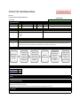
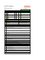
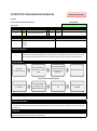
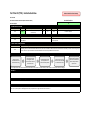
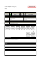
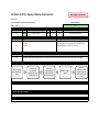
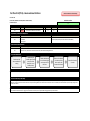
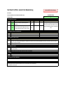
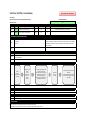
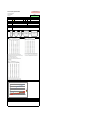
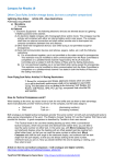
P14031 Test Plan Summary
Spec #
Metric/Specification
Units
Marginal
Target
S1
S2
S3
S4
S5
S6
S7
S8
S9
S10
S12
S13
S14
Transfer time
User reach distance to jib lines
Does design only contain mechanical parts?
Distance between existing bench and seat
Does design require boat modification?
Is fixture permanently fastened to boat?
Device Weight
Device displacement from secured position
Number of potential pinch points
User's unobstructed field of view (compared to no device use)
Does the user have the option to secure their limbs?
Time to get into seat
Time to get out of seat
sec
in
yes/no
mm
yes/no
yes/no
lbs
in
count
%
yes/no
min
min
5
25
Yes
200
No
No
100
2
5
75
Yes
5
5
2
15
Yes
minimize
No
No
50
0
0
100
Yes
2
2
↓
↓
X
↓
X
X
↓
↓
↓
↑
X
↓
↓
TP1
TP2
TP3
TP4
TP3
TP3
TP5
TP6
TP7
TP8
TP3
TP9
TP9
S15
Weight capacity
lbs
220
265
↑
TP10
S16
S17
S18
S19
S20
S21
S22
Are all components chosen for corrosion resistant properties?
Time to install device in Sonar
Number of installation steps
Max horizontal distance from boat centerline
Degrees of rotation
Vertical distance between seat and boom
Number of parts requiring specialized equipment to manufacture.
Number of custom parts used in design (custom parts cannot be purchased
'off-the-shelf' in a store or online)
Time to remove device from Sonar
Number of steps to uninstall device
% of users who find seat "comfortable"
Depth of plywood groove after 13500 rotations (~5 years)
yes/no
min
count
in
degrees
in
count
Yes
20
10
21
+/- 30
33
5
Yes
5
5
24
+/-45
38
0
X
↓
↓
↑
↑
↑
↓
TP3
TP11
TP11
TP12
TP13
TP14
TP15
count
5
0
↓
TP15
min
count
%
in
20
10
60
0.23
5
5
75
0.10
↓
↓
↑
↓
TP16
TP16
TP17
TP18
S23
S24
S25
S26
S27
KEY - TEST RESULTS
X
Δ
O
Does not meet expectation
Caution-Undetermined if specification is met
Meets specification
Direction Test Plan
Sonar
Needed
X
X
Sailing
Req'd
X
X
X
X
X
X
X
X
X
X
X
X
X
X
X
X
Actual
Concluded Condition
3 sec
19"
Yes
6" (152.4 mm)
No
No
51 lbs
0.75"
0, but there is 1 trip hazard
100%
Yes
dependent on disability
dependent on disability
O
O
O
O
O
O
O
O
O
O
O
Δ
Δ
215 lbs (ANSYS simulation shows failure at ~300 lbs,
but team could not test to device failure)
Δ
Yes
4.5 minutes
6 steps
23"
+/- 90
34.5"
1 part
O
O
O
O
O
O
O
1 part
X
X
X
2.5 minutes
6 steps
Mfgr chooses seat that fits needs
depth = 0.025 in
O
O
O
Δ
O
Test Plan # 1 (TP1) - Transfer time between port and starboard
Back to P14031 Test Plan Summary
Test Team:
Test Location:
Test Date:
I. TESTING SPECIFICATION
Specification Number
Risk
Specification
Units
Marginal Value
Target Value
Comments/Status
S1
LOW
Transfer time
sec
5
2
Cannot test until device is fully built
II. EQUIPMENT/CONDITIONS REQURIED
Specification Number
S1
Equipment or Instrumentation required
Completed Jib Transfer System
Sonar Sailboat
Stopwatch
Testing Conditions
Test under real sailing conditions - while on the water in order to obtain most accurate measurements.
If these conditions are not available then it is possible to complete the test while stationary (test will show
device does rotate; however, will provide unreliable results for transfer time conclusion)
III. DATA COLLECTION STRATEGY
Specification Number
S1
Data Acquisition Strategy
Conducting a time study will allow us to determine the time it takes to move the user between port and starboard. The transfer time is important because the user needs to be
able to switch sides relatively quickly to maintain the appropriate weight distribution.
IV. TESTING FLOWCHART
Gather required
instrumentation for
testing
Position user into the
jib transfer system
(position over bench
in locked position)
Before the tack, the
user will swing to the
other side; time this
motion
Record the time, in
seconds
V. RESULTS
The device was tested at a 15 degree heel angle and the results show approximately 3 second transfer time
VI. MITIGATION PLAN (IF NEEDED)
N/A
VII. CONCLUSION
The user will be able to transfer between port and starboard in an appropriate amount of time in order to maintain weight distribution
Repeat the time
measurement 10
times total
Test Plan # 2 (TP2) - Reach Distance to Jib Lines
Back to P14031 Test Plan Summary
Test Team: All
Test Location: Rochester Yacht Club (device installed in Sonar)
Concluded Condition
Test Date: 4/23/14
O
I. TESTING SPECIFICATION
Specification Number
Risk Level
Specification
Units
Marginal Value
Target Value
Comments/Status
S2
MED
User reach distance to jib lines
in
25
15
Cannot complete test until device is fully built
II. EQUIPMENT/CONDITIONS REQURIED
Specification Number
S2
Equipment or Instrumentation required
Completed Jib Transfer System
Sonar Sailboat
Tape Measure
Testing Conditions
None - Test can be completed while Sonar is out of water
III. DATA COLLECTION STRATEGY
Specification Number
S2
Data Acquisition Strategy
Measuring the maximum distance from the seat to the jib lines will allow the team to conclude that the jib system allows the user to reach the existing jib lines. We want the
distance the user has to reach, in order to hold the jib lines, to be comfortable and not cause an excessive strain on their body.
IV. TESTING FLOWCHART
Position the jib
transfer system
(position over
port-side bench in
locked position)
Gather required
instrumentation
for testing
Measure the
distance from the
edge of the seat
to the jib lines on
the bulkhead
Record the
distance, in inches
Unlock the seat
and swing to the
starboard side
(locking it in
position over the
bench)
V. RAW DATA ACQUISITION
Port-side locked position
Starboard locked position
Distance
19"
19"
VI. RESULTS
The distance for the user to access the jib lines is the same from both port and starboard locked positions, at 19"
VII. MITIGATION PLAN (IF NEEDED)
If the jib lines are not accessible by the user then the team can consider two options:
1) Moving the device more forward in the boat (if possible)
2) bringing the jib lines to the user by building another subsystem into the jib transfer system that feeds the existing jib lines within the user's reach
VIII. CONCLUSION
No mitigation action needed. The user is able to reach the jib lines from both port and starboard locked positions
Again, measure
the distance to
the jib lines and
record the
distance, in inches
Test Plan # 3 (TP3) - Yes/No Questions
Back to P14031 Test Plan Summary
Test Team: All
Test Location: Rochester Yacht Club (device installed in Sonar)
Concluded Condition
Test Date: 4/23/14
O
I. TESTING SPECIFICATION
Spec #
S3
Risk Level
Specification
LOW
Does design only contain mechanical parts?
Units
yes/no
Marginal Value
Yes
Target Value
Yes
Comments/Status
S5
LOW
Does design require boat modification?
yes/no
No
No
Able to test concurrently with TP1, when the system is installed in the Sonar
S6
LOW
Is fixture permanently fastened to boat?
yes/no
No
No
Able to prove concurrently with TP16, when the system is uninstalled from
the Sonar
S12
MED
Does the user have the option to secure their limbs?
yes/no
Yes
Yes
LOW
Are all components chosen for corrosion resistant
properties?
yes/no
Yes
Yes
S16
II. EQUIPMENT/CONDITIONS REQURIED
Corrosion testing on components not needed because using SS, aluminum,
and plastic. These materials are known to be corrosion resistant
S12
Equipment/Instrumentation/Material required
Completed BOM
None
None
Completed Jib Transfer System
'Ace' Bandage
Testing Conditions
N/A
N/A
N/A
Device needs to be stable to that the user can sit in the seat for testing
S16
Completed BOM
N/A
Spec #
S3
S5
S6
III. DATA COLLECTION STRATEGY
Spec #
S3
Data Acquisition Strategy
The jib transfer system will comply with ISAF/IFDS Regulations if there are no electronic components. Complying with these regulations allows for the device to be used in competitive sailing.
This test determines compliance with the ISAF/IFDS Regulations.
S5
The jib transfer system will comply with ISAF/IFDS Regulations if the device does not require modification of the Sonar (drilling into the boat, cutting into the boat, etc.) Complying with these
regulations allows for the device to be used in competitive sailing. This test determines compliance with the ISAF/IFDS Regulations.
S6
The jib transfer system will comply with ISAF/IFDS Regulations if the device is not permanently installed in the boat. By proving that the jib transfer system is removable from the Sonar, the
design will comply with this regulation. Complying with these regulations allows for the device to be used in competitive sailing. This test determines compliance with the ISAF/IFDS Regulations.
S12
S16
The purpose of this test is to confirm the device allows the user to secure their lower limbs, which they may not have full control of. If the user has the option to secure their legs to the base,
then the specification is met.
Corrosion testing
IV. TESTING PROCEDURE
S3
When the device is complete, check the BOM for electronic components. If there are none, the specification has been met
S5
When the device is installed into the Sonar, verify the installation process does not require any modifications to the Sonar. If there a no modifications, the specification has been met
S6
At the completion of TP16, the jib transfer system will be removed from the Sonar. The specification has been met when the device is removed from the Sonar.
After the device is installed in the Sonar, have a user sit in the seat and place their legs on the base (between the 2 PVC legs). Using an "Ace Bandage" see if the users legs are able to be secured
between the PVC leg supports. Record the result
When the components are purchased, ensure only the corrosion resitant material components are bought. If these materials are used, the specification has been met
S12
S16
V. RESULTS
S3
S5
S6
S12
S16
No electronic components on BOM
Installed in Sonar on 4/23/14 - no modifcations to Sonar needed for proper device fit & function
System was uninstalled from Sonar on 4/23/14 after testing - the device is not permanently fastened to the boat
User's legs are able to fit between the PVC arm assembly - Piers Park can chose to add a strap depending on the user's needs
All hardware components chosen with corrosion resistant properties
VI. MITIGATION PLAN (IF NEEDED)
S3
If there are electonic components in the BOM at completion, a note needs to be added to the instructional information that the device does not comply with sailing racing regulations. The jib
transfer system will not be allowed for the user in a race.
S5
If there are Sonar modifications required during installation, a note needs to be added to the instructional information that the device does not comply with sailing racing regulations. The jib
transfer system will not be allowed for the user in a race.
S12
If the device is permanently installed into the Sonar - and not able to be removed- a note needs to be added to the instructional information that the device does not comply with sailing racing
regulations. The jib transfer system will not be allowed for the user in a race.
N/A
S16
N/A
S6
VII. CONCLUSION
No mitigation action needed. All specifications for TP 3 are satisfied
Test Plan # 4 (TP 4) - Distance between bench and device seat
Back to P14031 Test Plan Summary
Test Team: All
Test Location: Rochester Yacht Club (device installed in Sonar)
Concluded Condition
Test Date: 4/23/14
O
I. TESTING SPECIFICATION
Specification Number
Risk Level
Specification
Units
Marginal Value
Target Value
S4
MED
Distance between existing bench and seat
mm
200
minimize
II. EQUIPMENT/CONDITIONS REQURIED
Specification Number
S4
Equipment or Instrumentation required
Completed base of system built
Sonar Sailboat
Tape Measure
Comments/Status
Testing Conditions
PVC chair needs to be assembled, but NOT glued together
III. DATA COLLECTION STRATEGY
Specification Number
S4
Data Acquisition Strategy
The jib transfer system will comply with ISAF/IFDS Regulations if the vertical distance between the existign Sonar bench seat and the jib transfer system seat is less than
200mm. Complying with these regulations allows for the device to be used in competitive sailing. This test determines compliance with the ISAF/IFDS Regulations.
IV. TESTING FLOWCHART
Gather required
instrumentation for testing
Position the jib transfer system
(position over bench in locked
position)
Measure the distance between
the top of the Sonar bench
and the bottom of the jib
transfer chair
Record the distance, in mm
To verify the measurement also complete the following:
Place the jib transfer system
on a flat surface
Measure the height from
the flat surface to the
bottom of the device's seat
Record the measurement, in
mm
Subtract the height of the
bench (mm)
V. RESULTS
Measurement from Sonar's existing bench seat to the top of the device's seat (where the user is seated) is ~6"
VI. MITIGATION PLAN (IF NEEDED)
If the height between the existing bench and the device seat is > 200mm then the team will not glue the PVC chair together. The team will re-evaluate the design to modify the height of the PVC chair. If
this is not possible, the device will still function but will not comply with the ISAF/IFDS Racing Regulations. If the device does not comply with the racing regulations, a note needs to be added to the
instructional information.
VII. CONCLUSION
The device complies with the ISAF/IFDS Regulations of being <200mm (~7.87 inches).
Complying with this regulation allows the assistive device to be used in competitive sailing
Test Plan # 5 (TP 5) - Weight of Jib Transfer System
Back to P14031 Test Plan Summary
Test Team: M. Brunelle, K. Wurman
Test Location: College of Engineering Machine Shop
Concluded Condition
Test Date: 4/28/14
O
I. TESTING SPECIFICATION
Specification Number
Risk Level
Specification
S7
MED
Device Weight
II. EQUIPMENT/CONDITIONS REQURIED
Specification Number
S7
Equipment or Instrumentation required
Completed System Assembled
Scale (lg enough to place system on)
Units Marginal Value
lbs
Target Value
100
Comments/Status
50
Testing Conditions
N/A
III. DATA COLLECTION STRATEGY
Specification Number
S7
Data Acquisition Strategy
Weighing the device will ensure that the customer requirement of "lightweight" has been met. Since the volunteers at Piers Park are responsible for installing/uninstalling the assitive devices, the weight is an important factor. If a device is too heavy then more volunteers are needed.
IV. TESTING PROCEDURE
When the device is completed, bring it to the KGCOE Machine Shop. Place the device on the scale and record weight, to the nearest pound. If the device is too large to place on the scale, the base
and seat will be weighed separately. The indiidual components will then be summed to obtain the overall system weight.
VI. RESULTS
Whole device fits on scale for measurement - Total system weight is 51 lbs
VII. MITIGATION PLAN (IF NEEDED)
N/A
VIII. CONCLUSION
The device weight of 51 lbs is significanly less than the previous project iteration.
With a total system weight of 51 lbs, two volunteers are needed to safely install and uninstall the device from the Sonar
Test Plan # 6 (TP 6) - Secure Device Fit in Sonar
Back to P14031 Test Plan Summary
Test Team: All
Test Location: Rochester Yacht Club (device installed in Sonar)
Concluded Condition
Test Date: 4/23/14
O
I. TESTING SPECIFICATION
Specification Number
Risk Level
Specification
Units Marginal Value
S8
MED
Device displacement from secured position
II. EQUIPMENT/CONDITIONS REQURIED
Specification Number
S8
Equipment or Instrumentation required
Completed System Assembled
Sonar Sailboat
Tape Measure
Video Camera
in
2
Target Value
Comments/Status
0
Testing Conditions
Device needs to be secured in a Sonar. The user will have a force applied to them in
order to measure the displacement of the system.
III. DATA COLLECTION STRATEGY
Specification Number
S8
Data Acquisition Strategy
The purpose of the test is determine how secure the jib transfer system fits in the Sonar. If the specification is met then the jib transfer systems was designed to the
appropriate Sonar dimensions and fits securely in the sailboat.
IV. TESTING FLOWCHART
Testing procedure for displacement of user and seat:
Gather required
instrumentation
for testing
Set up the video
camera for data
collection
Position the jib
transfer system
(position over
bench in locked
position)
Apply a force to
the user
Review the
video's frames
to determine
the maximum
displacement of
the seat
Record the
distance, in
inches
Have the user swing
to the other side
Observce the position
of the jib transfer
system's base after
the swing and any
displacement (from
sliding)
Record the distance,
in inches
Testing procedure for displacement of the device base:
Gather required
instrumentation for
testing
Position the jib
transfer system
(position over bench
in locked position)
Note the position of
the jib transfer
system's base
V. RESULTS
The device displaces 0.50"-0.75" from it's initial secured position
VI. MITIGATION PLAN (IF NEEDED)
If the device moves > 2 inches then the team will re-evaluate the design of the securing mechanism, finding a way to secure the device to the Sonar more effectively
VII. CONCLUSION
The device is secure in the Sonar and is safe for use
Test Plan # 7 (TP 7) - Pinch Points
Back to P14031 Test Plan Summary
Test Team: All
Test Location: Rochester Yacht Club (device installed in Sonar)
Concluded Condition
Test Date: 4/23/14
O
I. TESTING SPECIFICATION
Specification Number
Risk Level
Specification
Units
Marginal Value
Target Value
Comments/Status
S9
MED
Number of potential pinch points
count
5
0
Cannot test until device is complete
II. EQUIPMENT/CONDITIONS REQURIED
Specification Number
S9
Equipment or Instrumentation required
Completed Jib Transfer System
Sonar Sailboat
Testing Conditions
Device should be installed in the Sonar to accurately estimate pinch points in
the real use environment
III. DATA COLLECTION STRATEGY
Specification Number
S9
Data Acquisition Strategy
This ergonomic analysis will determine the relative safety of the device for the user - and others in the boat - based on the number of pinch points.
IV. TESTING PROCEDURE
After the jib transfer system is installed in the Sonar, count the number of pinch points that pose a safety hazard to the user. Develop countermeasures to reduce the severity or likeliood of
injury from these pinch points. Publish this information in the instruction manual.
V. RESULTS
Analysis shows no pinch points because the spring and all moving components are covered by the bases
The addition of handles to the bottom base did create one trip hazard (hazard for the user and the other people in the Sonar)
VI. MITIGATION PLAN (IF NEEDED)
N/A
VII. CONCLUSION
There is limited safety hazards for the user while using the device
The one trip hazard created by the handles on the bottom base will be outlined as a warning in the user manual
Test Plan # 8 (TP 8) - Unobstructed View
Back to P14031 Test Plan Summary
Test Team: All
Test Location: Rochester Yacht Club (device installed in Sonar)
Concluded Condition
Test Date: 4/23/14
O
I. TESTING SPECIFICATION
Specification Number
Risk Level
S10
LOW
Specification
Units Marginal Value
User's unobstructed field of view (compared to
%
75
no device use)
II. EQUIPMENT/CONDITIONS REQURIED
Specification Number
S10
Equipment or Instrumentation required
Complete jib transfer system
Sonar Sailboat
S10
Comments/Status
100
test after complete
Testing Conditions
Ideally want to test under sailing conditions, but it is possible to test with device
in a secure position
III. DATA COLLECTION STRATEGY
Specification Number
Target Value
Data Acquisition Strategy
By obtaining the user's estimated unobstructed field of view, the team will be able to determine if the device inhibts the user's ability to see their surroundings. The jib
trimmer is often the "eyes of the boat" and needs to be able to see as much as possible of their field of view
IV. TESTING PROCEDURE
Gather required
instrumentation and
materials for testing
Have user sit on the
existing bench of the
Sonar and note what is in
their field of view
Position the jib transfer
system (position over
bench in locked position)
Have the user sit in the
device seat and note what
is in their field of vision
*This is a subjective test and needs to be brainstormed further to see if another test is more suitable, or if the metric for the function needs to be changed
V. RESULTS
100% field of view is unobstructed (the user can see the same field of view they would have without the device)
VI. MITIGATION PLAN (IF NEEDED)
N/A
VII. CONCLUSION
The user has the same field of view they would have without the use of the device --> 100% of the user's field of view is unobstructed
** The user may actually have an advantage because they are positioned ~6" higher than if no device was used **
Estimate the % of field of
view that is unobstructed
while in the jib transfer
system seat*
Test Plan # 9 (TP9) - Getting into/out of the device
Back to P14031 Test Plan Summary
Test Team: All
Test Location: Rochester Yacht Club (device installed in Sonar)
Concluded Condition
Test Date: 4/23/14
Δ
I. TESTING SPECIFICATION
Spec #
S13
S14
Risk Level
Specification
LOW
Time to get into seat
LOW
Time to get out of seat
Units
min
min
II. EQUIPMENT/CONDITIONS REQURIED
Spec #
S13
S14
Equipment/Instrumentation/Material required
Completed Jib Transfer System
Sonar Sailboat
Stopwatch
Completed Jib Transfer System
Sonar Sailboat
Stopwatch
Marginal Value
5
5
Target Value
2
2
Comments/Status
Testing Conditions
Test under real sailing conditions - while on the water in order to obtain most accurate
measurements.
If these conditions are not available then it is possible to complete the test while stationary (test
will not consider the reduce stability of the Sonar while it is in the water, or in a hoist)
III. DATA COLLECTION STRATEGY
Spec #
Data Acquisition Strategy
S13
Conducting a time study will allow us to determine the time it takes to position a user into the seat. The entry time is important because the user wants to be able to easily begin using the
device. A lengthy process to set the user up in the seat may be discourgaing and take away the freedom associated with sailing
S14
Conducting a time study will allow us to determine the time it takes to position a release themselves from the seat. The exit time is important because the user wants to be able to easily
stop using the device. A lengthy process to get the user out of the seat may be discourgaing
IV. TESTING FLOWCHART
S13
Gather required
instrumentation for
testing
S14
Gather required
instrumentation for
testing
Position the jib transfer
system (position over
bench in locked position)
Position user into the
jib transfer system
(position over bench
in locked position)
Have the user stand on
the dock and board the
Sonar
Record the time, in
seconds, it takes the
user to get out of the
seat and unboard the
Sonar to the dock
Record the time, in
seconds it takes for the
user to board the Sonar
and correctly position
themselves in the device
Repeat the time
measurement 10
times total
V. RESULTS
Cannot complete test
VI. MITIGATION PLAN (IF NEEDED)
N/A
VII. CONCLUSION
The time it takes for the user to get in and out of the seat is fully dependent on the user's disabilities
The test team is able to get in and out of the seat in <<1 minute, which meets the specification
No testing was complete with disabled users; however, the team is confident that the user will be able to position themselves in the seat in the 2-5min range
Repeat the time
measurement 10 times
total
Test Plan # 10 (TP 10) - Weight Capacity
Back to P14031 Test Plan Summary
Test Team:
Test Location:
Test Date:
I. TESTING SPECIFICATION
Specification Number
Risk Level
Specification
S15
LOW
Weight capacity
Units Marginal Value
II. EQUIPMENT/CONDITIONS REQURIED
Specification Number
S15
Equipment or Instrumentation required
Sonar Sailboat
Weights - up to a combined 265 lbs
Tape Measure
lbs
Target Value
Comments/Status
265
cannot test until device is built
220
Testing Conditions
Jib Transfer System needs to be installed into the Sonar. If a Sonar is not
available for testing, then the device needs to be secured in position so that it is
able to ungergo testing
III. DATA COLLECTION STRATEGY
Specification Number
S15
Data Acquisition Strategy
Determining the weight capacity of the system is a key piece of information that needs to be included in the instructional manual. If the specification is met, then the
device is able to accommodate a wide range of users.
IV. TESTING FLOWCHART
Gather the
instrumentation and
materials needed
Set the jib transfer
system up in the
Sonar Sailboat
Place 50 lbs onto
the seat's center,
wait 2 minutes
measure the
deflection
V. RAW DATA ACQUISITION
ANSYS simulation shows device will fail at 260 lbs
The team cannot test the device to failure, but knows that it can hold at least 215 lbs
VI. RESULTS
VII. MITIGATION PLAN (IF NEEDED)
VIII. CONCLUSION
The device is able to accommodate a range of users, given that it can hold at least 215 lbs (most likely more given ANSYS analysis)
Place 50 more lbs
onto the seat's
center, wait 2
minutes
measure the
deflection
Record the total
weight on the
system and the total
deflection
keep loading the
seat every 2 minutes
until the 220-265
range is met
Test Plan # 11 (TP11) - Installation of Jib Transfer System
Back to P14031 Test Plan Summary
Test Team: All
Test Location: Rochester Yacht Club (device installed in Sonar)
Concluded Condition
Test Date: 4/23/14
O
I. TESTING SPECIFICATION
Spec #
Risk Level
Specification
Units
Marginal Value
Target Value
S17
LOW
Time to install device in Sonar
min
20
5
S18
LOW
Number of installation steps
count
10
5
II. EQUIPMENT/CONDITIONS REQURIED
Spec #
S17
S18
Equipment/Instrumentation/Material required
Completed Jib Transfer System
Sonar Sailboat
Volunteers
Comments/Status
The assumption is a device with a fewer number of steps will be easier for
the user to install in the sailboat
Testing Conditions
Testing should occur while the Sonar is docked on the water (or in a hoist) in order to
represent real installation conditions. The volunteers used for testing will have limited to no
knowledge of the device to represent the volunteers at Piers Park who may have no existing
knowledge.
None
None
III. DATA COLLECTION STRATEGY
Spec #
S17
S18
Data Acquisition Strategy
Conducting a time study, with multiple users, to obtain the average time it takes for two individuals to properly install the device in the Sonar will allow the team to evaulate the ease of
installation.
Determining the number of steps in the installation manual will allow the team to evaluate the ease of installation.
IV. TESTING FLOWCHART
Gather required
instrumentation for
testing
S17
S18
Place all system
components on the
dock next to the Sonar
Time how long it takes
for the 2 volunteers to
follow the instruction
manual to properly
install the device in
the Sonar
Count the number of steps in the completed installation manual and record the number
V. RESULTS
S17
S18
4.5 minutes
6 steps
VI. MITIGATION PLAN (IF NEEDED)
S17
S18
N/A
N/A
VII. CONCLUSION
The device is easy to install, requiring < 5 minutes for 2 people to complete the installation process.
It is not possible to install the device with less than 2 people due to the size
The instruction manual clearly states in 6 steps how to properly install the system into the Sonar
Record the time, in in
minutes
Repeat the time
measurement 5 total
times (ideally using
different volunteers
for each test to
elimintae learning
curve effect)
Test Plan # 12 (TP 12) - Max User Distance from Centerline
Back to P14031 Test Plan Summary
Test Team: All
Test Location: Rochester Yacht Club (device installed in Sonar)
Concluded Condition
Test Date: 4/23/14
O
I. TESTING SPECIFICATION
Specification Number
Risk Level
Specification
S19
LOW
Max horizontal distance from boat centerline
Units Marginal Value
in
II. EQUIPMENT/CONDITIONS REQURIED
Specification Number
S19
Equipment or Instrumentation required
Completed Jib Transfer System
Sonar Sailboat
Masking Tape
Measuring Tape
21
Target Value
Comments/Status
24
Testing Conditions
The device needs to be properly installed in the Sonar, but the Sonar does not
need to be on the water.
III. DATA COLLECTION STRATEGY
Specification Number
S19
Data Acquisition Strategy
The distance that the user is able to move to from the centerline is important because the user needs to be able to maintain the appropriate weight distribution. Jib
Trimmers who do not need assistive devices are able to place themselves past the bench seats (seating themselves on the edge of the Sonar). If the specification is met,
then the jim trimmer in the device will be able to provide sufficient weight distribution.
IV. TESTING FLOWCHART
Gather required
instrumentation
for testing
Place a piece of
masking tape at
the centerline of
the sonar, as a
reference
Position the jib
transfer system
(position over
bench in locked
position)
V. RAW DATA ACQUISITION
X
X
VI. RESULTS
23" distance between centerline and back of seat (when positioned over the bench)
VII. MITIGATION PLAN (IF NEEDED)
N/A
VIII. CONCLUSION
The jib trimmer can provide sufficient weight distribution while using the device
Place a piece of
masking tape on
the bench, at the
back of the device
seat
measure the
horizontal
distance between
these two pieces
of tape
subtract 1/2 the
depth of the
device seat (to
obtain the
distance in
relation to the
center of the seat)
Repeat with the
device over the
other Sonar
bench
Test Plan # 13 (TP13) - Degrees of Rotation from Centerline
Back to P14031 Test Plan Summary
Test Team: All
Test Location: Rochester Yacht Club (device installed in Sonar)
Concluded Condition
Test Date: 4/23/14
O
I. TESTING SPECIFICATION
Specification Number
Risk Level
Specification
Units
Marginal Value
Target Value
Comments/Status
S20
LOW
Degrees of rotation
degrees
+/- 30
+/-45
cannot test until device is built
II. EQUIPMENT/CONDITIONS REQURIED
Specification Number
S20
Equipment or Instrumentation required
Completed Jib Transfer System
Sonar Sailboat
Tape Measure
Testing Conditions
Device needs to be installed in the Sonar; however, the Sonar does not need to
be in the water. If a Sonar is not available for testing, then the test can be
conducted knowing the internal dimensions of the Sonar
III. DATA COLLECTION STRATEGY
Specification Number
S20
Data Acquisition Strategy
Determining the degrees of rotation will allow the team to conclude that there is a large range of movement for the jib trimmer while using the assistive device.
IV. TESTING FLOWCHART
Gather required
instrumentation for
testing
Position the jib
transfer system
(position over bench
in locked position)
VI. RESULTS
Device can swing +/- 90 degrees from the centerline of the boat
VII. MITIGATION PLAN (IF NEEDED)
N/A
VIII. CONCLUSION
There is a large range of motion for the jib trimmer while using the assistive device
measure the
maximum angle of
rotation from the
initial seat centerline
Record the angle, in
degrees
Repeat the
measurement with
the seat secured on
the other side of the
Sonar
Test Plan # 14 (TP14) - Boom and Head Collision
Back to P14031 Test Plan Summary
Test Team: All
Test Location: Rochester Yacht Club (device installed in Sonar)
Concluded Condition
Test Date: 4/23/14
O
I. TESTING SPECIFICATION
Specification Number
Risk Level
Specification
S21
HIGH
Vertical distance between seat and boom
Units Marginal Value
in
33
II. EQUIPMENT/CONDITIONS REQURIED
Specification Number
S21
Equipment or Instrumentation required
Completed Jib Transfer System
Sonar Sailboat
Measuring Tape
Target Value
Comments/Status
38
Testing Conditions
Device needs to be installed in the Sonar and the boom needs to be positioned
at its lowest point (directly down the centerline of the sailboat)
III. DATA COLLECTION STRATEGY
Specification Number
S21
Data Acquisition Strategy
Determining the vertical distance between the device seat and boom will determine the likelihood that the user's head will come in contact with the boom. If the
specification is met, then the user should not have to worry about the boom hitting their head.
IV. TESTING PROCEDURE
Gather required
instrumentation for
testing
Position the jib
transfer system at the
centerline of the
Sonar(this is not a
locked position)
Position the boom to
the minimum height
at the centerline of
the Sonar
Measure the distance
from the top of the
device seat to the
bottom of the boom
Record this distance,
in inches
V. RESULTS
Height between the seat top (where the user sits) and the boom is 34.5"
VI. MITIGATION PLAN (IF NEEDED)
If there is not enough distance between the boom and the device seat, there is a high probability that the boom will hit the user in the head. This is a big safety concern. In order to reduce the
likelihood or severity of this hazard the team will need to incorporate warning labels on the device and in the instruction manual. In addition, the team will evaluate any minor design changes that
could reduce this hazard.
VII. CONCLUSION
Most users should not have to worry about the hitting their head on the boom as they transfer
The user should still be aware of what is going on around them to ensure they are not injured while swinging between port and starboard
Test Plan # 15 (TP15) - Custom Parts Manufacturing
Back to P14031 Test Plan Summary
Test Team: All
Test Location: Rochester Yacht Club (device installed in Sonar)
Concluded Condition
Test Date: 4/23/14
O
I. TESTING SPECIFICATION
Spec #
Risk Level
Specification
S23
LOW
Number of parts requiring specialized equipment to
manufacture.
S24
LOW
Number of custom parts used in design (custom parts
cannot be purchased 'off-the-shelf' in a store or online)
Units
Marginal Value
Target Value
Comments/Status
count
5
0
count
5
0
Testing will occur periodically throughout the build
phase. As parts are built, notes will be taken on the
number of manufacturing processes and equipment
used
II. EQUIPMENT/CONDITIONS REQURIED
Spec #
S23
S24
Equipment/Instrumentation/Material required
Completed Jib Transfer System
None
Testing Conditions
None
None
III. DATA COLLECTION STRATEGY
Spec #
Data Acquisition Strategy
S23
The number of parts requiring specilized equipment to manufacture will relate to the ease of assembly, repdroduction, and cost. As the number increases these customer
needs are less likely to be satisfied.
S24
Count number of parts that require more than 4 processes to manufacture.
IV. TESTING PROCEDURE
S23
S24
Count the numer of parts that require specialized equipment to manufacture (specialized equipment is considered to be tools/machinery that the average person would not
have in their posession).
Count the number of parts that require more than 4 processes to manufacture.
V. RESULTS
S23
S24
1 part
1 part
VI. MITIGATION PLAN (IF NEEDED)
N/A
VII. CONCLUSION
The device only has one custom part that will need to be taken to a local machine shop for manufacturing
The specifications for TP15 are met
Test Plan # 16 (TP16) - Un-installation
Back to P14031 Test Plan Summary
Test Team: All
Test Location: Rochester Yacht Club (device installed in Sonar)
Concluded Condition
Test Date: 4/23/14
O
I. TESTING SPECIFICATION
Spec #
Risk Level
Units
Marginal Value
Target Value
Comments/Status
S24
LOW
Time to remove device from Sonar
Specification
min
20
5
Testing should occur after TP11 is complete
S25
LOW
Number of steps to uninstall device
count
10
5
II. EQUIPMENT/CONDITIONS REQURIED
Spec #
S24
S25
Equipment/Instrumentation/Material required
Completed Jib Transfer System
Sonar Sailboat
Volunteers
Testing Conditions
Testing should occur while the Sonar is docked on the water (or in a hoist) in order to
represent real installation conditions. The volunteers used for testing will have limited to
no knowledge of the device to represent the volunteers at Piers Park who may have no
existing knowledge.
None
None
III. DATA COLLECTION STRATEGY
Spec #
S24
S25
Data Acquisition Strategy
Conducting a time study, with multiple users, to obtain the average time it takes for two individuals to properly uninstall the device in the Sonar will allow the team to evaulate the
ease of un-installation.
Determining the number of steps in the installation manual will allow the team to evaluate the ease of un-installation.
IV. TESTING FLOWCHART
Gather
required
instrumentatio
n for testing
S24
S25
Position the jib
transfer
system
(position over
bench in
locked
position)
Time how long it takes for the 2
volunteers to follow the
instruction manual to properly uninstall the device in the Sonar
(completely removing the
components from the Sonar and
placing them on the dock)
Count the number of steps in the completed installation manual for the process of removing the device from the Sonar, and record the number
V. RESULTS
2.5 minutes
6 steps
S24
S25
VI. MITIGATION PLAN (IF NEEDED)
S24
S25
Record the
time, in in
minutes
N/A
N/A
VII. CONCLUSION
The device is easy to un-install, requiring < 5 minutes for 2 people to complete the process.
It is not possible to un-install the device with less than 2 people due to the size
The instruction manual clearly states in 6 steps how to properly remove the system from the Sonar
Repeat the time measurement 5
total times
(ideally using different volunteers
for each test to elimintae learning
curve effect)
Test Plan # 17 (TP17) - Comfort
Back to P14031 Test Plan Summary
Test Team:
Test Location:
Concluded Condition
Test Date:
Δ
I. TESTING SPECIFICATION
Specification Number
Risk Level
Specification
Units
Marginal Value
Target Value
S26
LOW
% of users who find seat "comfortable"
%
60
75
II. EQUIPMENT/CONDITIONS REQURIED
Specification Number
Equipment or Instrumentation required
Completed Jib Transfer System
S26
Comments/Status
Testing Conditions
Ideally, would like the device installed in a Sonar. However, testing is possible as
long as the device is properly secured to allow a user to place their weight on the
seat
III. DATA COLLECTION STRATEGY
Specification Number
S26
Data Acquisition Strategy
This survey of "comfort" will evaluate whether the device can accommodate multiple users. If a wide audience is surveyed, and a large percentage find the seat
"comfortable" then the specification has been met.
IV. TESTING FLOWCHART
Ask for volunteers to sit in the device and rate their relative comfort on a scale of 1-10. Record the results, and analyze the data.
V. RAW DATA ACQUISITION
VI. RESULTS
VII. MITIGATION PLAN (IF NEEDED)
If there are volunteers who do not find the device comfortable, the team will solicit their feedback on what would increase their comfort. These suggestions will be considered for potential (small scale)
design changes
VIII. CONCLUSION
The seat is installed to the seat plate, so the person building the device can pick a seat that best suits their needs
Test Plan # 18 (TP18) - Plywood Base Lifetime
Back to P14031 Test Plan Summary
Test Team: Matt Brunelle, Mike Kennedy
Test Location: ME Machine Shop
Test Outcome
Test Date: 2/11/14
O
I. TESTING SPECIFICATION
Specification Number
S27
Risk Level
Specification
Units
Marginal Value
MED
Depth of plywood groove after 13500 rotations (~5 years)
in
0.23
II. EQUIPMENT/CONDITIONS REQURIED
Specification Number
S27
Target Value
0.10
Comments/Status
Testing will be done by applying a constant load to the plywood
test sample with the lathe running to estimate lifetime of the
plywood under braking.
Equipment or Instrumentation required
Testing Conditions
Plywood test sample
Lathe with with four-jaw chuck
Plywood sample must be secured in chuck so it will not move relative to the
chuck during the test.
III. DATA COLLECTION STRATEGY
Data Acquisition Strategy
Specification Number
Time and lathe speed will be measured to estimate usage lifetime
S27
IV. TESTING FLOWCHART
Secure test
sample in
chuck.
Prepare lathe
and chuck.
Apply load to cross-slide handle
to provide a constant pressure
to the test sample and begin
recording time.
Start
lathe.
Stop lathe and time measurment when
a 1/4 inch 'groove' has been cut into the
plywwod sample.
V. RAW DATA ACQUISITION
TEST #1
TEST #2
VI. RESULTS
Comparison of Groove Test Depths
Average Groove Depth (in)
0.120
0.100
0.080
Test 1
0.060
Test 2
0.040
Test 3
0.020
0.000
0
10
20
30
40
50
60
70
80
90
Time (min)
VII. MITIGATION PLAN (IF NEEDED)
N/A
VIII. CONCLUSION
The groove depth at 13,500 cycles (~5 sailing seasons) was 0.116in. This shows the plywood can withstand the braking mechanism for the duration of the device's use