1
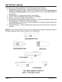
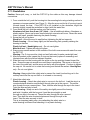
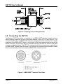
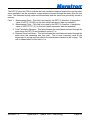
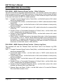
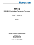
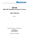
DST110 NMEA 2000® Depth/Speed/Temperature Transducer User’s Manual Revision 1.2 Copyright © 2014 Maretron, LLP All Rights Reserved Maretron, LLP 9014 N. 23rd Ave #10 Phoenix, AZ 85021-7850 http://www.maretron.com Maretron Manual Part #: M003005 Revision 1.2 Page i DST110 User’s Manual Revision History Revision Description 1.0 Original document 1.1 Typographical corrections Added configurable items to configuration section 1.2 Removed stainless steel housing information Added clarifications on hole saw sizes Added transmission power specification Page ii Revision 1.2 Table of Contents 1 2 3 4 5 6 7 8 9 10 11 General ............................................................................................................................. 1 1.1 Introduction................................................................................................................1 1.2 Features ....................................................................................................................1 1.3 Quick Install ...............................................................................................................1 Installation ......................................................................................................................... 2 2.1 Unpacking the Box ....................................................................................................2 2.2 Housing Material........................................................................................................2 2.3 Tools and Materials ...................................................................................................2 2.4 Pretest .......................................................................................................................3 2.5 Antifouling Paint ........................................................................................................3 2.6 Choosing a Mounting Location ..................................................................................3 2.7 Mounting the DST110................................................................................................5 2.7.1 All Hull Types Except Cored Fiberglass .....................................................5 2.7.2 Installation in a Cored Fiberglass Hull ........................................................7 2.8 Connecting the DST110 ............................................................................................8 2.8.1 Checking Connections................................................................................9 Transducer Depth Offset Calibration ................................................................................. 9 Temperature Offset Calibration ....................................................................................... 10 Speed Multiplier Calibration ............................................................................................ 10 Zeroing the Cumulative Voyage Distance (Log) .............................................................. 10 Maintenance ................................................................................................................... 10 7.1 Using the Blanking Plug .......................................................................................... 10 7.2 Servicing the Insert .................................................................................................. 11 7.3 Replacement Parts .................................................................................................. 12 7.4 Connection Checking .............................................................................................. 12 7.5 Antifouling Paint ...................................................................................................... 12 Troubleshooting .............................................................................................................. 12 Technical Specifications.................................................................................................. 13 Technical Support ........................................................................................................... 14 Maretron (2 Year) Limited Warranty ................................................................................ 15 Table of Figures Figure 1 – Antifouling Paint Application ..................................................................................... 3 Figure 2 – Mounting Locations .................................................................................................. 4 Figure 3 – Bedding and Installation ........................................................................................... 5 Figure 4 – Preparing a Cored Fiberglass Hull............................................................................ 8 Figure 5 – NMEA 2000® Connector Face Views ....................................................................... 8 Figure 6 – Replacing the Paddlewheel and O-rings ................................................................ 11 Figure 7 – Troubleshooting Guide ........................................................................................... 12 Table of Appendices Appendix A – NMEA 2000® Interfacing.................................................................................... A1 Revision 1.2 Page iii DST110 User’s Manual This page intentionally left blank Page iv Revision 1.2 1 General 1.1 Introduction Congratulations on your purchase of the Maretron DST110 NMEA 2000® Depth, Speed, and Temperature Transducer. Maretron has designed and built your transducer to the highest standards for years of dependable and accurate service. The DST110 detects the water depth with a 235 KHz depth transducer, the water speed with a paddlewheel and Hall effect sensor, and the water temperature with a precision thermistor element. The Maretron DST110 is designed to operate within the harsh demands of the marine environment. However, no piece of marine electronic equipment can function properly unless installed, calibrated, and maintained in the correct manner. Please read carefully and follow these instructions for installation, calibration, and usage of the Maretron DST110 in order to ensure optimal performance. 1.2 Features The Maretron DST110 NMEA 2000® Depth/Speed/Temperature Transducer has the following features. NMEA 2000® Interface 235 KHz Ceramic Transducer for Detecting Water Depth 100 Watt RMS Power Output for Depth Measurements up to 100 meters Paddlewheel with Hall Effect Sensor for Detecting Speed Through Water Advanced Digital Signal Processing for Accurate Speed Indication Down to 1 Knot Total Cumulative Distance (distance traveled through the water since installation) Cumulative Voyage Distance (distance traveled through the water since last reset) Precision Thermistor for Detecting Water Temperature Calibration for Compensating Transducer Offset to Waterline or Keel Calibration for Compensating Temperature Offset Calibration for Compensating Speed Through Water Waterproof Enclosure and Cable System 1.3 Quick Install Installing the Maretron DST110 transducer involves the following five steps. Please refer to the individual sections for additional details. 1. 2. 3. 4. 5. 6. 7. Unpack the Box (Section 2.1) Choose a Mounting Location (Section 2.6) Mount the DST110 Transducer (Section 2.7) Connect the DST110 Transducer (Section 2.8) Calibrate the DST110 Transducer for Waterline or Keel Offset (Section 3.2) (Optional) Calibrate the DST110 Transducer for Temperature Offset (Section 3.3) (Optional) Calibrate the DST110 Transducer Speed Multiplier (Section 3.4) Revision 1.2 Page 1 DST110 User’s Manual 2 Installation 2.1 Unpacking the Box When unpacking the box containing the Maretron DST110, you should find the following items. 1 – DST110 Insert (with attached cable) 1 – Plastic Housing 1 – Plastic Hull Nut 1 – Rubber Bushing 1 – Safety Wire 1 – Blanking Plug 1 – Tube of Silicone Lubricant 1 – Instructions and O-ring for Non-Valve Housings 1 – DST110 User’s Manual 1 – Warranty Registration Card If any of these items are missing or damaged, please contact Maretron. 2.2 Housing Material The DST110 is supplied with a plastic housing that is suitable for most installations. As an option, Maretron offers both a bronze housing material. Please follow these recommendations for determining the right material for your particular installation. Plastic housing recommended for fiberglass or metal hulls only. Never install a plastic housing in a wood hull since swelling of the wood may overstress the plastic causing a fracture. Bronze housing recommended for fiberglass or wood hulls. Never mount a bronze housing in an aluminum hull because electrolytic corrosion will occur. Never install a metal housing in a vessel with a positive ground system. 2.3 Tools and Materials Water-based antifouling paint (mandatory in salt water) Safety goggles Dust mask Electric drill with 10 mm (3/8”) or larger chuck capacity Drill bit: 3 mm or 1/8” Hole saw: 51 mm or 2” (plastic or bronze housing) Countersink tool (for installing a flush housing) Sandpaper Mild household detergent or weak solvent (such as alcohol) File (for installation in a metal hull) Marine sealant Additional washer [for aluminum hull less than 6 mm (1/4”) thick] Page 2 Revision 1.2 Slip-joint pliers (for installing a bronze housing) Zip-ties Installation in a cored fiberglass hull (see Section 2.7.2): o Hole saw for hull interior 60 mm or 2-3/8” o Fiberglass cloth and resin o or Cylinder, wax, tape, and casting epoxy. 2.4 Pretest Connect the DST110 to the NMEA 2000® network and spin the paddlewheel. Check for a speed reading and the approximate air temperature. If there is no reading or it is inaccurate, return the instrument to the place of purchase. 2.5 Antifouling Paint Marine growth can accumulate rapidly on the transducer’s surface reducing performance within weeks. Surfaces exposed to salt water must be coated with antifouling paint. Use water-based antifouling paint only. Never use ketone-based paint, since ketones can attack many plastics possibly damaging the sensor. It is easier to apply antifouling paint before installation, but allow sufficient drying time. Reapply paint every 6 months or at the beginning of each boating season. Paint the following surfaces (see Figure 1): Outside wall of the insert below the lower O-ring Exposed end of the insert Paddlewheel cavity Paddlewheel Exterior lip of the housing Bore of the housing up 30 mm (1-1/4”) Blanking plug below the lower O-ring including the exposed end Figure 1 – Antifouling Paint Application 2.6 Choosing a Mounting Location The selection of a suitable mounting location is important for the optimal performance of the Maretron DST110. The mounting location and orientation of the DST110 should be: 1. Preferably on the starboard side of the hull —where propeller blades are moving downward through the water. 2. Continuously Immersed In Water 3. Where Water Flowing across the Hull is Smooth with a Minimum of Bubbles and Turbulence – especially at high speeds. 4. Where the Transducer Beam is Unobstructed by the Keel or Propeller Shaft(s) 5. Where there is a Minimum Deadrise Angle 6. Accessible from Inside the Vessel – with adequate headroom for the height of the housing, tightening the nuts, and removing the insert. Allow a minimum of 280 mm (11”). Revision 1.2 Page 3 DST110 User’s Manual Please follow the following guidelines for different hull types (see Figure 2): 1. Displacement Hull Powerboats – Locate amidships near the centerline. 2. Planing Hull Powerboats – Mount well aft, on or near the centerline, and well inboard of the first set of lifting strakes to ensure that the DST110 is in contact with the water at high speeds. 3. Outboard and I/O – Mount just forward of the engine(s). 4. Inboard – Mount well ahead of the propeller(s) and shaft(s). 5. Step-hull – Mount just ahead of the first step. 6. Boat capable of speeds above 25 knots (29 MPH) – Review the installation location and operating results of similar boats before proceeding. 7. Fin Keel Sailboats – Mount on or as close as possible to the centerline and forward of the fin keel 300 to 600 mm (1 to 2’). 8. Full Keel Sailboats – Locate amidships and away from the keel at the point of minimum deadrise. Caution: Do not mount the DST110 in an area of turbulence or bubbles: near water intake or discharge openings; behind strakes, fittings, or hull irregularities. Figure 2 – Mounting Locations Page 4 Revision 1.2 2.7 Mounting the DST110 The Maretron DST110 is mounted through the hull. If the hull is a cored fiberglass hull, please follow the instructions in Section 2.7.2. For other hull types, please follow the instructions in Section 2.7.1. 2.7.1 All Hull Types Except Cored Fiberglass 2.7.1.1Hole Drilling Warning: Always wear safety goggles and a dust mask. 1. Drill a 3 mm or 1/8” pilot hole from inside the hull. If there is a rib, strut, or other hull irregularity near the selected mounting location, drill from the outside. 2. Using the 51 mm or 2” hole saw, cut a hole from outside the hull. Flush housing – Use a countersink tool to make a “seat” in the hull. 3. Sand and clean the area around the hole, inside and outside, to ensure that the sealant will adhere properly to the hull. If there is any petroleum inside the hull, remove it with either mile household detergent or a weak solvent (alcohol) before sanding. Metal hull – Remove all burrs with a file and sandpaper. 2.7.1.2Bedding Apply a 2 mm (1/16”) thick layer of marine sealant around the lip of the housing that contacts the hull and up the sidewall of the housing. The sealant must extend 6 mm (1/4”) higher than the combined thickness of the hull, washer(s), and hull nut (see Figure 3). This will ensure there is sealant in the threads to seal the hull and hold the hull nut securely in place. Figure 3 – Bedding and Installation Revision 1.2 Page 5 DST110 User’s Manual 2.7.1.3Installation Caution: Never pull, carry, or hold the DST110 by the cable as this may damage internal connections. 1. From outside the hull, push the housing into the mounting hole using a twisting motion to squeeze out excess sealant (see Figure 3). Align the arrow on the lip of housing to point forward toward the bow. If the DST110 is not installed on the centerline, angle the housing slightly toward the centerline to align it with the water flow. 2. From inside the hull, slide the washer onto the housing. Aluminum hull less than 6 mm (1/4”) thick – Use an additional rubbery, fiberglass, or plastic washer. Never use bronze since electrolytic corrosion will occur. Never use wood since it will swell, possible fracturing the plastic housing. 3. Screw the hull nut in place. Wood hull – Allow the wood to swell before tightening the hull nut securely. Plastic housing – Do not clamp tightly on the wrenching flats, possibly causing the housing to fracture. Plastic hull nut – Hand-tighten only. Do not over tighten. Metal hull nut-- Tighten with slip-joint pliers. 4. Remove any excess sealant on the outside of the hull to ensure smooth water flow over the DST110. Warning: The O-rings must be intact and well lubricated to make a watertight seal. 5. After the sealant cures, inspect the O-rings on the insert (replace if necessary) and lubricate them with the silicone lubricant supplied. 6. Slide the insert into the housing with the arrow on the top pointing forward toward the bow. Screw the cap nut several turns until there is resistance. The arrow on the top of the insert, the cable exit, and the arrow on the lip will all be aligned. Continue to tighten the cap nut. Be careful not to rotate the housing and disturb the sealant. Hand tighten only. Do not over tighten. Warning: Always attach the safety wire to prevent the insert from backing out in the unlikely event that the cap nut fails or is screwed on incorrectly. 7. Attach the safety wire. Plastic housing – Attach the safety wire to one eye in the hull nut. Load the wire in a counterclockwise direction and thread it through one eye in the cap nut. Thread the wire through the eye a second time. Then, lead the wire through the eye in the insert. Twist the wire securely to itself. Metal housing—Wrap one end of the safety wire tightly around the housing and twist it together with the long end. Lead the wire straight up and through one eye in the cap nut. Thread the wire through the eye a second time. Then lead the wire counterclockwise and through the eye in the insert. Twist the wire securely to itself. This is an important safety step, since attaching the safety wire to a metal housing is different than attaching it to a plastic housing. Page 6 Revision 1.2 8. Route the cable to the network being careful not to tear the cable jacket when passing it through the bulkhead(s) and other parts of the boat. Coil any excess cable and secure it in place with zip-ties to prevent damage. 2.7.1.4Checking for Leaks Warning: Never install a thru-hull transducer and leave the boat in the water unchecked for several days. When the boat is placed in the water, immediately check around the thru-hull transducer for leaks. Note that very small leaks may not be readily observed. It is best not to leave the boat in the water for more than 3 hours before checking it again. If there is a small leak, there may be considerable bilge water accumulation after 24 hours. If a leak is observed, repeat “Bedding” and “Installing” immediately (see Sections 2.7.1.2 and 2.7.1.3). 2.7.2 Installation in a Cored Fiberglass Hull The core (wood or foam) must be cut and sealed carefully. The core must be protected from water seepage, and the hull must be reinforced to prevent it from crushing under the hull not allowing the housing to become loose. Warning: always wear safety goggles and a dust mask. 1. Drill a 3 mm or 1/8” pilot hole from inside the hull. If there is a rib, strut, or other hull irregularity near the selected mounting location, drill from the outside. (If the hole is drilled in the wrong location, drill a second hole in a better location. Apply masking tape to the outside of the hull over the incorrect hole and fill it with epoxy.) 2. Using a 51 mm or 2” hole saw, cut the hole from outside the hull through the outer skin only (See Figure 4). 3. From inside the hull, use a 60 mm or 2-3/8” hole saw to cut through the inner skin and most of the core. The core material can be very soft. Apply only light pressure to the hole saw after cutting through the inner skin to avoid accidentally cutting the outer skin. 4. Remove the plug of core material so the inside of the outer skin and the inner core of the hull are fully exposed. Sand and clean the inner skin, core, and the outer skin around the hole. Caution: Completely seal the hull to prevent water seepage into the core. 5. If you are skilled with fiberglass, saturate a layer of fiberglass cloth with a suitable resin and lay it inside the hole to seal and strengthen the core. Add layers until the hole is the correct diameter. Alternatively, a hollow or solid cylinder of the correct diameter can be coated with wax and taped in place. Fill the gap between the cylinder and hull with casting epoxy. After the epoxy has set, remove the cylinder. 6. Sand and clean the area around the hole, inside and outside, to ensure that the sealant will adhere properly to the hull. If there is any petroleum residue inside the hull, remove it with either mild household detergent or a weak solvent (alcohol) before sanding. 7. Proceed with “Bedding” and “Installing” (see Sections 2.7.1.2 and 2.7.1.3). Revision 1.2 Page 7 DST110 User’s Manual Figure 4 – Preparing a Cored Fiberglass Hull 2.8 Connecting the DST110 The Maretron DST110 provides a connection to an NMEA 2000® interface through a five pin male connector located on the end of the cable attached to the DST110 (see Figure 5). You connect the DST110 to an NMEA 2000® network by plugging the male connector into a female receptacle of the NMEA 2000® network (note the key on the male connector and keyway on the female connector). Be sure the cable is connected securely and that the collar on the cable connector is tightened firmly. The DST110 is designed such that you can plug or unplug it from an NMEA 2000® network while the power to the network is connected or disconnected. Please follow recommended practices for installing NMEA 2000® network products. Figure 5 – NMEA 2000® Connector Face Views Page 8 Revision 1.2 2.8.1 Checking Connections Once the NMEA 2000® connection to the Maretron DST110 have been completed, check to see that speed, depth, and temperature information is being properly transmitted by observing an appropriate display. Refer to Section 5, “Troubleshooting”, if no heading information appears, otherwise proceed to Section 3 entitled “Configuring the DST110”. 3 Configuring the DST110 Several parameters of the DST110 are user-programmable. You configure the DST110 using Maretron N2KAnalyzer® software or a Maretron DSM150/DSM250 display or other NMEA 2000® display unit that is capable of configuring the DST110. Please refer to the Maretron N2KAnalyzer User’s Manual, DSM150 User’s Manual, or DSM250 User’s Manual, as appropriate, for details. users with direct access to the NMEA 2000® interface can perform transducer offset calibration directly through the NMEA 2000 ® interface (see Appendix A). 3.1 Advanced Configuration 3.1.1 Device Instance NMEA 2000® provides a unique device instance for each class of device on a vessel. This value should be programmed in each DST110 so that each DST110 is associated with a unique device instance number. The default instance number is 0, which is used to indicate the first DST110 that is connected to the network. Other DST110’s or devices transmitting similar information would be numbered 1, 2, and so on. The device instance number is used for parameters sent via the PGN 128267 Water Depth, PGN 128259 Speed, PGN130310 Environmental Parameters, and PGN 128275 Distance Log messages. 3.1.2 Instance Temperature The temperature instance is used to distinguish this DST110 from other devices on the network transmitting the same data. The Temperature Instance is used for parameters send via the PGN 130311 Environmental Parameters and PGN 130312 Temperature messages. 3.1.3 Installation Description You can configure the two installation description parameters with any text you wish. Examples include date of installation, location, etc. NMEA 2000 diagnostic tools such as Maretron N2KAnalyzer® can display this information. 3.1.4 NMEA2000 PGN Enable/Disable The DST110 is capable of transmitting many different kinds of NMEA 2000 ® messages (or PGNs) associated with depth, speed, and temperature. You may individually enable or disable each of these messages. 3.2 Transducer Depth Offset Calibration The DST110 measures the depth of the water from the transducer, which may or may not be the waterline depth or the depth of water underneath the keel depending on the mounting location. Fortunately, the DST110 can be calibrated for reporting the offset from the transducer to the Revision 1.2 Page 9 DST110 User’s Manual waterline or the DST110 can be calibrated to report the offset between the transducer and the lowest point on the vessel. Depth display readings then report either the waterline depth or the depth under keel depending on your preference. 3.3 Temperature Offset Calibration The Maretron DST110 may be programmed with an offset value which is added to the water temperature measured by the DST110 before the value is transmitted over the NMEA 2000 ® network. 3.4 Speed Multiplier Calibration While the Maretron DST110 as shipped from the factory accurately represents the speed of water traveling past the paddlewheel sensor, the speed of water past the sensor might not be the same as the speed of the vessel, due to hull shape or how or where the DST110 is mounted. The DST110 can be programmed with a multiplier by which the internally calculated speed through water is multiplied before the speed through water value is transmitted over the NMEA 2000® network. In this way, the DST110 can be programmed such that its transmitted speed through water can more closely match the speed of the vessel. 3.5 Zeroing the Cumulative Voyage Distance (Log) The Maretron DST110 automatically logs two different cumulative distances; 1) total cumulative distance since installation, and 2) cumulative voyage distance since reset. You cannot zero out the total cumulative distance since installation but you are able to zero out the cumulative voyage distance since reset. 4 Maintenance 4.1 Using the Blanking Plug To protect the paddlewheel, use the blanking plug when the boat will be kept in salt water for more than a week, or when the boat is removed from the water, or aquatic growth build-up on the paddlewheel is suspected due to inaccurate readings from the instrument. Warning: The O-rings must be intact and well lubricated to make a watertight seal. 1. Inspect the O-rings on the blanking plug (replace if necessary) and lubricate them with the silicone lubricant supplied or petroleum jelly (Vaseline®) (see Figure 6). 2. Remove the insert from the housing by removing the safety wire. Loosen the cap nut. 3. With the blanking plug ready in one and, pull the insert most of the way out. Remove the insert and rapidly replace it with the blanking plug. With practice, only 250 ml (10 oz.) of water will enter the boat. 4. Screw the cap nut several turns until there is resistance. Continue to tighten the cap nut. Hand-tighten only. Do not over tighten. Warning: Always attach the safety wire to prevent the insert from backing out in the unlikely event that the cap nut fails or is screwed on incorrectly. 5. Reattach the safety wire. 6. Winterizing After the boat has been hauled for winter storage, remove the blanking Page 10 Revision 1.2 plug/insert to let the water drain away before re-inserting it. This will prevent any water from freezing around the blanking plug/insert and possibly cracking it. Figure 6 – Replacing the Paddlewheel and O-rings 4.2 Servicing the Insert Aquatic growth can accumulate rapidly on the depth transducer’s surface and impede or freeze the paddlewheel’s rotation, reducing performance within weeks. Clean the insert with a soft cloth and mild household detergent. If the fouling is severe, remove the paddlewheel with needlenose pliers. Use a stiff brush or putty knife to remove the growth taking care to avoid scratching the depth transducer. Lightly wet sand with fine grade wet/dry paper. The water lubricated paddlewheel bearings have a life of up to 5 years on low-speed boats [less than 10 knots (11 MPH)] and 1 year on high-speed vessels. Paddlewheels can fracture and shafts can bend due to impact with water borne objects and mishandling in boat yards. O-rings must be free of abrasions and cuts to ensure a watertight seal. A replacement Paddlewheel Kit (33-398-04) is available. 1. Remove the old paddlewheel shaft with needle-nose pliers (see Figure 6). 2. Place the new paddlewheel in the cavity with the flat side of the blade facing the same direction as the arrow on the top of the insert. 3. Tap the new shaft into place until the end is flush with the outside wall of the insert. 4. Install a large O-ring near the top of the insert. Install a small O-ring near the paddlewheel. 5. Place the remaining two O-rings in similar positions on the blanking plug. Revision 1.2 Page 11 DST110 User’s Manual 4.3 Replacement Parts Lost, broken, and worn parts should be replaced immediately. If you have purchased a plastic housing and have a wood hull or desire greater strength, purchase a Maretron metal housing. Obtain the following parts from your marine dealer or directly from Maretron. Blanking Plug Hull Nut 33-486-01 04-004 (P) 02-030 (B) Housing, Nut & Washer 33-100 (B) 33-094-01 (SS) Paddlewheel, Shaft & O-rings 33-398-04 4.4 Connection Checking Periodically check the security of the cables connected to the NMEA 2000 ® interface and tighten if necessary. 4.5 Antifouling Paint Reapply antifouling paint every six months or at the beginning of each boating season (see Section 2.5). 5 Troubleshooting If you notice unexpected operation of the Maretron DST110, follow the troubleshooting procedures in this section to remedy simple problems. Symptom No speed, depth, and temperature output Troubleshooting Procedure Check the connections to the NMEA 2000® connector and tighten if necessary No speed output No depth output Ensure that power is supplied to the connected NMEA 2000® cable Check the DST110 paddlewheel for breakage or fouling Check the DST110 depth transducer for fouling Figure 7 – Troubleshooting Guide If these steps do not solve your problem, please contact Maretron Technical Support (refer to Section 7 for contact information). Page 12 Revision 1.2 6 Technical Specifications Specifications Parameter Depth Operating Frequency Beam Width Transmission Power Minimum Depth Maximum Depth Depth Accuracy Value 235 kHz 10° x 44° 100 W 0.6 m 100 m ±20cm ±3% Up to 50 knots 1 second Paddlewheel 1 – 50 knots 1 second -10°C to 40°C ±1.0°C 0.01°C ≤22° Depth Tracking Speeds Depth Update Rate Speed Sensor Speed Range Speed Update Rate Water Temperature Range Water Temperature Accuracy Water Temperature Resolution Deadrise Angle Comment Wide Beam Angle -3dB 2% Duty Cycle Deadrise Angle Tolerant No Calibration Required 0.6 – 7 meters 7 – 100 meters High Speed Bottom Tracking Capability No Calibration Required Microprocessor Signal Processing Accuracy Fast Response Time No Calibration Required Certifications Parameter NMEA 2000® Standard Maritime Navigation and Radiocommunication Equipment & Systems Maritime Navigation and Radiocommunication Equipment & Systems FCC and CE Mark Comment Level B+ IEC 61162-3 IEC 60945 Electromagnetic Compatibility NMEA 2000 Parameter Group Numbers (PGNs) - See Appendix B for Details Description Periodic Data PGNs Response to Requested PGNs Protocol PGNs PGN # 128267 128259 130310 130311 PGN Name Water Depth Speed (Water Referenced) Environmental Parameters (Water Temperature) Environmental Parameters (Water Temperature) 130312 Temperature 128275 126464 126996 126998 059392 059904 060928 065240 126208 Distance Log PGN List (Transmit and Receive) Product Information Configuration Information ISO Acknowledge ISO Request ISO Address Claim ISO Address Command NMEA Request/Command/Acknowledge Default Rate 1 Time/Second 1 Time/Second 2 Times/Second 2 Times/Second (Disabled) 0.5 Times/Second (Disabled) 1 Time/Second N/A N/A N/A N/A N/A N/A N/A N/A Electrical Parameter Operating Voltage Power Consumption Load Equivalence Number (LEN) Reverse Battery Protection Revision 1.2 Value 9 to 32 Volts <200mA 4 Yes Comment DC Voltage Average Current Drain NMEA 2000® Spec. (1LEN = 50 mA) Indefinitely Page 13 DST110 User’s Manual Mechanical Parameter Value Comment 2.94” Dia. X 4.91” Tall Including Mounting Flanges (74.7mm Dia. X 125 mm Tall) 12 Oz. (340 g) Lexan/Bronze Bronze Optional 2” (51 mm) Size Weight Mounting Hole Diameter for Mounting Environmental Parameter IEC 60945 Classification Degree of Protection Operating Temperature Storage Temperature Vibration Water Immersion Corrosion (Salt Mist) Electromagnetic Emission Electromagnetic Immunity Value Submerged IP68 -10°C to 40°C -30°C to 70°C 2-13.2Hz @ ±1mm, 13.2-100Hz @ 7m/s2 per IEC 60945-8.7 per IEC 60945-8.9 4 times 7days @ 40°C, 95%RH after 2 hour Salt Spray Per IEC 60945-8.12 Conducted and Radiated Emission per IEC 60945-9 Conducted, Radiated, Supply, and ESD per IEC 60945-10 7 Technical Support If you require technical support for Maretron products, you can reach us in one of the following ways: Telephone: Fax: E-mail: World Wide Web: Mail: Page 14 1-866-550-9100 1-602-861-1777 [email protected] http://www.maretron.com Maretron, LLC Attn: Technical Support 9034 N. 23rd Ave Suite 13 Phoenix, AZ 85021 USA Revision 1.2 8 Maretron (2 Year) Limited Warranty Maretron warrants the DST110 to be free from defects in materials and workmanship for two (2) years from the date of original purchase. If within the applicable period any such products shall be proved to Maretron’s satisfaction to fail to meet the above limited warranty, such products shall be repaired or replaced at Maretron’s option. Purchaser's exclusive remedy and Maretron’s sole obligation hereunder, provided product is returned pursuant to the return requirements below, shall be limited to the repair or replacement, at Maretron’s option, of any product not meeting the above limited warranty and which is returned to Maretron; or if Maretron is unable to deliver a replacement that is free from defects in materials or workmanship, Purchaser’s payment for such product will be refunded. Maretron assumes no liability whatsoever for expenses of removing any defective product or part or for installing the repaired product or part or a replacement therefore or for any loss or damage to equipment in connection with which Maretron’s products or parts shall be used. With respect to products not manufactured by Maretron, Maretron’s warranty obligation shall in all respects conform to and be limited to the warranty actually extended to Maretron by its supplier. The foregoing warranties shall not apply with respect to products subjected to negligence, misuse, misapplication, accident, damages by circumstances beyond Maretron’s control, to improper installation, operation, maintenance, or storage, or to other than normal use or service. Snap-in paddlewheel carriers, paddlewheels, paddlewheel bearings, and paddle shafts are consumable items, and are specifically excluded from this warranty. THE FOREGOING WARRANTIES ARE EXPRESSLY IN LIEU OF AND EXCLUDES ALL OTHER EXPRESS OR IMPLIED WARRANTIES, INCLUDING BUT NOT LIMITED TO THE IMPLIED WARRANTIES OF MERCHANTABILITY AND OF FITNESS FOR A PARTICULAR PURPOSE. Statements made by any person, including representatives of Maretron, which are inconsistent or in conflict with the terms of this Limited Warranty, shall not be binding upon Maretron unless reduced to writing and approved by an officer of Maretron. IN NO CASE WILL MARETRON BE LIABLE FOR INCIDENTAL OR CONSEQUENTIAL DAMAGES, DAMAGES FOR LOSS OF USE, LOSS OF ANTICIPATED PROFITS OR SAVINGS, OR ANY OTHER LOSS INCURRED BECAUSE OF INTERRUPTION OF SERVICE. IN NO EVENT SHALL MARETRON’S AGGREGATE LIABILITY EXCEED THE PURCHASE PRICE OF THE PRODUCT(S) INVOLVED. MARETRON SHALL NOT BE SUBJECT TO ANY OTHER OBLIGATIONS OR LIABILITIES, WHETHER ARISING OUT OF BREACH OF CONTRACT OR WARRANTY, TORT (INCLUDING NEGLIGENCE), OR OTHER THEORIES OF LAW WITH RESPECT TO PRODUCTS SOLD OR SERVICES RENDERED BY MARETRON, OR ANY UNDERTAKINGS, ACTS OR OMISSIONS RELATING THERETO. Maretron does not warrant that the functions contained in any software programs or products will meet purchaser’s requirements or that the operation of the software programs or products will be uninterrupted or error free. Purchaser assumes responsibility for the selection of the software programs or products to achieve the intended results, and for the installation, use and results obtained from said programs or products. No specifications, samples, descriptions, or illustrations provided Maretron to Purchaser, whether directly, in trade literature, brochures or other documentation shall be construed as warranties of any kind, and any failure to conform with such specifications, samples, descriptions, or illustrations shall not constitute any breach of Maretron’s limited warranty. Warranty Return Procedure: To apply for warranty claims, contact Maretron or one of its dealers to describe the problem and determine the appropriate course of action. If a return is necessary, place the product in its original packaging together with proof of purchase and send to an Authorized Maretron Service Location. You are responsible for all shipping and insurance charges. Maretron will return the replaced or repaired product with all shipping and handling prepaid except for requests requiring expedited shipping (i.e. overnight shipments). Failure to follow this warranty return procedure could result in the product’s warranty becoming null and void. Maretron reserves the right to modify or replace, at its sole discretion, without prior notification, the warranty listed above. To obtain a copy of the then current warranty policy, please go to the following web page: http://www.maretron.com/company/warranty.php Revision 1.2 Page 15 DST110 User’s Manual This page intentionally left blank Page 16 Revision 1.2 Appendix A – NMEA 2000® Interfacing DST110 NMEA 2000® Periodic Data Transmitted PGNs PGN 128267 – Water Depth The DST110 uses this PGN to indicate the water depth relative to the transducer and offset of the measuring transducer. Field 1: SID – The sequence identifier field is used to tie related PGNs together. For example, the DST110 will transmit identical SIDs for Speed (PGN 128259) and Water depth (128267) to indicate that the readings are linked together (i.e., the data from each PGN was taken at the same time although reported at slightly different times). 2: Water Depth, Transducer – This field is used to report the depth relative to the transducer in units of 1x10⁻² m. 3: Offset – If the value of this field is positive, it represents the difference in depth between the transducer and the waterline of the vessel. If the value of this field is negative, it represents the difference in depth between the transducer and the keel of the vessel. The unit of measurement for this field is 1x10⁻³ m. 4: Reserved – This field is reserved by NMEA; therefore, the DST110 sets all bits to a logic 1. PGN 128259 – Speed The DST110 uses this PGN to indicate the vessel’s speed through the water. Field 1: SID – The sequence identifier field is used to tie related PGNs together. For example, a compass would transmit identical SIDs for Water depth (128267) and Speed (PGN 128259) to indicate that the readings are linked together (i.e., the data from each PGN was taken at the same time although reported at slightly different times). 2: Speed, Water Referenced – This field is used to report the vessel’s speed relative to the water in units of 1x10⁻² meters per second. 3: Speed, Ground Referenced – This field is not used by the DST110; therefore, it transmits a value of 0xFFFF (65,535) for this field (which represents “data not available”). 4: Reserved – This field is reserved by NMEA; therefore, the DST110 sets all bits to a logic 1. PGN 130310 – Environmental Parameters The DST110 uses this PGN to indicate the water temperature. Field 1: SID – The sequence identifier field is used to tie related PGNs together. For example, the DST110 will transmit identical SIDs for 130310 (Environmental Parameters) and 130312 (Temperature) to indicate that the readings are linked together (i.e., the data from each PGN was taken at the same time although they are reported at slightly different times). 2: Water Temperature – This field indicates the water temperature in units of 1x10⁻²°K. 3: Outside Ambient Air Temp – This field is not used by the DST110; therefore, it transmits a value of 0xFFFF (65,535) for this field (which represents “data not available”). Revision 1.2 Appendix A – NMEA 2000® Interfacing Page A1 DST110 User’s Manual 4: Atmospheric Pressure – This field is not used by the DST110; therefore, it transmits a value of 0xFFFF (65,535) for this field (which represents “data not available”). 5: Reserved – This field is reserved by NMEA; therefore, the DST110 sets all bits to a logic 1. PGN 130311 – Environmental Parameters The DST110 uses this PGN to provide a regular transmission of water temperature. The factory default state of this PGN is disabled. The transmission of this PGN can be enabled (see PGN 126208 – NMEA Request Group Function – Transmission Periodic Rate). Field 1: SID – The sequence identifier field is used to tie related PGNs together. For example, the DST110 will transmit identical SIDs for 130310 (Environmental Parameters) and 130312 (Temperature) to indicate that the readings are linked together (i.e., the data from each PGN was taken at the same time although they are reported at slightly different times). 2: Temperature Instance – The DST110 sets this field to a value of 0x00 to indicate that the temperature reading is a reading of sea temperature. 3: Humidity Instance – This field is not used by the DST110; therefore, it transmits a value of 0x03 (3) for this field (which represents “data not available”), 4: Temperature – This field is used to indicate the water temperature in units of 0.01°K. 5: Humidity – This field is not used by the DST110; therefore, it transmits a value of 0x7FFF (32767) for this field (which represents “data not available”). 6: Atmospheric Pressure – This field is not used by the DST110; therefore, it transmits a value of 0xFFFF (65535) for this field (which represents “data not available”). PGN 130312 –Temperature The DST110 uses this PGN to provide a regular transmission of water temperature. The factory default state for this PGN is disabled. The transmission of this PGN can be enabled (see PGN 126208 – NMEA Request Group Function – Transmission Periodic Rate). Field 1: SID – The sequence identifier field is used to tie related PGNs together. For example, the DST110 will transmit identical SIDs for 130312 (Temperature) and 130311 (Environmental Parameters) to indicate that the readings are linked together (i.e., the data from each PGN was taken at the same time although they are reported at slightly different times). 2: Temperature Instance – The DST110 sets this field to identify a particular temperature measurement from the source specified in Field 3. Every temperature measurement from a given source type on the network should have a distinct instance value, so that monitoring devices and displays can identify which measurement is which. 3: Temperature Source – This field is used to indicate the type of temperature measurement being taken. The DST110 transmits a value of 0x00 (0) for this field, which represents “Sea Temperature”. 4: Actual Temperature – This field is used to indicate the temperature, whose source is specified in field 2, in units of 0.01°C. 5: Set Temperature – The DST110 sets this field to a value indicating “data not available”. 6: Reserved bits – The DST110 sets all bits in this field to a value of “1”. PGN 128275 – Distance Log Page A2 Appendix A – NMEA 2000® Interfacing Revision 1.2 The DST110 uses this PGN to indicate the total cumulative distance traveled through the water since installation and the cumulative voyage distance traveled through the water since the last reset. The distances through water are accumulated and the values are periodically stored in memory. Field 1: Measurement Date – This field is not used by the DST110; therefore, it transmits a value of 0xFFFF (65,535) for this field (which represents “data not available”). 2: Measurement Time – This field is not used by the DST110; therefore, it transmits a value of 0xFFFFFFFF (4,) for this field (which represents “data not available”). 3: Total Cumulative Distance – This field indicates the total distance traveled through the water since the DST110 was installed in units of 1 m. 4: Distance Since Last Reset – This field indicates the total distance traveled through the water since this parameter was last reset. This is most commonly reset at the beginning of a voyage and then reflects the total distance traveled in that voyage. The unit of measurement for this field is 1 m. Revision 1.2 Appendix A – NMEA 2000® Interfacing Page A3 DST110 User’s Manual DST110 NMEA 2000® Received PGNs PGN 126208 – NMEA Command Group Function – Offset Calibration This will set the offset for the water depth measurement. The user has a choice of two types of offset to program into the DST110’s depth transducer. Positive values of offset indicate the depth of the transducer below the waterline. Negative values of offset indicate the depth of the bottom of the boat’s keel below the DST110’s depth transducer. Field 1: Complex Command Group Function Code (8 bits) – set this field’s value to 0x01, which denotes a command PGN 2: Commanded PGN (24 bits) – set this field’s value to 128267, which denotes the Water Depth PGN 3: Priority Setting (4 bits) – set this field’s value to 0x8, which indicates to leave priority settings unchanged 4: Reserved (4 bits) – set this field’s value to 0xF, which is the value for a reserved field of this size 5: Number of Pairs of Commanded Parameters to Follow (8 bits) – set this field’s value to 0x1, indicating that one parameter will follow 6: Number of First Commanded Parameter (8 bits) – set this field’s value to 0x3, which indicates the Offset field 7: Offset (16 bits) – set this field’s value to the desired offset value. Units of measurement for this field are 1x10⁻³m. Positive values indicate the depth of the transducer below the waterline. For instance, if the transducer is located 2.5 m below the waterline, set this field’s value to 2500 (0x09C4). If the bottom of the keel is located 2.5 m below the transducer, set this field’s value to -2500 (0xF63C). PGN 126208 – NMEA Command Group Function – Distance Log Reset This command will reset the “Distance Since Last Reset” field of the Distance Log PGN (128275). Field 1: Complex Command Group Function Code (8 bits) – set this field’s value to 0x01, which denotes a command PGN 2: Commanded PGN (24 bits) – set this field’s value to 128275, which denotes the Distance Log PGN 3: Priority Setting (4 bits) – set this field’s value to 0x8, which indicates to leave priority settings unchanged 4: Reserved (4 bits) – set this field’s value to 0xF, which is the value for a reserved field of this size 5: Number of Pairs of Commanded Parameters to Follow (8 bits) – set this field’s value to 0x1, indicating that one parameter will follow 6: Number of First Commanded Parameter (8 bits) – set this field’s value to 0x4, which indicates the Distance Since Last Reset field 7: Distance Since Last Reset (16 bits) – set this field’s value to 0 to reset the Distance Since Last Reset counter to zero. Page A4 Appendix A – NMEA 2000® Interfacing Revision 1.2