1
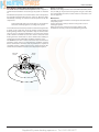
User’Manual
GENUS HE
Condensing wall hung system boiler
G.C.N : 47-116-54 (24 kW)
G.C.N : 47-116-55 (30 kW)
G.C.N : 47-116-56 (38 kW)
GENUS HE 24
GENUS HE 30
GENUS HE 38
The code of practice for the installation,
commissioning & servicing of central heating systems
Supplied By www.heating spares.co Tel. 0161 620 6677
User’s manual
The installation and first ignition of the boiler must be
performed by qualified personnel in compliance with
current national regulations regarding installation, and
in conformity with any requirements established by local
authorities and public health organisations.
After the boiler has been installed, the installer must ensure
that the end user receives the declaration of conformity and
the operating manual, and should provide all necessary
information as to how the boiler and the safety devices
should be handled.
GUARANTEE
The appliance is guaranteed for 24 months from the date of purchase.
Aristons only obligation under the guarantee will be to repair or replace the
faulty appliacnce at Aristons discretion. This will be carried out where the
fault arises from within defects in the appliance, caused either by material or
workmanship of the manufacturer.
This guarantee does not protect malfunction or damage arising from incorrect installation, commissioning or maintenance procedures as laid out in
the installation and servicing manual, inefficient flue system, poor or incorrect electricicty, wrong gas supply or pressure, tampering by inexperienced
persons and any other cause not directly due to manufacture.
MTS (GB) Limited cannot accept responsibility for any cost arising from
repair or maintenance carried out by any third party.
Dear Customer,
Thank you for choosing an ARISTON boiler.
We guarantee that your boiler is a reliable and technically
sound product.
This manual provides detailed instructions and
recommendations for the correct use of the appliance.
Remember to keep this manual in a safe place for future
reference i.e. by the boiler.
Your local MTS Servicing Centre is at your complete disposal
for all requirements.
This appliance is designed to produce central heating and hot
water for domestic use.
It should be connected to a heating system and a distribution
network for domestic hot water, both of which must be
compatible with its performance and power levels.
The use of the appliance for purposes other than those
specified is strictly forbidden. The manufacturer cannot be held
responsible for any damage caused by improper, incorrect and
unreasonable use of the appliance or by the failure to comply
with the instructions given in this manual.
Installation, maintenance and all other interventions must be
carried out in full conformity with the governing legal regulations
and the instructions provided by the manufacturer. Incorrect
installation can harm persons, animals and possessions; the
manufacturing company shall not be held responsible for any
damage caused as a result.
In the event of any maintenance or other structural work in
the immediate vicinity of the ducts or flue gas exhaust devices
and their accessories, switch the appliance off by turning the
electrical switch “OFF” and isolating the gas supply.
Once the work has been completed, ask a qualified technician
to check the efficiency of the flue and the devices.
If the boiler should be out of use for a prolonged period,
it is recommended that the electrical power supply be
disconnected and that the external gas cock be closed. If low
temperatures are expected, the boiler and system pipe work
should be drained in order to prevent frost damage.
Turn the boiler off and turn the external switch “OFF” to clean
the exterior parts of the appliance using a dry cloth.
Do not allow children or inexperienced persons to use the
appliance without supervision.
CE labelling
The CE mark guarantees that the appliance conforms to the following directives:
- 90/396/CEE
relating to gas appliances
- 89/336/CEE
relating to electromagnetic compatibility
- 92/42/CEE
relating to energy efficiency
- 73/23/CEE
relating to electrical safety
Service under the guarantee does not affect the expiry date of the guarantee. The guarantee on parts and appliances which are exchanged ends
when the guarantee on the original appliance expires.
This guarantee does not affect your statutory rights.
You must have your boiler serviced at the end of the first year to validate
your guarantee for the second year.
Safety regulations
Key to symbols:
Failure to comply with this warning implies the risk of personal
injury, in some circumstances even fatal
Failure to comply with this warning implies the risk of damage,
in some circumstances even serious, to property, plants or
animals.
Do not perform operations which involve opening the appliance.
Electrocution from live components.
Personal injury caused by burns due to overheated components, or
wounds caused by sharp edges or protrusions.
Do not perform operations which involve removing the appliance from its installation space .
Electrocution from live components.
Flooding caused by water leaking from disconnected piping.
Explosions, fires or intoxication caused by gas leaking from disconnected piping.
Do not damage the power supply cable.
Electrocution from live uninsulated wires.
Do not leave anything on top of the appliance.
Personal injury caused by an object falling off the appliance as a result
of vibrations.
Damage to the appliance or items underneath it caused by the object
falling off as a result of vibrations.
Do not climb onto the appliance.
Personal injury caused by the appliance falling.
Damage to the appliance or any objects underneath it caused by the
appliance falling away from its installation space.
Do not climb onto chairs, stools, ladders or unstable supports to
clean the appliance.
Personal injury caused by falling from a height or cuts (step ladders
shutting accidentally).
Do not attempt to clean the appliance without first switching it
off and turning the external switch to the OFF position.
Electrocution from live components.
Do not use insecticides, solvents or aggressive detergents to
clean the appliance.
Damage to plastic and painted parts.
Do not use the appliance for any use other than normal domestic
use.
Damage to the appliance caused by operation overload.
Damage caused to objects treated inappropriately.
Do not allow children or inexperienced individuals to operate the
appliance.
Damage to the appliance caused by improper use.If you detect a
smell of burning or smoke coming from the appliance, disconnect it from the electricity supply, turn off the main gas valve,
open all windows and call for assistance.
Personal injury caused by burns, smoke inhalation, intoxication.
If there is a strong smell of gas, turn off the main gas valve, open
all windows and call for assistance.
Explosions, fires or intoxication.
Supplied By www.heating spares.co Tel. 0161 620 6677
User’s manual
Timer Programming
Auto Function
The AUTO function serves to optimise boiler
performance, while maintaining an optimum radiator
temperature and maximum user comfort. It ensures
the building stays at the ideal temperature, whilst
saving energy.
The principle is that the water temperature at the
boiler outlet is automatically adjusted, depending on
the interior ambient temperature.
The boiler allows the temperature to be scheduled
as required directly from the control panel which
displays the operating periods throughout the day.
Info
Allows all information relating to operation of the
boiler and its services to be accessed.
Control Panel
1
16
2
15
14
ABCDEFGHIL123456
13
12
4
11
5
10
6
9
7
8
Legend :
1. Display
2. Reset button
4. Pressure gauge
5. Heating temperature regulation knob/ “encoder”
programming knob
6. Mode button
11. Time clock (optional)
12. ON/OFF button
13. Led burner ON
14. Info button
15. Clock button
16. Auto button (To active Thermoregulation)
(Operation mode selection (summer/winter)
7. Menu/Ok button (Programming key)
8. Esc button
9. Comfort button
10. Domestic Hot Water adjustment knob
Supplied By www.heating spares.co Tel. 0161 620 6677
User’s manual
Display
17
19
18
ABCDEFGHIL123456
17 . Weekly programming
Schedule programming
Day of the week (Mon......Sun)
Zone indication relating to the
display/setting process of the Heating schedule programming (zone
1 and zone 2)
Date and time
Heating schedule programming
activated
18 . Operation and diagnostics
Digits indicating:
boiler status and temperatures
recorded
menu settings
error code signals
Internal temperature displayed
(with bus device optional)
External temperature displayed
(with external sensor optional)
Initial operating and filling procedures.
Check the water pressure on the display regularly and make sure
that the figure is between 0.6 and1.5 bar when the system is cold.
If the pressure is just under the minimum value the display will
request a the boiler be refilled.
To re-pressurise the boiler, it will be necessary to connect
the silver flexible hose supplied to the two isolating points
underneath the boiler, once the hose is connected, open up both
of the black quarter turn handles, once the pressure reads 1.5 bar
on the display, close both handles and disconnect the hose .
If the pressure drops very frequently, there may be a water leak
at some point in the system. If this is the case please contact your
installer and ask them to check it.
Ignition procedure
Press the ON/OFF button on the control panel to switch on the boiler.
The display shows:
Reset button request
Technical assistance request
Digital pressure gauge
Flame detected with indication of
power used or indication of operation shutdown
Heating operation and indication
of the set temperature level
Hot water operation and indication
of the set
temperature level
Scrolling text displaying operation
ABCDE...
as information
Hot Water Comfort activated
19 . Room control and management of peripherals
AUTO function activated
(Temperature regulation
activated) with indication of any
internal (BUS) or external sensors
connected.
Display Info menu
Clip-in solar connected (optional)
Summer
The operating mode will be indicated by the three figures marked
out on the diagram above.
The first figure indicates the operating mode:
0 XX - Stand-by, the text on the display show the
operating mode selected (winter or summer)
C XX- Central heating request
c XX- Heating post-circulation
d XX- Domestic hot water request
H XX - Hot water post-circulation
F XX - Circulation pump anti-freeze protection enabled
- burner anti-freeze protection enabled
The second and third figures indicate:
- the flow temperature when no heating requests have been made
- the flow temperature in central heating mode
- the temperature of the hot water in domestic hot water mode
- the flow temperature in anti-freeze mode.
Supplied By www.heating spares.co Tel. 0161 620 6677
User’s manual
Operating mode selection
Use the MODE button 6 to select the desired operating mode.
Operating mode
Display
heating and hot water production for domestic
use - winter
Switching off the heating
To switch off the heating, press the MODE button; the heating operation symbol will disappear from the display. The Mode button
can be used to keep the domestic hot water production process
active or to place it in standby (modes deactivated).
In the figure below the boiler remains active only for the production of domestic hot water, indicating the set temperature.
hot water production for domestic use only summer
Estate
When the boiler is in stand-by (no request from CH or DHW) the
text on the display indicates the operating mode selected (winter
or summer)
The ignition of the burner is indicated on the display by the symbol the dashes underneath indicate the power output.
Adjusting the heating
Use the MODE button to select the heating and hot water operating
mode. It is possible to set the temperature of the heating water by
adjusting the knob 5. By placing the indicator somewhere between
min. and max. a temperature may be obtained which varies from
about 20°C to about 45°C (low temperature) and about 35°C to
about 82°C (high temperature).
Summer
Switching off the boiler
To switch off the boiler press the ON/OFF button
Stand by
C.Heating Active
The value set previously will flash on the display.
Domestic hot water temperature adjustment
Use the MODE button to select the hot water operating mode.
It is possible to set the temperature of the domestic hot water
by adjusting the knob 10. By placing the indicator somewhere
between min. and max., a temperature may be obtained which
varies from about 36°C to about 60°C.
Switch off the boiler completely by switching the external electrical switch to the OFF position; the display will switch off.
D.H.W. Active
The value set previously will flash on the display.
COMFORT function
To activate the comfort mode it is necessary to press the comfort
button, this will be indicated by a yellow light. The comfort mode
has priority over any other heating request.
There are two settings for the comfort mode (they can be adjusted
in the parameters menu):
1. As soon as DHW is drawn, the secondary heat exchanger is kept
warm for 30 mins.
2. As soon as DHW is drawn, the secondary heat exchanger is kept
warm permanently.
This function may be enabled by pressing the COMFORT button.
When the function is enabled the text COMFORT appears on the
Comfort Cycle in Progress
Supplied By www.heating spares.co Tel. 0161 620 6677
User’s manual
Appliance shut-off conditions
The boiler is protected from malfunctions by means of internal
checks performed by the electronic P.C.B., which stops the boiler
from operating if necessary. In the event of the boiler being shut
off in this manner, a code appears on the control panel display
which refers to the type of shut-off and the reason behind it.
Two types of shut-off may occur:
Safety shut-off
This type of error is “volatile”, which means that the boiler starts
up again automatically as soon as the problem which caused the
shut-off is removed; Err and the error code (e.g. Err/111) ) flash
on the display and the
symbol appears.
In fact, as soon as the cause of the shut-off disappears, the boiler
starts up again and continues to operate normally.
While the boiler is shut off for safety reasons, it is possible to
attempt to restore normal operation by switching the appliance
off and on again using the ON/OFF button on the control panel.
If the boiler still indicates a safety shut-off, switch it off. Make sure
the external electric switch is in the OFF position, and contact a
qualified technician.
Safety shut-off due to insufficient water pressure
If the water pressure inside the heating circuit is insufficient, the
boiler will perform a safety shut-off.
Code 111 (e.g. Err/111) will appear on the display.
To re-pressurise the boiler, it will be necessary to connect
the silver flexible hose supplied to the two isolating points
underneath the boiler, once the hose is connected, open up both
of the black quarter turn handles, once the pressure reads 1.5 bar
on the display, close both handles and disconnect the hose .
If the pressure drops very frequently, there may be a water leak
at some point in the system. If this is the case please contact your
installer and ask them to check it.
Operation shutdown
This type of error is “non-volatile”, which means that it is not
removed automatically. The display will flash Err and the error
code, and
appears with the symbol .
In this case the boiler does not restart automatically, but it may
be reset by pressing the
button. If the problem manifests
itself again after several attempts to reset the appliance, contact a
qualified technician.
IMPORTANT
IF THIS SHUTDOWN OCCURS FREQUENTLY, CONTACT AN
AUTHORISED SERVICE CENTRE FOR ASSISTANCE. FOR SAFETY
REASONS, THE BOILER WILL ALLOW A MAXIMUM OF 5 RESET
OPERATIONS TO TAKE PLACE IN 15 MINUTES (INDIVIDUAL
PRESSES OF THE
BUTTON).
IF THE SHUTDOWN IS OCCASIONAL OR AN ISOLATED EVENT,
THIS IS NOT
NECESSARILY A PROBLEM.
Operation shutdown error table
Display
1 01
5 01
1 03
1 04
1 05
1 06
1 07
1 11
3 05
3 06
3 07
Description
Overheating
No flame detection
Insufficient circulation
Insufficient water pressure
P.C.B. error
P.C.B. error
P.C.B. error
Anti-frost Device.
The anti-frost function acts on the central heating flow temperature probe,
independently from other settings, when the electrical supply is turned
on.
If the primary circuit temperature falls below 8°C the pump will run for 2
minutes.
After the two minutes of circulation (fixed) the boiler will check the following:
a) if the central heating flow temperature is > 8°C, the pump stops;
b) if the central heating flow temperature is between 4 and 8°C, the pump
will run for another two minutes;
c) if the central heating flow temperature is < 4°C, the burner will fire
(heating position) at minimum power until the temperature reaches
33°C, the burner will go off and the pump will continue to run for two
minutes.
The anti-frost device activates only when (with the boiler operating correctly):
- the system pressure is correct;
- the boiler is electrically powered, the symbol is illuminated;
- there is a supply of gas.
No flame detected
Supplied By www.heating spares.co Tel. 0161 620 6677
User’s manual
sub-menu
The parameters relating to each individual menu are listed in the
following pages.
The various parameters can be accessed and modified using the
Menu/Ok button, Mode button and the encoder (see fig. below).
The description of the menus and of each individual parameter will
be shown on the display.
Menu 0
menu
Accessing the settings and adjustment menus
The Menu/Ok button can be used to access a series of menus which
enable boiler operation to be adapted to the system and to the
demands of the user.
The available menus are as follows:
menu 0 = Time-Date-Language
menu 1 = Set Timers
menu 4 = Zone1 Parameters (submenu 0 - parameter 0 1 2)
menu 5 = Zone 2 Parameters (submenu 0 - parameter 0 1 2)
menu Info - accessible with Info button
0
Time-Date-Language
0
0
Setting Display Language
0
1
Setting Time - Date
“Set Time + Date”
description
“Display text”
Clock
button
0
bar
Summer
2
english
italiano
francais
...........
“Language”
Hour
“Set hour and press
MODE”
minutes
“Set minute and press
MODE”
year
“Set year and press
MODE”
month
“Set month and press
MODE”
day
“Set day and press MODE”
day of the
week
(mon.... sun)
“Set Week Day and
press OK”
British Summer Time
Mode
button
Encoder
Menu/Ok
button
(C.H. Temp.
adjusting knob)
Enables the set
values to be
increased or
decreased
Display Informations
digits
menu
setting
Abcdefghijklmno
menu paramètre
Scrolling text
valeur paramètre
Commentaire sur Afficheur
Manual
Automatic
Set Language display
The language is set from menu 0 – sub-menu 0, proceed as
follows:
- press the Menu/Ok button, the display will flash000;
- press the Menu/Ok button, the display will flash 000 ;
- press the Menu/Ok button to access the sub-menu ;
- turn the CH knob, the display will give a list of available languages.
Once the language has been selected, press the MENU/OK button to store the setting,
- press the Esc button to exit the menu.
Setting the time and date
The time and date is set from menu 0 - sub-menu 1, proceed as
follows:
- press the Menu/Ok button, the display will flash000;
- press the Menu/Ok button, the display will flash 000 ;
- turn the CH knob to select the sub-menu 010
- press the Menu/Ok button, to access the sub-menu ;
- the hours, minutes etc. begin to flash in sequence (see table
above).
- Turn the encoder
to select the value and press the MODE
button to confirm each value entered.
- after the last requested value has been entered (the day of the
week), press the MENU/OK button to store the information entered,
- press the ESC button to exit the menu.
British summer time
This is set from menu 0 – sub-menu 0; proceed as follows:
- press the MENU/OK button; 000 will flash on the display.
- press the MENU/OK button again; 000 will flash on the display.
- turn the CH knob to select sub-menu 020.
- press the MENU/OK button again to access the sub-menu.
- press the MENU/OK button to enable the auto update function.
- press the ESC button to exit the menu.
Supplied By www.heating spares.co Tel. 0161 620 6677
User’s manual
MENU 1
SET TIMERS
The boiler can be set to follow a weekly programme which ensures
the operation of the appliance fits your requirements and your
lifestyle.
To access menu 1 proceed as follows:
- press the Menu/Ok button, the display will flash 000,
- turn the CH knob to select menu 100,
- press the Menu/Ok button, to access to menu 1
- Turn the CH knob to scroll through the parameters which may be
set through menu 1; the various parameters are indicated by the text
shown on the display (see table below).
- press the Menu/Ok button to access the parameter.
Pre-set programme 1
from monday to sunday
sub-menu
from 22.00 to 23.59
01 Party Function
from 15 minuties to 6 hours
1
02 Temporary deactivate of Central Heating
“Reduced Temperature”
from 15 minuties to 6 hours
1
03
Funzione Holiday
“Holiday Period”
from 0 day
to 3 month
from 06.00 to 08.00
from 08.00 to 11.30
FF
05 Selection of the zone to be programming
Heating Zone 1
Heating Zone 2
from 11.30 to 13.00
1
06 Pre-set Timer
Pre-set Timer 1
Pre-set Timer 2
Pre-set Timer 3
from 13.00 to 17.00
1
07 Personal or pre-set programming every day of the week
1
08 Personal or pre-set programming for working days
1
10 Personal or pre-set programming
1
11 Personal or pre-set programming
1
12 Personal or pre-set programming
1
13 Personal or pre-set programming
1
14 Personal or pre-set programming
1
15 Personal or pre-set programming
1
16 Personal or pre-set programming
1
17 Copy programming from day to day
“Saturday->Sunday”
ON Period
OFF Period
ON Period
TIME BAND V
OFF Period
TIME BAND VI
from 17.00 to 22.00
ON Period
TIME BAND VII
OFF Period
Pre-set programme 3
from Monday to Sunday
Period
OFF
Period
ON
Period OFF
“Tuesday”
“Thursday”
“Friday”
“Saturday”
“Copy day to day”
TIME BAND I
from 00.00 to 06.00
OFF Period
TIME BAND II
from 06.00 to 08.00
ON Period
TIME BAND III
from 08.00 to 16.00
“Sunday”
Period
OFF
TIME BAND IV
“Monday”
“Wednesday
Period ON
OFF Period
from 22.00 to 23.59
09 Personal or pre-set programming for non-working days
Period Period
ON Period OFF
OFF
TIME BAND III
1
1
Period
ON
TIME BAND II
Heating Zone 1
Heating Zone 2
No Zone
“Monday -> Friday”
Period O
from 00.00 to 06.00
04 Set timer to display
“Monday->Sunday”
OFF Period
TIME BAND I
1
“Pre-set Timers”
ON Period
TIME BAND III
1
“Select Zone To Program”
OFF Period
from 05.30 to 22.00
Set Timers
“Display Zone Timer function”
Period
OFF
TIME BAND II
1
“Party period”
Period ON
OFF
from 00.00 to 05.30
Pre-set programme 2
from Monday to Sunday
description
““Display text””
Period
TIME BAND I
menu
For information relating to changing or scheduling the parameters,
please read the contents of the following pages.
WEEKLY PROGRAMMING
The boiler is supplied with three default operating
programmes
(menu 1 - parameter“pre-set timer” 1 06).
OFF Period
TIME BAND IV
from 16.00 to 22.00
ON Period
TIME BAND V
from 22.00 to 23.59
OFF Period
Supplied By www.heating spares.co Tel. 0161 620 6677
Period ON
Period
OFF
User’s manual
Enabling one of the pre-set programmes
To activate one of the pre-set weekly programmes, proceed as
follows:
- press the Menu/Ok button, on the display flash 000
to select menu100
- turn the CH knob
- press the Menu/Ok button to access the parameters
- turn the CH knob in a clockwise direction until 105 appears
on the display
- press the Menu/Ok button to access heating zone selection
and select “Heating Zone 1”or “Heating Zone 2”
- turn the CH knob
(if present)
- press the Menu/Ok button to confirm the selected zone
- turn the CH knob
to select 106 “Pre-set Timers”
- press the Menu/Ok button to access the pre-set programme
- turn the CH knob to select one of the 3 available programmes
(e.g. “Pre-set Timer 2”) see page 8 for pre-set information
- press the Menu/Ok button to confirm the selection.
- press the Esc button to restore the normal display screen.
Displaying the selected pre-set programme
To display the selected programme, access menu 1 again as
until 104 “Display Zone
indicated above and turn the CH knob
Timer function” appears.
Press Menu/ok button to access the selection of timers to be
displayed. Turn the CH knob
to select the relevant heating zone
(e.g. “Heating Zone 1”).
Press the Menu/ok button again to confirm the selection; the
programme will be shown on the display.
To activate the programmedschedule, after exiting the menu, press the
CLOCK button; the symbol will appear on the display.
bar
bar
Sanitario
bar
Periodo
OFF
OFF period
Besides the modification of the time band shown on the display,
the clock indicates the selected time in steps of 15 minutes.
Once the modification of the pre-set period is complete, press
the Clock button
and select “On period” to programme another
operating stage, in our example this is a single period between
bar
ON period
Periodi
ON
07.00 and 22.00.
Turn the CH knob to move the cursor to the relevant time (22.00
in our example). The cursor, when moved, will make the entire ON
bar
Inverno
Winter
Periodi
ON
ON period
Changing the pre-set programme
In order to adapt the schedule programming to your own
requirements, the pre-set programme may be modified.
Access menu 1 as described on the previous page, then turn the
CH knob until the day(s) for which you wish to modify the pre-set
programme is (are) displayed.
E.g. 109 “Saturday -> Sunday” can be modified as shown below.
TIME BAND I
between 00.00 and 07.00
Press the Clock button
until the text “OFF
Period” appears.
To programme a further inactive heating
period (e.g. “OFF Period” to remove an hour from
the ON period between 06.00 and 07.00).
Turn the CH knob
to move the cursor to
the relevant schedule.
OFF Period
period visible.
After performing all the modifications press the Menu/Ok button to
confirm the schedule programming modification.
Then press the Esc button to restore the normal display screen.
To activate the programmed schedule, after exiting the menu, press
the Clock button ; the symbol will appear on the display.
If “OFF period” or “ON period” is selected, other periods may be entered
so that the programme is adapted to suit your own requirements,
even on a daily basis.
Daily programming may be modified by selecting the relevant day
(within menu 1) and entering new OFF periods and ON periods as
TIME BAND II
between 07.00 and 22.00
ON Period
TIME BAND III
between 22.00 and 23.59
OFF Period
Press Menu/ok to enter modification mode.
The text “Move Cursor” appears on the display; use the CH knob to position
the cursor over the period of time to be modified.
The cursor flashes and the selected time is indicated on the clock
(in steps of 15 minutes).
bar
Muovi
Cursore
Move Cursor
Supplied By www.heating spares.co Tel. 0161 620 6677
User’s manual
Applying a modification to other days of the week
If you wish to modify the programming for a particular day of the
week (e.g. Friday) using the same data entered for another day (or
several other days, for example Saturday -> Sunday, see above), simply copy
the programming from the previously selected day to the next
relevant day.
Access menu 1 as instructed in the previous paragraph and turn
the CH knob until the display shows 117 “copy day to day”.
bar
Copia
giorno
suday
giorno
Copy
day to
Party function
The Party function allows you to set heating operation on (Comfort programme) for a minimum period of 15 minutes and a maximum period
of 6 hours, temporarily cancelling the set daily programming schedule
(see paragraph entitled SCHEDULE PROGRAMMING).
To activate the function, proceed as follows:
- press the Menu/ok button, the display will flash 000
- turn the CH knob to select the menu100 - “Set Timers”
- press the Menu/Ok button to access the parameters
- turn the CH knob until 101 “Party period” appear on the display,
- press the Menu/ok button,
- turn the CH knob to select the desired time period, the schedule
will be shown on the display by the clock
- press the Menu/Ok button to confirm and activate the function.
- the indication “Party Active Until #” will appear on the display.
- press the Esc button to restore the normal display screen.
Press the Menu/ok button to activate the modification; “Select day to
copy from” appears on the display.
Turn the CH knob until you reach the day to copy (e.g. “Saturday”);
the schedule programmed for that day is displayed
bar
Periodo
Party
Party Period
bar
Sabato
Saturday
Press the MENU/OK button; “Select day to copy to” appears on the
display.
bar
Selezionare
giorno
cui copiare
Select day
to su
copy
to
Turn the CH knob until the selected day appears on the display,
e.g. “Friday”.
REDUCED TEMPERATURE function
This function allows you to exclude heating operation (Comfort programme) briefly, for a minimum period of 15 minutes and a maximum
period of 6 hours, temporarily cancelling the set daily programming
schedule (see paragraph entitled SCHEDULE PROGRAMMING).
To activate the function, proceed as follows:
- press the Menu/ok button, the display will flash 000
- turn the CH knob
to select the menu100 - “Set Timers”
- press the Menu/Ok button to access the parameters
until 102 “Reduced Temperature” appears on the
- turn the CH knob
display,
- press the Menu/ok button,
to select the desired time period, the schedule
- turn the CH knob
will be shown on the display by the clock
- press the Menu/Ok button to confirm and activate the function.
- the indication “Reduced Temp Until #” will appear on the display.
- press the Esc button to restore the normal display screen.
bar
TempTemperature
Ridotta
Reduced
bar
Venerdi
Friday
Press the Menu/ok button to confirm the modification.
Press Esc until the normal display screen is restored.
HOLIDAY Function
This function enables the user to suspend boiler operation for a minimum period of 1 day and a maximum period of 3 months.
The normal weekly programme is automatically reactivated at the end
of this set period.
The Holiday function also excludes storage tank heaters.
To activate the function, proceed as follows:
- press the Menu/ok button, on the display flash 000
- turn the CH knob to select the menu100 - “Set Timers”
- press the Menu/Ok button to access the parameters
- turn the CH knob
until 103 “Holiday Period” appears on the
display,
- press the Menu/ok button,
- turn the CH knob
to select the desired time period, the schedule
will be shown on the display by the clock
- press the Menu/Ok button to confirm and activate the function.
- the indication “Holiday Active Until #” will appear on the display.
- press the Esc button to restore the normal display screen.
bar
Funzione
Holiday
Holiday
Period
10
Supplied By www.heating spares.co Tel. 0161 620 6677
User’s manual
sub-menu
4
Zone1 Parameters
4
0
Setpoints
4
0
0
description
“Display text”
range
Setting day
temperature
Zone 1
“Zone1 T Day”
from 10 to 30
(°C )
factoty
setting
menu
parameter
MENU 4 - MENU 5
PARAMETERS HEATING ZONA 1 & 2
19
4
0
1
Setting night
temperature
Zone 1
“Zone1 T Night”
from 10 to 30
(°C )
16
4
0
2
Setting fixed temperature Central
Heating
“FIX Temp.”
from 20 to 82
(°C)
70
5
Zone2 Parameters
5
0
Setpoints
5
0
0
5
5
0
0
1
2
Setting day
temperature
Zone 2
“Zone2 T Day”
from 10 to 30
(°C )
Setting night
temperature
Zona 2
“Zone2 T Night”
from 10 to 30
(°C )
Setting fixed temperature Central
Heating
“FIX Temp.”
from 20 to 82
(°C)
19
16
70
Note
only active
when the
BUS device is
connected
only active with
thermoregulation set
at fixed temperature
only active
when the
BUS device is
connected
only active with
thermoregulation set
at fixed temperature
Setting day and night temperatures for heating zone
If the boiler Genus is connected to a bus device (e.g. remote control
CLIMA MANAGER), the desired ambient temperature can be set for
day and night according to the schedule programme entered.
In central heating mode, the ignition and operation of the boiler
are used to reach and maintain set temperatures.
Setting day temperature
“Zone1 T Day”
To set day temperature , proceed as follows:
- press the Menu/ok button, the display will flash 000
- turn the CH knob
to select the menu400 - “Zone1
Parameters”
- press the Menu/Ok button to access the sub-menu, the display
will flash 00 - “Setpoints”
- press the Menu/Ok button to access the parameters, the display
will flash 400 - “Zone1 T Day”
- press the Menu/ok button to modify the parameter;
- turn the CH knob to select the new temperature;
- press the Menu/Ok button to confirm
- press the Esc button to restore the normal display screen.
To set the day temperature - heating zone 2 (if present) proceed as
Heating Zone 1 selecting menu 5.
bar
Zona
1TGiorno
Zone1
T Day
Setting night temperature
“Zone1 T Night”
To set the night temperature , proceed as follows:
- press the Menu/ok button, the display will flash 000
- turn the CH knob
to select the menu400 - “Zone1
Parameters”
- press the Menu/Ok button to access the sub-menu, the display
will flash 00 - “Setpoints”
- press the Menu/Ok button to access the parameters, the display
will flash 400
- turn the encoder
to select the parameter 401
- “Zone1 T Night”
- press the Menu/ok button to modify the parameter;
- turn the CH knob
to select the new temperature;
- press the Menu/Ok button to confirm
- press the Esc button to restore the normal display screen.
To set the night temperature - heating zone 2 (if present) proceed
as Heating Zone 1, selecting menu 5.
bar
Zona 1TNotte
Zone1
T Night
11
Supplied By www.heating spares.co Tel. 0161 620 6677
User’s manual
Set fixed flow temperature on the heating zone
The parameter is used to modify the heating flow temperature if the
temperature regulation at a fixed value is activated.
The temperature of Zone 1 and Zone 2 (if present) may be adjusted.
To modify the temperature set, proceed as follow:
- press the Menu/ok button, the display will flash 000
- turn the CH knob
to select the menu400 - “Zone1
Parameters”
- press the Menu/Ok button to access the sub-menu, the display
will flash 00 - “Set points”
- press the Menu/Ok button to access the parameters, the display
will flash 400
- turn the CH knob to select the parameter 402
- “FIX Temp”
- turn the CH knob to select the new temperature;
- press the Menu/Ok button to confirm
- press the Esc button to restore the normal display screen.
To set the Fixed temperature - heating zone 2 (if present) proceed
as Heating Zone 1, selecting menu 5.
INFO ( ) - display only
- accessed by pressing the button
Inverno
If the Info button is pressed, a menu is accessed which enables the
data listed in the table below to be displayed.
The display scrolls through various information when the CH knob
is turned.
Press the Esc button to restore the normal display screen.
Informations displayed
Time of day - Hour
Heating circuit pressure (bar)
External temperature (°C)
-only with external sensor connected
Room temperature (°C)
- only active when the BUS device is connected
D.H.W. Flow rate (l/m)
Set C.H. temperature (°C)
Set D.H.W. temperature (°C)
Month until next maintenance
Technical Assistance Centre telephone number and name
(only display if setted parameters 890 - 891)
D.H.W. comfort temperature (°C) - if activated
AUTO Function
“enabled” or “disabled”
12
Supplied By www.heating spares.co Tel. 0161 620 6677
User’s manual
Auto button - Temperature adjustment activation
The AUTO function enables boiler operation to be adapted to
environmental conditions and to the type of system it is installed
on.
Comfortable temperature is reached inside the room in the quickest
way possible, without wasting money, energy or efficiency, while
substantially reducing the amount of wear experienced by the
components.
Your installer will advise you on the devices connectable to
the boiler and will program it according to the system.
In normal boilers the water temperature inside the heating elements
is usually set to a high value (70-80°C), thereby ensuring effective
heating during the few really cold winter days. It then becomes
excessive on less cold days (of which there are many) more typical
of the autumn and winter seasons. This leads to excessive room
heating after the thermostat has been switched off, resulting in
energy waste and uncomfortable conditions inside the room.
The AUTO function “takes control” of the boiler and selects the best
operating regime based on environmental conditions, external
devices connected to the boiler and the performance required. It
constantly decides at which power level to operate based on the
environmental conditions and the room temperature required.
External
sensor
Change of gas type
Our boilers are designed to function either with Natural Gas (methane) or L.P.G. gas. If you need to change from one gas to the other,
one of our Authorised Service Centres must be contacted to convert the appliance.
Maintenance
Schedule an annual maintenance check-up for the boiler with a
competent person.
Correct maintenance always results in savings in the cost of
running the system.
Failure to arrange an annual service for the appliance will
invalidate the second year of the manufacturers guarantee.
Room
sensor
C.Heating
13
Supplied By www.heating spares.co Tel. 0161 620 6677
User’s manual
14
Supplied By www.heating spares.co Tel. 0161 620 6677
User’s manual
15
Supplied By www.heating spares.co Tel. 0161 620 6677
MTS (GB) Limited
MTS Building
Hughenden Avenue
High Wycombe
Bucks HP13 5FT
Telephone: (01494) 755600 Fax: (01494) 459775
Internet: www.mtsgroup.com/uk
E-mail: [email protected]
Technical Advice: 0870 241 8180
Customer Service: 0870 600 9888
Professional Team Limited
Suites 9 & 10, Plaza 256
Blanchardstown Corporate Park 2
Ballycoolin
Dublin 15
Telephone: (01) 810 3723
Fax: (01) 810 3727
Internet: www.mtsgroup.com/ie
E-mail: [email protected]
Technical Advice: (01) 437 0121
Customer Service: (01) 437 0121
Supplied By www.heating spares.co Tel. 0161 620 6677
420010096201 - 08/2007
Commercial subsidiaries: