1
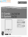
E-Combi 24/30/38
E-System 24/30
CONDENSING WALL HUNG
COMBINATION BOILER
G.C.N : 47 - 116 - 62 (24 kW)
G.C.N : 47 - 116 - 63 (30 kW)
G.C.N : 47 - 116 - 64 (38 kW)
CONDENSING WALL HUNG
O.H. BOILER
G.C.N : 41 - 116 - 34 (24 kW)
G.C.N : 41 - 116 - 35 (30 kW)
Country of destination GB, IE
Supplied By www.heating spares.co Tel. 0161 620 6677
User Manual
Dear Customer,
Thank you for choosing an ARISTON boiler.
We guarantee that your boiler is a reliable and technically
sound product. This manual provides detailed instructions and
recommendations for the correct use of the appliance.
Remember to keep this manual in a safe place for future
reference i.e. by the boiler.
Your local ARISTON Servicing Centre is at your complete
disposal for all requirements.
GUARANTEE
The manufacturer’s guarantee is for 2 years from the date of
purchase. The guarantee is invalidated if the appliance is not
installed in accordance with the recommendations made herein
or in a manner not approved by the manufacturer. To assist us in
providing you with an efficient after sales service, please return
the guarantee registration card enclosed with the boiler without
delay.
Ariston only obligation under the guarantee will be to repair
or replace the faulty appliance at Ariston discretion. This will
be carried out where the fault arises from defects within the
appliance, caused either by material or workmanship of the
manufacturer.
This guarantee does not protect malfunction or damage arising
from incorrect installation, commissioning or maintenance
procedures as laid out in the installation and servicing manual,
inefficient flue system, poor or incorrect electricicty, wrong gas
supply or pressure, tampering by inexperienced persons and
any other cause not directly due to manufacture.
ARISTON (GB) Limited cannot accept responsibility for any cost
arising from repair or maintenance carried out by any third
party.
Repair under the guarantee does not affect the expiry date
of the guarantee. The guarantee on parts and appliances
which are exchanged ends when the guarantee on the original
appliance expires.
This guarantee does not affect your statutory rights.
You must have your boiler serviced at the end of the first year
to validate your guarantee for the second year and ensure the
Benchmark serv. internal Record is completed.
The installation and first ignition of the boiler must be performed
by qualified personnel in compliance with current national
regulations regarding installation, and in conformity with any
requirements established by local authorities and public health
organisations.
After the boiler has been installed, the installer must ensure
that the end user receives the declaration of conformity and the
operating manual, and should provide all necessary information
as to how the boiler and the safety devices should be handled.
This appliance is designed to produce central heating and domestic
use only.
It should be connected to a heating system and a distribution network
for domestic hot water, both of which must be compatible with its
performance and power levels.
The use of the appliance for purposes other than those specified is
strictly forbidden. The manufacturer cannot be held responsible for
any damage caused by improper, incorrect and unreasonable use of
the appliance or by the failure to comply with the instructions given
in this manual.
Installation, maintenance and all other interventions must be carried
out in full conformity with the governing legal regulations and the
instructions provided by the manufacturer. Incorrect installation can
harm persons, animals and possessions; the manufacturing company
shall not be held responsible for any damage caused as a result.
In the event of any maintenance or other structural work in the
immediate vicinity of the ducts or flue gas exhaust devices and their
accessories, switch the appliance off by switching the external bipolar
switch to the “OFF” position and shutting off the gas valve.
When the work has been completed, ask a qualified technician to
check the efficiency of the ducting and the devices.
If the boiler should be out of use for a prolonged period, it is
recommended that the electrical power supply be disconnected
and that the external gas cock be closed. If low temperatures are
expected, the boiler and system pipe work should be drained in
order to prevent frost damage.
Turn the boiler off and turn the external switch “OFF” to clean the
exterior parts of the appliance.
Do not allow children or inexperienced persons to use the appliance
without supervision.
CE labelling
The CE mark guarantees that the appliance conforms to the following
directives:
- 90/396/CEE
relating to gas appliances
- 2004/108/CEE
relating to electromagnetic compatibility
- 92/42/CEE
relating to energy efficiency
- 2006/95/CEE
relating to electrical safety
2
Supplied By www.heating spares.co Tel. 0161 620 6677
User Manual
The Benchmark Scheme
ARISTON is a licensed member of the Benchmark Scheme which aims
to improve the standards of installation and commissioning of domestic heating and hot water systems in the UK and to encourage regular
servicing to optimise safety, efficiency and performance.
Benchmark is managed and promoted by the Heating and Hotwater Industry Council. For more information visit www.centralheating.
co.uk
Please ensure that the installer has fully completed the Benchmark
Checklist on the inside back pages of the installation instructions supplied with the product and that you have signed it to say that you
have received a full and clear explanation of its operation. The installer
is legally required to complete a commissioning checklist as a means
of complying with the appropriate Building Regulations (England and
Wales).
All installations must be notified to Local Area Building Control either
directly or through a Competent Persons Scheme. A Building Regulations Compliance Certificate will then be issued to the customer who
should, on receipt, write the Notification Number on the Benchmark
Checklist.
This product should be serviced regularly to optimise its safety, efficiency and performance. The service engineer should complete the
relevant Service Record on the Benchmark Checklist after each service.
The Benchmark Checklist may be required in the event of any warranty work and as supporting documentation relating to home improvements in the optional documents section of the Home Information
Pack.
Safety regulations
Key to symbols:
Failure to comply with this warning implies the risk of personal
injury, in some circumstances even fatal
Failure to comply with this warning implies the risk of damage, in
some circumstances even serious, to property, plants or animals.
Do not perform operations which involve opening the appliance.
Electrocution from live components.
Personal injury caused by burns due to overheated components,
or wounds caused by sharp edges or protrusions.
Do not perform operations which involve removing the appliance
from its installation space .
Electrocution from live components.
Flooding caused by water leaking from disconnected piping.
Explosions, fires or intoxication caused by gas leaking from
disconnected piping.
Do not damage the power supply cable.
Electrocution from live uninsulated wires.
Do not leave anything on top of the appliance.
Personal injury caused by an object falling off the appliance as a
result of vibrations.
Damage to the appliance or items underneath it caused by the
object falling off as a result of vibrations.
Do not climb onto the appliance.
Personal injury caused by the appliance falling.
Damage to the appliance or any objects underneath it caused by
the appliance falling away from its installation space.
Do not climb onto chairs, stools, ladders or unstable supports to
clean the appliance.
Personal injury caused by falling from a height or cuts (stepladders
shutting accidentally).
Do not attempt to clean the appliance without first switching it off
and turning the external switch to the OFF position.
Electrocution from live components.
Do not use insecticides, solvents or aggressive detergents to clean
the appliance.
Damage to plastic and painted parts.
Do not use the appliance for any use other than normal domestic
use.
Damage to the appliance caused by operation overload.
Damage caused to objects treated inappropriately.
Do not allow children or inexperienced individuals to operate the
appliance.
Damage to the appliance caused by improper use.
If you detect a smell of burning or smoke coming from the appliance,
disconnect it from the electricity supply, turn off the main gas valve,
open all windows and call for assistance.
Personal injury caused by burns, smoke inhalation, intoxication.
If there is a strong smell of gas, turn off the main gas valve, open all
windows and call for assistance.
Explosions, fires or intoxication.
This appliance is not intended for use by persons (including children)
with reduced physical, sensory or mental capabilities, or lack of
experience and knowledge, unless they have been given supervision or
instruction concerning use of the appliance by a person responsible for
their safety.
Children should be supervised to ensure that they do not play with the
appliance.
3
Supplied By www.heating spares.co Tel. 0161 620 6677
User Manual
Control panel
1
40°
2
50°
60°
70°
80°
10
90°
9
3
8
on/off
7
I
4
O
6
5
E-SYSTEM
1
40°
2
50°
60°
70°
80°
90°
10
9
3
on/off
4
5
Legend :
1.
2.
3.
4.
5.
6.
7.
8.
Green indicator : CH temperature and error indicator
ON/OFF button
Green indicator : ON/OFF
Pressure gauge
Winter / Summer switch - Heating temperature regulation knob
Domestic Hot Water adjustment knob (E-Combi models)
Time clock (E-Combi models)
Green indicator : flame ON
Red indicator : lockout light
9. Yellow indicator : flashing error light
10. RESET button
4
Supplied By www.heating spares.co Tel. 0161 620 6677
8
User Manual
Initial operating procedures
Filling instructions
Check the water pressure on the pressure gauge regularly and make
sure that the figure is between 0.6 and1.5 bar when the system is
cold. If the pressure is just under the minimum value, re-establish the
correct pressure by using the filling loop.
If the pressure drops very frequently, there may be a water leak at
some point in the system. If this is the case a plumber should be
contacted
Ignition procedure
Press the ON/OFF button on the control panel to switch on the boiler.
The green LED 3 will illuminate indicating that the boiler is ready to
operate.
The electronic control unit will ignite the burner, without any manual
intervention but in response to the request for Domestic Hot Water
or Central Heating. If, after approximately 10 seconds, the burner has
not ignited, the boiler’s safety devices will shut off the gas and the red
LED 8 illuminates. To reset the ignition system, the Reset button 10
must be pressed and released.
40°
50°
60°
70°
80°
Adjusting the heating
It is possible to set the temperature of the heating water by adjusting
the knob 5. By positioning the indicator somewhere between
min. and max. A temperature may be obtained which varies from
approximately 40°C to approximately 82°C.
The water temperature in the primary circuit may be checked by
means of the green leds 1.
1
60°
50°
40°
70°
80°
90°
on/off
I
O
5
90°
on/off
I
Domestic Hot Water temperature adjustment - E-COMBI
It is possible to set the temperature of the domestic hot water by
adjusting the knob 6. A temperature may be obtained which varies
from approximately 36°C to approximately 60°C.
O
40°
60°
50°
70°
80°
90°
on/off
I
O
Should the boiler fail to ignite a second time, check that the external
gas cock is open. If the problem persists, contact an Authorised
Service Centre.
40°
50°
60°
70°
80°
6
90°
on/off
I
O
Winter or summer operating modes
In the “winter” operating mode, the boiler will produce both Central
Heating and Domestic Hot Water. In the “summer” operating mode,
the boiler will produce only Domestic Hot Water. Using the knob on
the control panel, the user can select “winter” or “summer” operating
mode. Keeping the knob 5 at the
position selects the “summer”
operating mode. “Winter” operating mode may be selected by
positioning the knob 5 between the min. and max. settings.
Switching off the heating
To switch off the heating mode turn
the button 5 to the position
. The
boiler will now only produce Domestic
Hot Water.
Stand by
To switch off the boiler press the ON/OFF button 2. The green LED 3
will go off.
Switch off the boiler completely by switching the external electrical
switch to the OFF position.
40°
50°
60°
70°
80°
90°
on/off
I
O
5
Supplied By www.heating spares.co Tel. 0161 620 6677
User Manual
Boiler protection devices
Clock Instructions - E-COMBI
3
4
1
24
23
22
A
2
The boiler is protected from malfunctioning by means of internal
checks performed by the electronic microprocessor P.C.B., which
stops the boiler from operating if necessary.
In the event of the boiler being shut off in this manner, the LED shows
the type of shut-off and the reason behind it.
There are two types of shut-off :
12
5
21
Safety shut-off
6
7
19
9
20
I
C
8
18
9
17
B
15
14
13
10
16
6
This type of error is “volatile”, which means that the boiler starts up
again automatically as soon as the problem which caused the shut-off
is removed; the yellow LED 9 flashes and the C.H. temperature LED 1
indicate the error code. (see table)
As soon as the cause of the shut-off disappears, the boiler starts up
again and continues to operate normally.
If the boiler still indicates a safety shut-off , switch it off. Make
sure the external electric switch is in the OFF position and contact
a qualified technician.
12
11
Shutdown due to insufficient water circulation
4. For operation
Put the selector switch B to the
symbol to control the central
heating by the clock. Put the switch B to “I”
If the green leds 1 flash and the boiler is off , one possible cause for this
state is an insufficient pressure of water in the system - green LED 4050 blink. Check the water pressure on the pressure gauge 4 and make
sure that is between
0.6 and 1.5 bar when
the system is cold. If
the pressure is just
under the minimum
refill the system by
opening the valve
under the boiler.
If the pressure drops
very frequently, there
may be a water leak
at some point in the
Note: Connections viewed from behind boiler
system. If this is the
case a plumber should
be contacted.
to select permanent operation or to “0” to turn the central heating off
permanently.
Operation shutdown
1. General layout
The mechanical clock covers a 24 hour period. Each tappet represents 15 minutes A. An override switch is located on the clock B.
2. To set the time
To set the time of day, grasp the outer edge of the dial and turn slowly clockwise until the correct time is lined up with the arrow C.
3. To Set the “On” and “Off ” times
The clock uses a 24hours system. e.g. 8 = 8.00 am and 18 = 6.00 pm
“ON” periods are set by sliding all tappets between the “ON” time and
the “OFF” time to the outer edge of the dial.The tappets remaining at
the centre of the dial are the “OFF” periods.
This type of error is “non-volatile”, which means that it is not removed
automatically (the red LED 8 will illuminate and the C.H. temperature
LED 1 will indicate the error code). In this case the boiler does not
restart automatically, but it may be reset by pressing the
button. If the problem manifests itself again after several attempts to
reset the appliance, contact a qualified technician.
Important
If this shutdown occurs frequently, contact an authorised service
centre for assistance. For safety reasons, the boiler will allow
a maximum of 5 reset operations to take place in 15 minutes
(individual presses of the button). If the shutdown is occasional
or an isolated event, this is not a problem.
6
Supplied By www.heating spares.co Tel. 0161 620 6677
User Manual
Table summarising error codes
40
●
Green Leds
Temperature indicator
50 60 70 80
●
●
●
●
●
●
●
●
●
●
●
●
●
●
●
●
●
●
●
●
●
●
●
●
●
●
●
●
●
●
●
●
●
●
Reset
90
●
yellow
red
●
●
X
X
●
X
●
X
●
X
●
X
●
●
X
X
●
●
●
●
●
●
●
●
●
●
●
●
●
●
●
●
●
●
●
●
●
●
●
●
Description
Note
❍ = flashing light
● = lit
Overheat
Insufficient circulation
Insufficient water (request filling)
C.H. Flow temp. probe circuit open / short circuit
C.H. Return temp. probe circuit open / short circuit
External sensor circuit open / short circuit
Floor thermostat contact open
Heating delivery probe problem
Insufficient circulation
EEPROM error
Communication error
Too many (> 5) resets in 15 minutes
Main P.C.B. error
Room sensor circuit open / short circuit
No flame detected
Flame detected with gas valve closed
Flame lift
1st Ignition Failed
2nd Ignition Failed
Flame cut-off
Thermofuse open
Fan speed error
Anti-frost Device.
Change of gas type
When the electrical supply is turned on, the anti-frost function acts
on the central heating flow temperature probe, independently from
other safety devices.
If the primary circuit temperature is between 3°C and 8°C the
pump will run (with the diverter valve switching between central
heating and hot water every 1 minute) until the temperature
reaches > 9°C.
If the flow temperature remains between 3°C and 8°C the pump will
continue to run for a maximum of 20 minutes unless a temperature
above > 9°C is detected in the central heating flow, after this the
burner will fire (heating position) until a temperature of > 30°C is
detected.
If the central heating flow temperature is < 3°C, the burner will fire
(heating position) at minimum power until the temperature reaches
> 30°C, the burner will go out.
If lockout is caused by overheat the burner will not fire but the pump
will continue to run (heating position).
The anti-frost device activates only when (with the boiler operating
correctly):
- the system pressure is correct;
- the boiler is electrically powered;
- there is a supply of gas.
Our boilers are designed to function either with Natural Gas (methane) or L.P.G. gas. If you need to change from one gas to the other,
one of our Authorised Service Centres must be contacted to convert
the appliance.
Maintenance
Schedule an annual maintenance check-up for the boiler with a competent person.
Correct maintenance generally results in savings in the cost of running the system.
Failure to arrange an annual service for the appliance will invalidate
the second year of the manufacturer’s guarantee.
7
Supplied By www.heating spares.co Tel. 0161 620 6677
Hughenden Avenue
High Wycombe
Bucks HP13 5FT
Telephone: (01494) 755600
Fax: (01494) 459775
Internet: www.aristonthermo.co.uk
Technical Advice: 0870 241 8180
Customer Service: 0870 600 9888
Professional Team Limited
Suites 9 & 10, Plaza 256
Blanchardstown Corporate Park 2
Ballycoolin
Dublin 15
Telephone: (01) 810 3723
Fax: (01) 810 3727
Internet: www.aristonthermo.ie
Technical Advice: (01) 437 0121
Customer Service: (01) 437 0121
Supplied By www.heating spares.co Tel. 0161 620 6677
420010275700
Ariston Thermo UK Ltd